Abstract
A continuum damage mechanics model using FEM calculations was proposed to be applied to an analysis of the fuel failure due to pellet cladding mechanical interaction (PCMI) under reactivity-initiated accident conditions. The model expressed ductile fracture via two processes: damage nucleation related to void nucleation and damage evolution related to void growth and linkage. The boundary conditions for the simulations were input from the fuel performance codes FEMAXI-7 and RANNS. The simulation made reasonable predictions for the cladding hoop strain at failure and reproduced the typical fracture behavior of the fuel cladding under the PCMI loading, characterized by a ductile shear zone in the inner region of the cladding wall. It was shown that occurrence of a through-wall crack is determined at an early stage of crack propagation, and the rest of the through-wall penetration process is achieved with a negligible increment in strain. The effect of a local temperature rise in the cladding inner region on the failure strain was found to be less than 5% for the conditions investigated. Failure strains predicted under a plane strain loading were smaller by 20%–30% than those predicted under equibiaxial tensions between the hoop and the axial directions.
1. Introduction
Failure of high-burnup LWR fuels under reactivity-initiated accident (RIA) conditions is induced mainly by pellet cladding mechanical interaction (PCMI) loading on embrittled cladding [Citation1,2]. In the case of high-burnup PWR fuels, the layer of circumferentially oriented hydride clusters accumulated in the cladding periphery, called “hydride rim”, plays an important role in PCMI failure. It is understood that shallow cracks with similar lengths to the hydride rim thickness are generated at an early stage of the PCMI loading, and when one of these cracks penetrates inward it leads to a through-wall crack [Citation2,3]. However, such anticipated processes cannot be confirmed by direct observation since the failure is quite a rapid phenomenon that occurs inside the cladding wall. For the same reason, it is so far not fully understood how and to what degree the fracture processes are influenced by other known factors specific to the PCMI loading, namely, the biaxial stress state with tensions in the hoop and the axial directions of the cladding and the local temperature rise in the cladding inner region which can result in temperature difference of several hundred degrees centigrade between the cladding inner and outer regions [Citation4].
In order to overcome this difficulty, the present study has adopted a continuum damage mechanics model that has enabled us to computationally simulate the fracture processes of interest, such as crack growth initiation and crack propagation [Citation5]. The damage model was validated based on the mechanical tests conducted previously at the Japan Atomic Energy Agency (JAEA) [Citation6–8] to treat the fracture behavior of cold-worked stress-relieved (CWSR) Zircaloy-4 (Zry-4) cladding. Such an approach is in concert with an effort to determine a local fracture criterion for the cladding material which is applicable to varied loading conditions. A damage analysis with a well-validated model is expected to provide better insight on the detailed PCMI failure behaviors, and the roles of the stress state and the local temperature of the cladding.
The framework of the damage model and the identification of the model parameters are described in Section 2. After calibrating the model parameters, the damage analysis was applied to the RIA-simulated experiments with unirradiated and pre-hydrided claddings conducted in the Nuclear Safety Research Reactor (NSRR) [Citation3]. The cladding stress state and the cladding temperature profile during the transient were input from the experimental analysis using the fuel performance codes FEMAXI-7 and RANNS [Citation4,Citation9]. The application of the damage analysis to the RIA-simulated experiments is described in Section 3, along with a discussion of the effects of the stress state and the local temperature of the cladding. Concluding remarks are provided in Section 4.
2. Simulation models
2.1. Framework of the damage model
2.1.1. FEM calculation
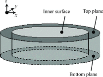
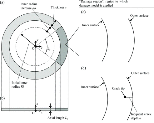
The finite element models for the present damage mechanics calculations were constructed with the Abaqus code (version 6.11) [Citation5]. illustrates an elevation of the cladding-tube model, and designates the parts to which we will refer when explaining the calculation conditions. The z-axis corresponds to the longitudinal direction of the cladding tube.
The following constraints were applied to all the Abaqus calculations presented in this paper. First, any rotation about the x- or y-axis was forbidden at all the nodes in the finite element model. Second, the nodes belonging to the top plane or the bottom plane were constrained to have a unique z-coordinate in each plane. Third, any mesh refinement in the z-direction was forbidden; the model consisted solely of one-element layer in the longitudinal direction. In other words, the present analysis was effectively a two-dimensional analysis in the xy-plane, while a three-dimensional model was used. It was confirmed that the model gave an equivalent result to that derived from a corresponding plane strain analysis with a two-dimensional model when zero displacement was applied to the top and the bottom planes. Employing such a three-dimensional model was necessary for considering stress states which deviate from the plane strain condition.
A geometrically nonlinear analysis was performed with (first-order) linear, reduced integration, and eight-node brick elements [Citation5]. The spatial distribution and time evolution of the cladding temperature were given as prescribed conditions of the calculation; no heat transfer phenomena were included. In the calculations with the damage model, an explicit scheme was adopted for the time integration of constitutive equations because the implicit scheme often exhibited poor convergence characteristics in treating the dynamic fracture processes described by the damage model.
The elastoplastic constitutive response of CWSR Zry-4 cladding was calculated based on an isotropic hardening and an “associated flow” incremental plasticity model [Citation5]. Le Saux constitutive model, a well-calibrated model based on several types of mechanical tests performed on CWSR Zry-4 cladding specimens [Citation10], was adopted for the elasticity, yield surface function, and the evolution law defining plastic hardening, using model parameters ϕt = 0.0 m−2 for neutron fluence, ξ = 0.0 for normalized axial position, and strain rate 0.01 s−1.
2.1.2. Damage description
Fractographic observations performed after the RIA-simulated experiments at the NSRR indicated that local fracture of zirconium-based alloy claddings had occurred mainly in a ductile manner, even in cases where the claddings were macroscopically brittle due to the hydride-induced embrittlement [Citation1,Citation3]. Accordingly, the present damage analysis adopted a phenomenological ductile fracture model provided in Abaqus [Citation5]. In the model, damage is expressed via descriptions of two processes: damage initiation related to void nucleation and damage evolution related to void growth and linkage. The model is thus capable of treating damage initiation, progressive damage evolution, and fracture in the FEM calculations. The material stiffness is degraded progressively after damage initiation, and the complete loss of load-carrying capacity is treated as a local fracture of the material.
The onset of damage due to void nucleation was predicted by the phenomenological model in which the damage initiation criterion was met when the following condition was satisfied:
(1) where
is the equivalent plastic strain,
is the model parameter corresponding to the equivalent plastic strain at the onset of damage, and ωD is a state variable.
Once the initiation criterion was satisfied, the material stiffness was degraded in accordance with the following stress-correction equations:
(2)
(3)
(4) where S and p are the effective deviatoric stress tensors and pressures computed for the degraded elements,
and
are those that would exist in the elements in the absence of damage, and D is the damage variable, which represents the damage evolution as additional nucleation, growth, and coalescence of voids after the damage initiation. An element is considered to have lost its load-carrying capacity and thus was removed from the mesh when the maximum degradation D = 1.0 was reached at any one integration point of the element.
The evolution of the damage variable D was expressed by
(5)
(6) where
is the equivalent plastic displacement after the damage initiation (zero when ωD < 1.0),
is the model parameter corresponding to
at the onset of fracture (D = 1.0), α = 0.1, and L is the characteristic length, defined as a side of an element shape. For example, L = a for an a × a × a cubic element. The formulation of the variable D, based on plastic displacement rather than plastic strain, was adopted to alleviate the strong mesh dependency of the dissipated energy during the damage process [Citation11].
The two unknown parameters, and
, need to be determined using experimental information. The former and the latter correspond to the criteria for damage initiation and final fracture, respectively, of a finite element.
2.2. Identification of model parameters using mechanical test data
Identification of the damage model parameters, and
, was performed by using experimental data taken primarily from tube-burst and expansion-due-to-compression (EDC) tests previously conducted at JAEA. Detailed descriptions of the relevant mechanical tests are given in [Citation6,7]. It was assumed that the model parameters would not depend on the stress state. The validity of this assumption is discussed in Section 2.2.4. The dependencies of the model parameters on the strain rate were not considered since it was reported that the influence of the strain rate on the failure behavior was small [Citation6].
shows the best-fit set of the damage model parameters that were determined in the present study. In the damage analysis, each of the parameters and
was treated as a linear function of the temperature as defined by the values for that parameter at 300 and 620 K. They were tuned so that the analysis reproduced the measured failure strains of the cladding specimens obtained in the mechanical tests. One should note that the parameters at 620 K are results from tentative fitting, since there was less test data available compared to that at 300 K, and thus, the uncertainty in the utilized data at 620 K is large, as described in Section 2.2.3.
Table 1. Damage model parameters.
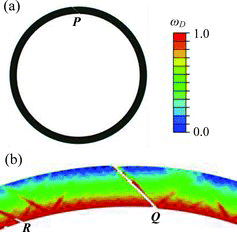
(a) and (b) illustrate the horizontal and vertical cross sections of the cladding model, respectively. The angle θd defines the “damage region” to which the aforementioned damage model was applied. In the present analysis, failure of the cladding was defined as the generation of a through-wall crack at any position in the damage region. The damage region consisted of homogeneous elements with almost cubic shapes and a characteristic length L. The axial length LZ was set to be equal to L so that the elements in the damage region had aspect ratios close to unity; generally, elements with large aspect ratios should not be used because they will have different behaviors depending on the orientations of cracks [Citation5].
Figure 2. FEM models of the cladding tube: (a) horizontal cross section, (b) vertical cross section, (c) geometry of the damage region for smooth specimens, and (d) geometry of the damage region for pre-cracked specimens.
2.2.1. Burst test at room temperature with nonhydrided specimens
Nagase et al. performed a closed-end tube-burst test with unirradiated CWSR Zry-4 specimens at room temperature [Citation6]. For each failed sample, the residual hoop strain was estimated through photoimage analysis of the horizontal cross-section at the axial position where the maximum radial expansion had occurred. The estimated residual hoop strains of the nonhydrided samples were about 7.5% on average.
The specimen was modeled as a smooth ring as shown in (c), with an inner radius of 4.18 mm and an outer radius of 4.75 mm. The entire body was treated as a damage region, i.e. θd = 2π, to avoid introducing an artificial inhomogeneity at the boundary between the damage region and the nondamage region. The mesh size was 20 μm, which was fine enough for the test with the smooth specimen; further refining of the mesh did not affect the calculation results of interest, such as failure strain and fracture appearance.
A load-controlled analysis was performed. Spatially homogeneous pressure, increasing linearly with time, was applied to the inner surface of the cladding tube. That is, the inner radius increase dR (see (a)) was introduced via the applied pressure. Displacements of the top and bottom planes (see ) in the axial direction were enforced to be zero to simulate plane strain loading. The calculated residual hoop strain was defined as (ϵpli, avg + ϵo, avgpl)/2, where ϵpli, avg and ϵplo, avg are the plastic hoop strains averaged circumferentially along the inner surface and the outer surface, respectively, at the instant of failure.
The analysis conducted at 300 K with the best-fit parameters gave a residual strain of 7.6% after the burst failure. In addition, the analysis showed a fracture appearance similar to that observed in the burst test, characterized by ductile shear across the wall thickness. (b) shows the magnified image of the simulated fracture appearance around the fracture position P in (a). The damage initiation criterion (ωD = 1.0) was reached first at the inner surface of the cladding. Element deletion occurred at several circumferential positions, as seen at the positions Q and R, and one of them penetrated the cladding wall into the outer surface as seen at the position Q.
2.2.2. RAG–EDC test
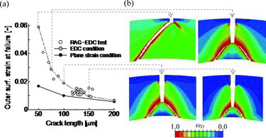
Fukuda et al. performed the EDC test with unirradiated CWSR Zry-4 specimens at room temperature [Citation8]. The specimens were cladding tubes with an artificial crack in the peripheral region, which had been introduced into the tubes using the “rolling-after-grooving (RAG)” process developed by JAEA [Citation8]. The diameter change of the specimens was monitored and recorded with laser displacement sensors. The failure of the specimens was detected as a sudden drop of the load of the plunger compressing the Teflon pellet. The outer-surface strain of the specimen at failure decreased from about 4% to 1% as the artificial crack length increased from about 60 to 160 μm.
The specimen was modeled as a ring with an inner radius of 4.11 mm and an outer radius of 4.75 mm. A crack was introduced as shown in (d). The damage region was set with θd = π/20 since it was previously known that a failure would occur around the crack.
Results from the continuum damage mechanics model on cracked structures are inevitably mesh size dependent [Citation12]. To cope with this problem, the mesh size around a crack tip was treated as a model parameter; a consistent mesh size of L = 10 μm in the damage region was used in all the calculations on the cracked structures. The value L = 10 μm was about the lower limit of the mesh size with which a damage analysis could be performed with an acceptable computational cost.
A load-controlled analysis was performed. The boundary conditions of the burst test and the EDC test analyses were the same except that the top plane was allowed to move freely in the axial direction in the latter case. Such an unconstrained condition was suitable for simulating the EDC test, where the loading condition was close to uniaxial tension in the hoop direction [Citation13].
shows an excellent agreement between the measurements and the calculations (labeled “EDC condition”) of the outer surface strains at failure. As shown in the figure, the simulated fracture appearances of the specimens with 75-, 100-, and 150-μm cracks are similar to those observed in the test [Citation7], characterized by the straight crack propagation along the crack plane, followed by ductile shear near the inner surface of the cladding wall. The curve labeled “plane strain condition” represents the calculation conducted under plane strain loading, as in the burst test analysis.
Figure 4. Simulation results of the RAG–EDC test: (a) outer surface strain at failure compared with experimental results and (b) fracture appearances of pre-cracked specimens.
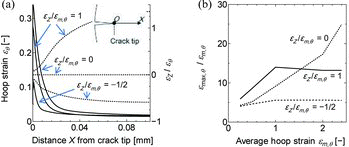
compares hoop strains calculated under different stress states around the tip of a 100-μm crack in a wall of 570 μm thickness, to explain the low failure strain in the plane strain case. The damage model was not used here, for simplicity. The hoop strain distributions at a load state with ϵm,θ = 2% is shown in (a) (solid curves), where ϵm,θ represents the circumferentially averaged hoop strain at the mid-wall of the cladding. The plane strain case (ϵZ/ϵm,θ = 0) shows much larger strain near the crack tip (X = 0) than the uniaxial tension case (ϵZ/ϵm,θ = −1/2), where ϵZ represents the axial strain. Variations of strain concentration ϵmax,θ/ϵm,θ with increasing ϵm,θ are shown in (b), where ϵmax,θ is the peak value of the local hoop strain ϵθ around the crack tip. In the given range, the stress concentration in the uniaxial tension case reaches a plateau, while it monotonically increases in the plane strain case. The low failure strain in the plane strain case (see ) is thus attributed to the more intense strain concentration than that produced in the original uniaxial tension case.
Figure 5. Hoop strains calculated under different stress states around the tip of a 100-μm crack in a wall of 570 μm thickness: (a) hoop strain distributions at ϵm,θ = 2% and (b) variations of strain concentration with increasing hoop strain ϵm,θ.
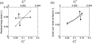
shows the sensitivity of the failure strains at 300 K to the damage parameters and
, calculated in the burst test and the RAG–EDC test analyses. The comparison between (a) and (b) shows that the sensitivity to each of the parameter
and
strongly depends on the mechanical test type. Owing to this dependency, the best-fit parameters for 300 K could be determined uniquely by improving the agreement of the failure strains between the analyses and the measurements. Conversely, the different sensitivities suggest the necessity of individually treating the two damage processes, damage initiation and evolution, for establishing a robust model for failure prediction that is applicable to different stress states and different types of specimens.
2.2.3. Burst test at 620 K with nonhydrided and hydrided specimens
The aforementioned burst test provides data at 620 K as well [Citation6]. The estimated residual hoop strain of the nonhydrided sample, about 13%, was used for determining the damage parameters. The burst test analysis at 620 K was conducted with the same model as that described in Section 2.2.1.
There was no available data from the RAG–EDC test conducted at high temperature. The burst test data of the cladding specimens with hydride rims [Citation6] were hence utilized instead of RAG–EDC test data. A hydride rim was modeled as a crack as in (c) and the reported hydride rim thickness was substituted for the crack length. The estimated residual hoop strain of the sample with a 110 μm hydride rim thickness, about 2%, was used for determining the damage parameters. The burst test analysis with the pre-cracked specimen was conducted with θd = π/20, a mesh size of L = 10 μm in the damage region, and plane strain loading.
The analysis with the best-fit parameters showed a rough agreement with the burst test results: about 13% and 1% of residual hoop strains for the smooth specimen case and the 110-μm-crack case, respectively. Note that the parameters for 620 K, based on the tests with the hydrided specimens, are less reliable than those based on the RAG–EDC test because of the uncertainty in the determination of the pre-crack length and possible influences of hydride precipitates.
2.2.4. Applicable stress state range for identified model parameters at 300 K
In general, the damage parameters may be dependent on the stress state. Recently, Fukuda et al. conducted a biaxial stress test, a kind of tube-burst test that enabled them to conduct the test on CWSR Zry-4 specimens at room temperature with various hoop/axial stress ratios [Citation8]. From the online strain measurements with strain gauges, the hoop strains at failure were not much different between the stress states of ϵZ/ϵm,θ = 0 and ϵZ/ϵm,θ = 1. This result suggests that the present value of , which was determined mainly by the burst test results (see (a)), is valid for the stress state range from ϵZ/ϵθ = 0.0 to 1.0, although it may need to be refined after the result of the post-test examination of the residual strain is reported.
The stress state in the RAG–EDC test is close to uniaxial tension, and so the strain concentration at the crack tip is less intense than that under plane strain loading (see ). However, ϵZ/ϵθ (the broken curves in (a)) approaches to zero at X = 0, indicating that the damage process around a crack tip should occur at a stress state rather close to plane strain loading irrespective of the stress state away from the crack tip. The model parameters given in are thus considered to represent the damage properties under a stress state close to plane strain loading, specifically ϵZ/ϵθ ≈ −0.1 (see the broken curve for ϵZ/ϵm,θ = −1/2 at X = 0 in (a)). The present parameters are hence considered to be applicable to cracked structures irrespective of the macroscopic stress state, unless the dependencies of the parameters on the stress state are significant in the ϵZ/ϵθ range roughly from −0.1 to +0.1 (see the broken curves for ϵZ/ϵm,θ = 1 and −1/2 at X = 0 in (a)). In any case, further verification of the parameters using the data from the tests with pre-cracked specimens under different stress states, e.g. ϵZ/ϵm,θ = 0 and = 1, is desired.
3. Application of the damage model to RIA-simulated experiments at the NSRR
3.1. RANNS calculation on RIA-simulated experiments at the NSRR
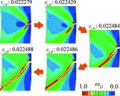
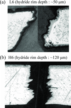
Pulse irradiation experiments simulating RIA conditions were previously performed on unirradiated test fuel rods consisting of fresh UO2 pellets and Zry-4 cladding with a hydride rim, for the purpose of simulating the failure behavior of high-burnup PWR-fuel claddings [Citation3]. The appearances of the cladding fractures were similar to those in the high-burnup PWR fuel tests [Citation1,2], characterized by the brittle cracking zone in the peripheral hydride rim region and the ductile shear zone in the inner side of the cladding wall, as shown in .
Figure 7. Fracture appearances of the claddings in the NSRR tests L6 and H6: horizontal cross sections of the fuel cladding around the fracture positions.
Before analyzing the experiments with the damage model, a preparative analysis was performed to estimate the cladding failure strain for comparison with the prediction from the damage analysis, and to identify the temperature distribution and the stress state in the cladding wall during the experiment. The failure strain was defined as the cladding-inner-surface hoop strain calculated at failure time, which had been determined by the spike signal in the transient record of the test-capsule pressure sensor. Out of the six test cases in which fuel failure occurred, the present study examined the three cases in which the pressure sensors worked successfully: tests L5, L6, and H6 [Citation3].
The preparative analysis was performed using the RANNS code, which analyzes the thermal and mechanical behavior of a single fuel rod in accident conditions [Citation4]. The code shares the basic framework and a major part of the modules with the FEMAXI-7 code, for normal operation conditions [Citation9]. summarizes the material properties and models employed in the RANNS calculation [Citation9,Citation14–20].
Table 2. Summary of the RANNS calculation conditions.
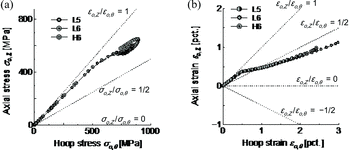
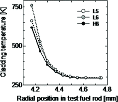
The RANNS calculation gave cladding failure strains of 1.4%, 2.0%, and 1.3% for tests L5, L6, and H6, respectively. (a) and (b) show the evolution of the axial stress with increasing hoop stress and the axial strain with increasing hoop strain, respectively, in the cladding periphery. The calculation gives similar evolutions for the three cases. The stress and strain biaxialities lie between those under plane strain loading and those under equibiaxial tension, i.e. the stress state of equal tensions between the hoop and the axial directions. shows the radial profiles of the cladding temperatures at failure time. While the outer surface temperatures remain low, the inner surface temperatures reach 600–750 K.
3.2. Simulation of PCMI failure and discussion
3.2.1. Calculation conditions
Eleven calculations were conducted; the cases are identified by Dm0.5F, D0.0F, D0.5F, D1.0F, P0.0F, P0.5F, P1.0F, D0.0G, D1.0G, P0.0G, and P1.0G.
The letter “D” in the case IDs represents a loading condition that dR (see (a)) was introduced as a forced displacement of the cladding inner surface. This loading condition is equivalent to an assumption that the fuel pellet expands keeping its circular outer surface shape and the cladding inner surface is bonded to the pellet outer surface throughout the calculation. In reality the cladding inner surface can partly separate from the pellet outer surface, and the fuel pellet is not a rigid body. It is hence not clear if this assumption is still valid after the initiation of crack propagation.
The letter “P” represents a loading condition used to simulate the PCMI loading more accurately. A pellet was introduced into the model as a cylinder with Young's modulus 200 GPa, Poisson's ratio 0.342, height LZ (see (b)), and the same radius as the cladding inner radius. The friction coefficient between the pellet and the cladding was set to be 1.0 and 0.0 in the hoop and the axial directions, respectively. Isotropic expansion, increasing linearly with time, was applied to the pellet. The cladding inner radius increase dR was then introduced via mechanical contact with the pellet outer surface.
The numerical figure in the middle of the IDs specifies the value of ϵZ/ϵi,θ in the calculation, where ϵi,θ represents the cladding hoop strain at the inner surface. For example, the values of ϵZ/ϵi,θ are equal to 0.0 and −0.5 in the cases D0.0F and Dm0.5F, respectively. The value ϵZ/ϵi,θ = 0.5 corresponds to a biaxial stress state similar to that in the NSRR tests (see (b)).
The cladding temperature was initially set to be 300 K with a flat profile. The letter “F” in the IDs represents a temperature condition that the initial temperature was maintained throughout the calculation. The letter “G” represents a temperature condition that the temperature gradient at failure time (see ) was applied to the cladding just after the FEM calculation started; the profile of test L6 was used since it gave the highest temperature level of the three test cases.
3.2.2. PCMI failure simulated with the damage model
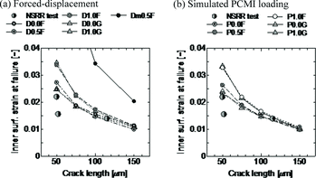
compares the cladding inner surface strains at failure from the damage analysis with those determined by the preparative RANNS calculation. In the latter case, representing the NSRR test results, the hydride rim thicknesses [Citation3] are substituted for the crack lengths in the plot. As such, it should be noted that there could be considerable uncertainties in the “crack length” in the latter case. For instance, a hydride rim thickness of more than 70 μm was reported in the reference [Citation3] for the test L4 case with a hydrogen content similar to the tests L5 and L6. Considering the uncertainty, the cases with ϵZ/ϵi,θ = 0.0–0.5 appears to be in reasonable agreement with the NSRR test results. The cases with ϵZ/ϵi,θ = 1.0 give larger failure strains than the cases with ϵZ/ϵi,θ = 0.0–0.5, by about 30% and 20% in the 50- and 100-μm-crack cases, respectively. The case with ϵZ/ϵi,θ = −0.5, close to uniaxial tension, conspicuously overestimates the experimental results. The comparison between (a) and (b) shows that the failure strains are not affected by the loading condition, forced displacement or simulated PCMI loading. The variation in the failure strains when introducing a temperature gradient is less than 5% for the investigated conditions.
Figure 10. Cladding inner surface strains at failure calculated with the damage model compared to the NSRR test results.
shows the simulated fracture appearances of the pre-cracked claddings in the cases D0.0F, D1.0F, and P0.0F. The simulated crack appears to be more inclined to have a straight propagation along the crack plane in the cases D0.0F and D1.0F than those experimentally observed (see ). On the other hand, case P0.0F, with the PC mechanical contact model, shows a more similar appearance to those observed: the predominant ductile shear in the shallow crack case (L6) and the straight crack propagation followed by small ductile shear in the deep crack case (H6). Hence, the PCMI loading driven by pellet thermal expansion is thought to play an important role in the formation of the fracture appearances specific to the PCMI failure.
Figure 11. Simulated fracture appearances of the pre-cracked claddings in cases D0.0F, D1.0F, and P0.0F.
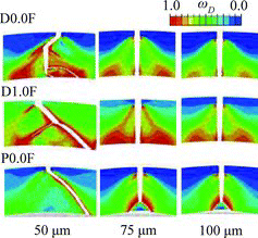
The comparison in indicates some deficiency of the displacement-controlled analysis in simulating the crack penetration processes, but the calculated failure strains are not sensitive to the loading conditions as shown in . We therefore believe that the occurrence of a through-wall crack is determined at an early stage of crack propagation that occurs in the cladding periphery, and the rest of the through-wall penetration process is achieved with a negligible strain increment, as visualized in .
3.2.3. Effects of the stress state
The larger failure strains of case D1.0F compared to that of case D0.0F (see ) is attributed mainly to the less intense strain concentration at the crack tip under equibiaxial tension than that under plane strain loading (see ). compares the evolution of the state variables ωD and D at the tip of a 50-μm crack with increasing cladding inner radius for the two cases. The evolution of the damage process in the D0.0F case is at first slower than that in the D1.0F case, becoming faster before the damage initiation (ωD = 1.0), and finally reaching D = 1.0 earlier than that in the D1.0F case. Such evolutions correspond to those of the strain concentrations under plane strain loading and equibiaxial tension shown in (b).
Figure 13. Evolutions of the state variables ωD and D at the tip of a 50-μm crack with increasing cladding inner radius, in the cases D0.0F and D1.0F.
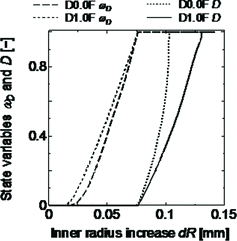
This result suggests that the failure strains of a cracked specimen under equibiaxial tension can be different from that under plane strain loading if the damage property does not depend on the stress state. Note that the degree and the tendency of the stress-state effects on the failure strain can vary not only with the damage parameters but also with the employed elastoplastic constitutive model. As the Le Saux model expresses plastic anisotropy enhanced with irradiation, a different result could be found in the high-burnup fuel claddings.
Glendening et al. reported that the failure strains of the specimens with hydride blisters under equibiaxial tension were similar to those under plane strain loading [Citation21]. The different conclusion reached with the present analysis could be attributed to the difference in the geometry of cracks, if it is not caused by the imperfections in the damage parameters or the constitutive model. We assumed a crack that runs along the cladding axial direction, leading to the stress state close to plane strain loading around the crack tip. In contrast, the damage process in their test could have occurred mainly under equibiaxial tension because of the “mud-cake” cracks that formed normal to the multidirectional orientation of the maximum principal stresses [Citation21].
3.2.4. Effects of cladding local temperature rise
Introducing a temperature gradient did not affect significantly the strain concentration around the crack tip. While the fracture appearances sometimes changed, reflecting enhanced ductility in the inner part of the cladding, the resultant variation in the failure strains was very small (see ). The effect of the introduced temperature gradient on the failure limit is hence not considered significant despite the steep temperature gradient and the strong positive correlation of the damage parameters with temperature (see ).
Tomiyasu et al. pointed out that the failure limit apparently depended on the cladding average temperature and then suggested that temperature rise in the inner part of the cladding could contribute to an increase in the failure limit [Citation3]. However, the above results obviously contradict their suggestion. For example, the average temperature calculated from the profile shown in is about 380 K, which is higher by about 80 K than that of the 300 K flat temperature case. A PCMI failure of a cladding specimen with a 50-μm crack was then simulated under the imaginary temperature condition of a flat profile at 380 K. The calculated failure limit, i.e. failure strain, was larger by about 30% than those in the temperature gradient case. If the average temperature was relevant to the failure limit, the imaginary 380 K case would give a failure strain comparable to that calculated in the temperature gradient cases. Consequently, averaging the cladding radial temperature to use as a reference for cladding ductility can lead to significant overestimation of the effect of ductility enhancement with temperature rise under RIA conditions.
4. Conclusions
The present continuum damage mechanics model demonstrated that the PCMI failure processes from initiation of the crack propagation to the formation of a through-wall crack can be computationally reproduced by assuming an incipient crack in the cladding periphery. The analysis not only gave reasonable predictions regarding the cladding hoop strain at failure but also reproduced the typical fracture behavior of the fuel cladding under PCMI loading, characterized by a ductile shear zone in the inner side of the cladding wall. It was shown that the occurrence of a through-wall crack is determined at an early stage of crack propagation that occurs in the cladding periphery, and the rest of the through-wall penetration process is achieved with a negligible strain increment.
The sensitivity analysis of the cladding stress state showed that the plane strain condition can be a more severe stress state, with more intense strain concentration at the crack tip, leading to smaller failure strains by at most 20%–30% than for the equal tensions between the hoop and axial directions. The effect of a local temperature rise in the cladding inner region on failure strain was found to be less than 5% for the investigated conditions, suggesting that neither the inner wall temperature increase nor the average temperature increase is relevant to an increase in the PCMI failure limit. These results provide an important basis for evaluating the applicability of the data and knowledge of PCMI failure obtained in the mechanical tests and the RIA-simulated experiments to the power reactor conditions.
Acknowledgements
The FEM calculations presented were performed on the supercomputer Primergy of the Japan Atomic Energy Agency. The authors are indebted to the engineers, technicians, and researchers at JAEA working on the NSRR experiments.
References
- Fuketa T, Sugiyama T, Nagase F. Behavior of 60 to 78 MWd/kgU PWR fuels under reactivity-initiated accident conditions. J Nucl Sci Technol. 2006;43:1080–1088.
- Fuketa T, Sasajima H, Sugiyama T. Behavior of high-burnup PWR fuels with low-tin Zircaloy-4 cladding under reactivity-initiated-accident conditions. Nucl Technol. 2001;133:50–62.
- Tomiyasu K, Sugiyama T, Fuketa T. Influence of cladding-peripheral hydride on mechanical fuel failure under reactivity-initiated accident conditions. J Nucl Sci Technol. 2007;44:733–742.
- Suzuki M, Saitou H, Fuketa T. Analysis of pellet-clad mechanical interaction process of high-burnup pwr fuel rods by RANNS code in reactivity-initiated accident conditions. Nucl Technol. 2006;155:282–292.
- Dassault Systemes Simulia Corp. Abaqus 6.11 analysis user's manual. Providence (RI): Dassault Systemes Simulia Corp.; 2011. Chapter 23, Progressive Damage and Failure.
- Nagase F, Fuketa T. Investigation of hydride rim effect on failure of Zircaloy-4 cladding with tube burst test. J Nucl Sci Technol. 2005;42:58–65.
- Fukuda T. Development of pre-cracked cladding specimen for PCMI failure study. Paper presented at: Fuel Safety Research Meeting 2010; 2010 May 19–20; Tokai, Japan.
- Fukuda T. The cladding fracture behavior under biaxial stress condition. IAEA-TECDOC-CD-1709. Mito (Japan): International Atomic Energy Agency; 2011.
- Suzuki M, Saitou H, Udagawa Y. Light water reactor fuel analysis code FEMAXI-7; model and structure. JAEA-Data/Code 2010-035. Ibaraki (Japan): JAEA; 2010. Japanese.
- Le Saux M, Besson Z, Carassou J, Poussard S, Averty X. A model to describe the anisotropic viscoplastic mechanical behavior of fresh and irradiated Zircaloy-4 fuel claddings under RIA loading conditions. J Nucl Mater. 2008;378:60–69.
- Hillerborg A, Modder M, Petersson PE. Analysis of crack formation and crack growth in concrete by means of fracture mechanics and finite elements. Cement Concrete Res. 1976;6:773–781.
- Grange M, Besson J, Andrieu E. An anisotropic Gurson type model to represent the ductile rupture of hydrided Zircaloy-4 sheets. Int J Fracture. 2000;105:273–293.
- Desquines J, Koss DA, Motta AT, Cazalis B, Petit M. The issue of stress state during mechanical tests to assess cladding performance during a reactivity-initiated accident (RIA). J Nucl Mater. 2011;412:250–267.
- Siefken LJ, Coryell EW, Harvego EA, Hohorst JK. SCDAP/RELAP5/MOD3.3 code manual: MATPRO – a library of material properties for light-water reactor accident analysis. NUREG/CR-6150. Washington (DC): US Nuclear Regulatory Commission; 2001.
- Hagrman DL, Reymann GA. MATPRO-VERSION 11: a handbook of materials properties for use in the analysis of light water reactor fuel rod behavior. NUREG/CR-0497. Washington (DC): US Nuclear Regulatory Commission; 1981.
- Ohira K, Itagaki N. Thermal conductivity measurements of high burnup UO2 pellet and a benchmark calculation of fuel center temperature. Paper presented at: Proceedings of the ANS Topical Meeting on Light Water Reactor Fuel Performance; 1997 Mar 2–6; Portland, OR. p. 541–549.
- MacDonald PE, Thompson LB. MATPRO: version 09. A handbook of materials properties for use in the analysis of light water reactor fuel rod behavior. TREE-NUREG-1005. Washington (DC): US Nuclear Regulatory Commission; 1976.
- Ross AM, Stoute RL. Heat transfer coefficient between UO2 and Zircaloy-2. CRFD-1075. Ontario (Canada): Atomic Energy Commission of Canada Limited; 1962.
- Tachibana T, Furuya H, Koizumi M. Effect of temperature and deformation rate on fracture strength of sintered uranium dioxide. J Nucl Sci Technol. 1976;13:497–502.
- Geelhood KJ, Luscher WG, Beyer CE, Cuta JM. FRAPTRAN 1.4: a computer code for the transient analysis of oxide fuel rods. NUREG/CR-7023. Washington (DC): US Nuclear Regulatory Commission; 2011.
- Glendening A, Koss DA, Motta AT, Pierron ON, Daum RS. Failure of hydrided Zircaloy-4 under equal-biaxial and plane-strain tensile deformation. J ASTM Int. 2005;2:833–848.

