Abstract
This study describes a multi-resolution analysis (MRA) to determine the onset and end drop times of control rods. The measurement test of the drop times of control rods is normally performed during the start-up test of each reactor cycle since it is a crucial safety function to guarantee the reactor safe shutdown. The MRA with wavelet transform is particularly useful in analyzing the onset transients of rod drop as a means of capturing the unique attributes of such signals in an efficient way. This approach also allows the automated determination of rod drop time which reduces the uncertainty induced by ad hoc heuristic approaches. The test signal is generated by adding the random noise measured from real rod drop tests subtracting the wavelet-filtered noise free signal from the noisy signal leaving the noise. The signal is similar to both high sharp spikes noise and sine wave noise from the real voltage trace generated during the rod drop test. The effectiveness of the method is demonstrated by the MRA process.
1. Introduction
Nuclear reactors contain control rod drive system to regulate the overall reactor power level, power distribution and to provide the principal means of quickly and safely shutting down the reactor. The rods are vertically moving by the drive mechanism that provides both positioning and latching functions, and a reactor trip function. The reactor is shut down by fully inserting or dropping the control rods into the reactor core. Rod drop time (RDT) measurement test is to check the time period required for the control rods to reach fully inserted position from the initiation of a reactor trip signal [Citation1]. Technical specifications require the RDTs be less than some minimum specified time in the case of reactor trip. These tests are usually conducted as a critical path after periodic maintenance and refueling to assure that the reactor has been properly reassembled. If RDTs measured from a test do not meet the time limit of technical specification, the nuclear power plant cannot resume the next fuel cycle operation. When a ferromagnetic control rod drive shaft falls through inside electromagnetic coils, voltages are induced from these coils. The voltage signals contain both low- and high-frequency components generated during the rod drop from its maximum withdrawn position to a fully inserted position. The mechanism of control rod drop behavior is proposed based on a non-linear differential equation to study the effects of isolated parameters on scram time [Citation2]. A more detailed numerical simulation method [Citation3] is proposed to describe the insertion or drop of the rod cluster control assembly. A review is presented on anomalies and conditions of increase in drag force slowing down the RDT with many kinetic measurement data [Citation4].
The wavelet application for black box models for monitoring operational parameters in a complex system [Citation5] and computing the probability density functions associated with different system states in a nuclear environment [Citation6] are the beginning of proposals for wavelet-based process monitoring in the nuclear engineering field. A review paper on the transient identification in nuclear power plants [Citation7] gives a comprehensive survey on the application of artificial neural networks, fuzzy logic, genetic algorithm and other soft-computing techniques but includes very limited reference on wavelet implementation. An investigation on reactor condition monitoring and singularity detection via wavelet transform is proposed [Citation8], and one can find a comprehensive wavelet application references therein. It is also proposed to apply wavelet transform of the reactor signals to monitor the moderator coefficient of reactivity [Citation9]. The demonstration of de-noising filter performance is described in [Citation10] comparing wavelet and bilateral kernel filters. The wavelet-based acoustic leak detection method is proposed and applied for the detection of the reactor-inlet feeder pipes [Citation11]. The stability parameter analysis and monitoring of boiling water reactors are other application areas of wavelet method [Citation12,13].
This study provides a method for determining RDT on the basis of multi-resolution wavelet analysis [Citation14] to identify discontinuities and sharp spikes among noisy voltage trace. The theoretical objective of this study is to demonstrate a method to decide the precise onset and end time of rod drop transient. Normally the signal on the onset period of the transient is highly noise contaminated, which makes it difficult to measure precise start time. The end point of the transient signal shows not a steep breakpoint which makes it not easy to discriminate. The five levels of wavelet decomposition are introduced to separate the signal into approximations (noise-filtered signal) and details (DC-component eliminated signal) for visual and automatic identification of onset and end points of the signal. This study uses the Harr wavelets because of its effectiveness of short wavelets compared with long ones in detecting a signal rupture. This method makes wavelet-based discontinuity detection more accurate and robust than threshold or curve-fitting-based detection methods.
2. Characteristics of voltage signal during rod drop time test
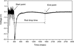
The electromagnetic coils, called a lift, a movable and a stationary coil, are installed in the control rod drive system to manipulate magnetic-jack type latches to insert and withdraw a rod. When a control or shutdown rod is dropped from a fully withdrawn position, a ferromagnetic control rod drive shaft is passing through the coils such that magnetic flux change causes the coils to induce voltages associated with the rod drop. The induced voltage trace with respect to time recorded at each coil is used to calculate a RDT. The voltage trace generated from the movable coil is drawn on an enlarged scale in .
The movable coil voltage abruptly decreases as soon as the rod drop is initiated. This sudden decrease is caused by the self-induction of stationary coil current. As the predominant voltage signal due to the self-induction almost disappears, the total voltage induced from the movable coil reaches the maximum voltage point. When a control rod reaches the dashpot, its falling velocity decreases abruptly, a kind of damping behavior appears because the dashpot is designed to absorb the energy of a rod falling motion. This phenomenon is exhibited in the movable coil voltage in the form of slope change such that a sign of its slope changes from negative to a positive direction at the dashpot entry point. The dashpot entry point represents a reference point for RDT calculations of the rod dropped. A magnitude of the voltage signal at the point has a second minimum value. Conclusively, a RDT is calculated from the movable coil voltage by finding the dashpot entry point, where a sign of slopes changes from negative to positive after passing the point where the influence of the self-induction of the stationary coil disappears. Unfortunately, the voltage signals contain both low-frequency components and high-frequency components generated during the rod drop. The noise characteristics of voltage signals are different in the first time period which is before the rod drop, and in the second time period which is after the rod drop. The signals in the first time period contain the sharp spikes noises with high frequency and the signals in the second time period contain the sine wave noises with low frequency as shown in .
Once a voltage trace is obtained, technical staff manually finds the point at which a rod reaches the dashpot by picking a point where its induced voltage shows an abrupt, rapid drop in the graph with respect to time. It is sometimes difficult to accurately find a point of abrupt voltage drop, which may result in an inaccurate RDT calculation. Also, the conventional method requires much time and labor for RDT calculation in multiple tests.
3. Multi-resolution analysis of RDT determination
Wavelet transform is a mathematical tool which can be used to extract information from many different kinds of signals and images. Wavelet transform is a domain transform technique for hierarchical decomposition. It allows a sequence to be described in terms of an approximation of the original sequence, plus a set of details that range from coarse to fine. A wavelet transform is the representation of a function by wavelets. The property of wavelets is that the broad trend of the input sequence is preserved in the approximation part, while the localized changes are kept in the detail parts. For short, a wavelet is a smooth and quickly vanishing oscillating function with good localization properties in both frequency and time. Wavelet transforms have advantages over traditional signal transform techniques for representing functions that have discontinuities and sharp peaks, and for accurately deconstructing and reconstructing the transient signals. To demonstrate the effectiveness of the wavelet representation of transient signals, we adhere the excellent derivation by Mallat [Citation14].
The basis waveforms Ψj, k form a set of orthogonal functions derived from scaling and translations of a mother wavelet,
1
Any function can be represented in terms of this orthogonal basis as
2 where cj, k = ⟨Ψj, k(t), f(t)⟩ are called the wavelet coefficients of f(t).
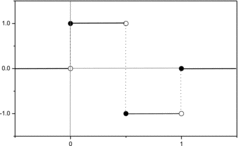
The Haar wavelet, the simplest and the oldest of all wavelets, has the fastest transform algorithm and is the most popularly used orthogonal wavelet. This study uses the Haar wavelet because short wavelets are often more effective than long ones in detecting a signal rupture. In the initial analysis scales, the support is small enough to allow fine analysis. The shapes of discontinuities that can be identified by the smallest wavelets are simpler than those can be identified by the longest wavelets. Conceptually, the Harr mother wavelet functions are analogous to the impulse response of a band-pass filter as shown in .
The Haar wavelet's mother wavelet function Ψ(t) can be described as
3 and its scaling function φ(t) can be described as
4
To efficiently calculate the wavelet transform for transient signal processing, Mallat introduced the multi-resolution analysis (MRA) method and designed a family of fast algorithms [Citation14]. Signals usually contain both low-frequency components and high-frequency components. Low-frequency components vary slowly with time and require fine frequency resolution but coarse time resolution. High-frequency components vary quickly with time and require fine time resolution but coarse frequency resolution. Therefore, MRA is useful for identifying peaks and valleys of noisy signals that contain both low- and high-frequency components.
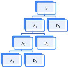
Because the reconstruction procedures of Haar wavelets are hierarchical, Haar coefficients can be divided into two parts, the principal part which includes the first few coefficients contains an overall approximation of the data and the detailed part which contains the additional coefficients. At a given resolution, a signal is approximated by ignoring all fluctuations below that scale. We can progressively increase the resolution: finer details are then added to the coarser description, providing a better approximation of the signal. In MRA, a signal is split into an approximation and a detail as shown in . The approximation is then itself split into a second-level approximation and detail, and the process is repeated. For an n-level decomposition, there are (n+1) possible ways to decompose or encode the signal.
The signal can be represented using the following equation:
5 where S denotes original signals, A denotes the approximation coefficients and D denotes the detail coefficients. The approximation coefficients contain low-frequency information and the detail coefficients have high-frequency information such as edges or discontinuities.
In this study, we performed the MRA on the voltage trace induced during a rod drop to determine two points that represent the initiation and finish of the rod drop. Because the wavelet transform level affects the degree of smoothness and the location of the discontinuity in a signal, we determined five levels of wavelet transforms through the initial testing to find the optimum level. The signals in the first time period contain the sharp spikes noises with high frequency, and the signals in the second time period contain the sine wave noises with low frequency as shown in . The more general definitions of onset, transient and the detection of peaks with wavelet signal processing can be found in [Citation15].
The MRA algorithm is implemented with the validated MATLAB® Wavelet Toolbox [Citation16] using the wavelet decomposition and reconstruction functions for MRA.
4. Results
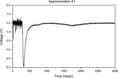
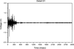
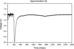
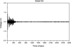
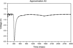
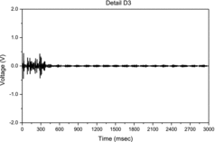
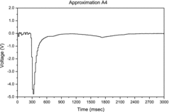
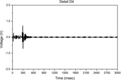
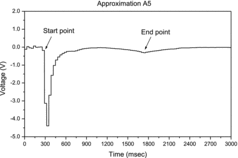
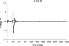
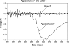
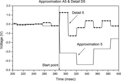
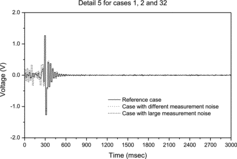
In this study, the effectiveness of the MRA algorithm is proposed with the simulated signal containing the random noise with both high sharp spikes noise and sine wave noise from the real voltage trace generated during the rod drop. The MRA algorithm is applied to show its robustness and accuracy. The process for determining the RDT is divided into five stages with five levels of wavelet decompositions. As in Equation (5), the approximation An becomes lower frequency signal with more detail Dn as n, the decomposition level, increases and identifies the same temporal instants. Figures – show the level 1 to level 5 MRA results of approximations and details, respectively. With increasing the MRA levels from 1 to 5, the large noise fluctuations on the onset point decrease and make it easy to identify the starting and end point of the transient. and show the point with crisp value in fifth-level detail (D5) which gives the discontinuity most clearly and represents the initiation time of the rod drop The signal rupture contains the high-frequency part and the signal undergoes abrupt changes such as a jump, or a sharp change. The end point, the dashpot entry, of the transient is easily identified with the level 5 approximation (A5), since it has a large signal-to-noise ratio.
and are the graphs presented on an enlarged scale of approximation and detail of the level 1 and level 5. shows the discontinuity localized very precisely compared with : only a small domain around point of 289 msec.
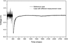
To demonstrate the performance of the algorithm, we consider a set of rod drop test observations made at a nuclear power plant. Fifty five test signals are generated by using the random noise measured from real 55 rod drop tests subtracting the wavelet-filtered noise free signal from the measurements leaving the noise. The signal is similar to both high sharp spikes noise and sine wave noise from the real voltage trace generated during the rod drop test. For the sake of illustrative purpose, only one trace record (reference signal) is considered and 55 cases with different measurement noises are added to that reference signal. The object of this demonstration is to show the accuracy and robustness of the proposed algorithm giving a consistent estimation result regardless of the noise characteristics.
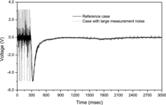
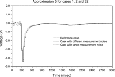
shows the reference signal with different measurement noises and is the reference signal and the case with large measurement noise typically in the beginning stage.
The effectiveness of the proposed MRA can be shown by comparing the wavelet processed signals in and . The figures show the consistent results irrespective of the magnitudes of measurement noise. The approximation 5 and detail 5 for signals present no big differences to discriminate the start and end times of the transients.
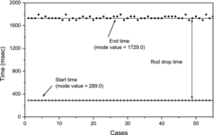
shows the consistent result of measuring the RDT for 55 cases of different measurement noises. The start time is precisely estimated as the mode value of 289.0 msec and the end time is estimated as the mode value of 1729.0 msec with the maximum error of 64 msec for all the 55 cases.
5. Conclusion
It is shown that the MRA based on Haar wavelet to determine the onset and end time of control rod drop is particularly useful. The MRA is composed of five levels of signal decomposition into approximations and details. The effectiveness of the method is demonstrated by simulated signal added with the measured random noise at the real power plant. The application results of the proposed method give very crisp identification of the onset and end points of the control rod drop transient under sharp spikes noise condition. The method can be an effective way to provide a mean to guarantee the quick and safe shut down function of the nuclear reactors.
References
- Kim K, Yoon M, inventors. Method for measuring control rod fall time using electromagnetic coil winding in reactor control. Japan patent JP 1999-194196. 1999.
- Donis J, Goller H. A mathematical model of a control rod drop. Nucl Eng Des. 1972;23:107–120.
- Andriambololona H, Bosselut D, Massin P. Methodology for a numerical simulation of an insertion or a drop of the rod cluster control assembly in a PWR. Nucl Eng Des. 2007;237:600–606.
- Collard B. RCCA drop kinetics test, calculation and analysis. Abnormal friction force evaluation. Paper presented at: Proceedings of the Seventh International Conference on Nuclear Engineering; 1999 Apr 19–23; Tokyo, Japan.
- Ikonomopoulos A. Wavelet decomposition and radial basis function networks for system monitoring. IEEE Trans Nucl Sci. 1998;45:2293–2301.
- Ikonomopoulos A, Endou A. Wavelet application in process monitoring. Nucl Technol. 1999;125:225–234.
- Moshkbar-Bakhshayesh K, Ghofrani M. Transient identification in nuclear power plants. Prog Nucl Energy. 2013;67:23–32.
- Kim O, Cho N, Park C, Park M. Investigation of reactor condition monitoring and singularity detection via wavelet transform and de-noising. Nucl Eng Technol. 2007;39:221–230.
- Shimazu Y. A feasibility study on wavelet transform for reactivity coefficient estimation. J Nucl Sci Technol. 2000;37:1009–1014.
- Park M, Shin H, Lee E. Kernel-based noise filtering of neutron detector signals. Nucl Eng Technol. 2007;39:1–6.
- Shimanskiy S, Iijima T, Naoi Y. Development of acoustic leak detection and localization methods for inlet piping of Fugen nuclear power plant. J Nucl Sci Technol. 2004;41:183–195.
- Espinosa-Paredes G, Prieto-Guerrero A, Nunez-Carrera A, Amador-Garcia R. Wavelet-based method for instability analysis in boiling water reactors. Nucl Technol. 2005;151:250–260.
- Espinosa-Paredea G, Nunez-Carrera A, Prieto-Guerrero A, Cecenas M. Wavelet approach for analysis of neutronic power using data of Ringhals stability benchmark. Nucl Eng Des. 2007;237:1009–1015.
- Mallat S. A theory of multiresolution signal decomposition: the wavelet representation. IEEE Trans Pattern Recognit Mach Intell. 1989;11:674–693.
- Bello J, Daudet L, Abdallah S, Duxbury C, Davies M, Sandler M. A tutorial on onset detection in music signals. IEEE Trans Speech Audio Process. 2005;13:1035–1047.
- Misiti M, Misiti Y, Oppenheim G, Poggi J. Wavelet toolbox for use with MATLAB® user's guide. Natick (MA): The MathWorks, Inc.; 1997.

