Abstract
Utilization of rock-like oxide (ROX) fuel in light water reactors for plutonium (Pu) burning was studied by nuclear material balance (NMB) analysis for a case of Japanese phase-out scenario under investigation after the Fukushima accident. For the analysis, the NMB code was developed with features of accurate burn-up calculation, flexible combination of reactors and fuels, and an ability to estimate waste and repository. Three scenario groups of once-through Pu burning in mixed oxide (MOX) fuel and in ROX fuel were analyzed. Using two full-MOX or full-ROX reactors the Pu amount is reduced to about one-half and the isotopic vector of Pu deteriorated for being used as a nuclear weapon, especially in terms of spontaneous fission neutron generation. Effects of ROX reactors are more significant than MOX reactors in terms of both reduction in the Pu amount and deterioration of the isotopic vector. Repository footprint and potential radiotoxicity are not reduced by the MOX and ROX reactors because the heat and toxicity of MOX and ROX spent fuels are considerably high.
1. Introduction
If a nation phases out nuclear power generation after a long operation, it leaves behind a considerable amount of nuclear material which is no longer burnable in commercial nuclear power reactors. Nuclear power generation by operating only light water reactors (LWRs) with uranium fuel depletes uranium, plutonium (Pu) and a small amount of minor actinides (MAs) in the spent fuel (SF), whereas deploying a fleet of fast breeder reactors (FBRs) leads to larger amounts of Pu and MAs in the FBR SF than those in the case of LWRs. Following nuclear power generation, there are three options to treat these legacies: directly disposing the SF; transporting it to other regions; or burning it in dedicated transmutation systems. The first option would be economic, but it is difficult to find or construct a repository owing to the large footprint, stability of SF assemblies in the repository and possibility to retrieve the Pu for the purpose of manufacturing nuclear weapons. The second one is reasonable if there is requirement for Pu in the neighboring areas, but it highly depends on political circumstances and the nonproliferation concern will be the primary issue. Moreover, the last option does not make sense for the last nation in the row. The last option may prove costly but effective to confine radioactive nuclides to vitrified waste and minimize Pu inventory. There are two types of transmutation concepts: one is once-through transmutation without reprocessing of SFs from the transmutor and the other is multiple transmutation by reprocessing them [Citation1]. The former is utilization of LWRs with fuels of Pu and the latter is introduction of the fast reactor technology, including an accelerator-driven system. The latter is much more effective in terms of the transmutation ratio which can be more than 99%, but further research and development and more investment are required to serve the purpose.
In the present study, we adopt the last option, i.e. the transmutation option, in a country without the FBR technology, by analyzing Japanese nuclear material balance as an example. Results from the Japanese case can encourage countries like the USA, France, Germany, etc., which possess a considerable amount of SF and nuclear power plants (NPPs) under operation, if they consider to phase out nuclear power generation, although at different scales. After an experience of the Fukushima nuclear accident, Japan has started an investigation into the feasibility of doing away with the nuclear option by shutting down NPPs without any prolongation and reconstruction, in addition to adopting a conventional strategy to introduce FBRs to continue nuclear power generation. The remaining SF assemblies from LWRs can directly go to a repository, or can be reprocessed in the Rokkasho reprocessing plant (RPP) to be launched in the near future. Extracted Pu is supposed to be fabricated as mixed oxide (MOX) fuel burnable in LWRs. Instead of MOX fuel, rock-like oxide (ROX) fuel has been developed for the purpose of achieving better stability of SF and higher transmutation of fissionable Pu than MOX fuel [Citation2]. ROX fuel contains mainly Pu with less amount of 238U to reduce Pu production and to transmute about 90% of fissile Pu [Citation3,4]. ROX SF is chemically stable so radionuclides can be confined in a repository, and it is difficult to obtain Pu by reprocessing.
Three strategies, once-through of UO2, MOX transmutation and ROX transmutation, are investigated by a mass balance analysis code developed by authors, in terms of necessary loading to LWRs of MOX or ROX fuel assemblies, Pu and MA inventory, proliferation attractiveness and repository footprint. The analysis code is described in Section 2 and the assumptions of the scenario study in Section 3. Analysis results for each strategy are shown in Section 4 and discussed in Section 5. Conclusions are drawn in Section 6.
2. Scenario analysis code
2.1. Features and structure
To estimate the future material flow of heavy metals, the nuclear material balance analysis (NMB) code has been developed by the authors on a Microsoft Excel with VBA platform. The NMB code provides an estimate of the availability of actinides based on user-input data relating to NPP constructions every year and a reprocessing scheme. The salient features of the code are as follows:
Composition change during depletion in a reactor followed by storage of 26 actinides with half-lives longer than several days, including thorium to curium, is calculated by the exponential multiple method using one-group cross sections built in the code. The calculation accuracy is comparable to that of dedicated burn-up codes such as ORIGEN [Citation5].
The initial enrichment of the 235U or Pu content in fresh fuel is determined by an infinite multiplication factor (k-infinity) so that the Pu content can be made reasonably dependent on the Pu isotropic vector.
The appropriate fuel for different LWRs, the CANDU reactor, gas-cooled reactors, sodium-cooled fast reactors and lead-bismuth-cooled ADSs, such as UO2, MOX, ROX, Pu-nitride and MA-nitride, can be decided with the help of this code.
Fission products are estimated by dividing them into several groups (iodine, rare gas, technetium and platinum group metals, strontium, caesium and others) depending on the neutron spectrum (fast or thermal) and fission material (235U or 239Pu). Then, the number of waste packages and repository size are determined by temperature analysis, considering the repository layout. Potential radiotoxicity which is defined as dose by direct ingestion is also estimated.
Calculation time for each scenario in the present study is 5–10 minutes on an Intel i7 2.80 GHz CPU.
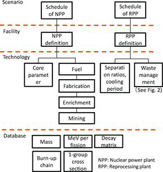
illustrates the layer structure of the NMB code. The top one is the “Scenario” layer in which the user can assume the numbers of NPPs to be constructed in each year, schedule of RPPs loading ratio of MOX fuel to LWRs, etc. Parameters of NPPs are predefined in the second “Facility” layer as a combination of a core parameter and kinds of fuel to be loaded. The RPP is also defined as a combination of a plant parameter and a waste management type. The third “Technology” layer is devoted to detailed parameters of each facility, for example, plant life, thermal efficiency, load factor, batch length and batch number as core parameters. In the third “Fuel” layer, a set of one-group cross section, power density and an upper limitation of Pu content are given. A notable parameter is k-infinity by which the 235U enrichment in UO2 fuel or Pu content in MOX fuel is determined. Because the Pu vector in MOX fuel changes due to uncertain burn history and cooling time, the Pu content cannot be predetermined. Determination using k-infinity results in a more reasonable approach. k-infinity is defined as a summation only for heavy metals without structural and coolant nuclides as given below:
(1)
Generally, low Pu content in MOX fresh fuel is caused by more fissionable Pu composition and results in a large drop of k-infinity after depletion, and vice versa. Therefore, determination based only on k-infinity of fresh fuel is not the appropriate method, but that based on an average of k-infinities of fresh fuel and SF is better. However, it requires many times of time-consuming depletion calculation and is not practical. Therefore, the NMB code employs k-infinity of fresh fuel as a default option.
The impact of other elements such as the clad and coolant is less than heavy metals in terms of dependency of k-infinity on Pu composition, because the geometry and number densities of other elements are not influenced by the composition. Moreover, the user did not need to collect the information of the other elements owing to excluding them.
The lowest layer is a database which is used for burn-up calculation.
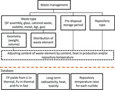
One of the unique features of the NMB code is precise estimation of the number of waste forms, size of a storage facility and repository footprint with consideration of heat production within the waste and repository temperature limitation. The code can also account for advanced wastes such as glass waste form with high-fission-product (FP) loading and calcined waste form with strontium and caesium. A methodology to determine the above for these advanced waste forms is described in Ref. [Citation6] and in the appendices for direct disposal of SF. As illustrated in , waste management is defined by the waste type to be produced, storage period and repository type such as vertical layout in crystalline rock, accumulated layout, etc. The NMB code estimates a content ratio of waste elements for wastes of different forms by limiting heat in the production facility and limiting temperature in the repository after predisposal storage for a preassumed storage period. The temperature in the repository is calculated through the NMB code with the help of a database containing information about temperature evolutions after disposal in each repository by a unit amount of each nuclide. Long-term radiotoxicity is also estimated.
After the user revised the predefined parameters of the facility and technology layers, and assumed schedules of NPPs and RPPs, the code starts calculation along the axis of time, from the beginning to the end. It estimates necessary amounts of fresh fuels, compositions of SFs by depletion analysis, production of raw materials and wastes from RPPs, and the repository footprint of the wastes.
2.2. Theory and validation of burn-up calculation
The NMB code employs the exponential multiple method for depletion and cooling calculation of selected 29 nuclides as listed in : 26 actinides, 99Tc, 129I and a bunch of other fission products. This method is employed in the ORIGEN-2 code [Citation5] for nuclides with long half-lives, while the Bateman method is used for ones with short half-lives.
Table 1. Nuclides in the NMB code.
The formula to obtain X that represents the nuclide amount is
(2) where t is time (s), N is the number of nuclides, D is a decay matrix (N × N), Cfiss, Ccap and C(n,2n) are the cross-section matrices of the fission, capture and (n, 2n) reactions, respectively, F = (fission cross section matrix) × (emission per fission (J)) and P is the total power of the reactor (W).
P/FX represents neutron flux in units of n/cm2/s. The elements of matrix D (a unique matrix) are decay constants of each nuclide. Other matrices, F, Cfiss, Ccap and C(n,2n), consist of one-group micro cross sections for each reactor, most of which are taken from the libraries of the ORIGEN-2 code [Citation7].
The solution of Equation Equation(2)(2) is given by the multiple expansion method employed in the ORIGEN-2 code:
(3) where I is a unit matrix and Δt is the time mesh (s).
The accuracy of the solution depends not only on the time mesh and expansion order of Equation Equation(3)(3) , but also on the estimation of matrix A which involves cross sections. In this study, an accuracy goal for this method with respect to time mesh and expansion order is supposed to be 1E–3, considering that the effect of cross sections is generally more significant.
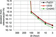
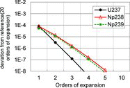
The effect of selecting a time mesh, Δt, on the accuracy is shown in where three nuclides with the largest errors among all are illustrated for an SF composition of FBR with 1% of MA. The deviation rapidly diverges for Δt longer than 100 h, because this method is not tolerant for Δt much longer than the shortest half-live, i.e. 2.1 d for 238Np. In the NMB code, Δt is fixed at 100 h corresponding to an error of 1E–9.
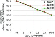
As shown in Equation Equation(2)(2) , matrix A is time-dependent because it contains the X vector and must be updated in an appropriate time interval. The interval has been fixed at 0.1 GWd/tHM (gigawatt-days/metric ton of heavy metal), as shown in , on account of which 1E–4 of relative error is achieved. The order of expansion in Equation Equation(3)
(3) is fixed at 3 according to where 1E–6 of relative error is attained.
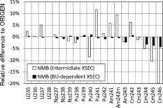
By setting the above time meshes and order, the numerical error of the exponential multiple method becomes less than 1E–3, but the inaccuracy of cross section due to fluctuation of the Pu vector and burn-up dependency is much more significant. A typical example of the dependency is the 240Pu capture reaction in LWRs. At the beginning of burn-up, 240Pu does not exist in a reactor and the capture cross section of 240Pu is large due to absence of the self-shielding effect. This cross section drops to about half of an initial value at the end of burn-up. illustrates a comparison of the NMB code with the ORIGEN code with and without the dependency using a library of a pressurized LWRs (PWRs) with 4.1% enrichment of 235U [Citation7]. In the ORIGEN code, a cross section set of the corresponding PWR fuel and a decay chain based on JENDL-3.2 [Citation7] were used similarly to the NMB code. The number of irradiation time steps was set to 20, resulting in a burn-up step of 2 GWd/tHM. In the NMB code, a cross section of intermediate burn-up, i.e. 26GWd/tHM, was employed in an “intermediate XSEC” case, while the dependency is taken into account in a “burn-up-dependent XSEC” case in which the difference from the ORIGEN code is less than 5%. Moreover, the difference of major nuclides is less than 1% which implies that the accuracies of the two codes are practically equal with respect to production of Pu from LWRs. The ORIGEN libraries are still updated based on the newly evaluated libraries.
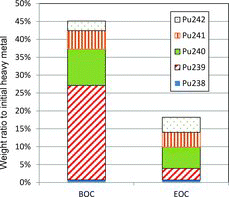
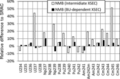
In the case of ROX fuel, an effect of the burn-up dependency is more significant than that in UO2 fuel because the composition change in ROX fuel after burn-up is more drastic. shows the change where 239Pu decreases by about 90% [Citation3]. The NMB code considering burn-up dependency of cross section can reasonably reproduce a result of the SRAC code [Citation8] with error less than 10%, as shown in . The SRAC burn-up calculation was based on a two-dimensional X–Y diffusion model taking into account shuffling of three-batch fuel assemblies. Burn-up-dependent cross sections were prepared by the collision probability calculation on a fuel assembly model with the JENDL-3.2 library for 17 burn-up steps from 0 to 1200 effective full power days which corresponds to 45 GWd/tHM of burn-up of UO2 fuel. This difference between the two codes of the composition can affect nonproliferation parameters such as critical mass, fission neutron emission and heat maximally by about 10%. Repository footprint is also affected via heat production maximally by about 10%.
3. Assumptions
3.1. Scenario
Six scenarios in three groups were analyzed, as listed in . The first group with only one scenario is the “once-through” which means almost all SF assemblies from LWRs will become waste. The SF assemblies have been reprocessed in an oversea facility and a small facility in Japan.
Table 2. Scenarios.
The second group of three scenarios considers MOX utilization in LWRs which gradually started in 2009. The maximum loading of 30% to all LWRs is assumed to be achieved in 2023 in the “M0” scenario. Additionally, a full-MOX reactor will be launched in 2014, now under construction in the Ohma town. In the “M1” scenario, full loading of MOX fuel is assumed to be possible by slight modification to all conventional LWRs in 2030. In the “M2” scenario, one full-MOX reactor adding to Ohma's one is supposed to be available in 2030, while MOX loading to other conventional LWRs is limited to 30%.
The third group is the same as the second group except that in this case ROX fuel is used instead of MOX fuel. The MOX fuel in LWRs is replaced by ROX fuel in 2020 and 30% of ROX loading will be achieved in 2025 in the “R0” scenario. The full-MOX reactor launched in 2014 in Ohma will be replaced by a usual UO2 reactor. In the “R2” scenario, two full-ROX LWRs will be additionally operated.
3.2. Nuclear power plant and fresh fuel
There are two types of NPPs operational in Japan: boiling water reactor (BWR) and PWR. Fuel assemblies in those reactors have been upgraded from low burn-up of around 33 GWd/tHM to a middle value of 45 GWd/tHM, which are modeled as given in . In the NMB code, a batch number is restricted to be an integer, although the original definition of the number is an averaged number of times a reactor is irradiated which can be a decimal. Instead, the batch length is changed to satisfy burn-up of 33 and 45 GWd/tHM, ignoring the real operation length such as 13 months. This approximation does not affect much the estimation of actinide composition at the end of burn-up because the final burn-up level is equal to the real value.
Table 3. Core parameters.
shows the fuel parameters: power density, k-infinity and limit of Pu content. ROX fuel is taken from the “Zr-ROX(Er)-UO2” fuel in Ref. [Citation4], which can be used in a full-ROX reactor to burn Pu from commercial reactors. This fuel contains 15 mol% of depleted uranium, 12 mol% of Pu, 0.3 mol% of Er2O3 and ZrO2 as base material. k-infinity of HM is not given and the Pu ratio is fixed at 45% because a criticality is not adjusted by the Pu ratio but by the ratio of ZrO2.
Table 4. Fuel parameters.
3.3. Reprocessing and waste management
In the “M” and “R” scenarios, UO2 SFs will be reprocessed in the Rokkasho RPP which is assumed to be fully operational, with a capacity of 800 t/yr, in 2015. Separation ratios of U and Pu products from waste are assumed to be 99.9% and defined in the “technology layer” shown in . Glass waste containing FPs and MAs will be produced and stored for 50 yr before the final disposal. A repository is assumed to be of vertical-emplacement type in crystalline rock which is one of four cases according to the study of a representative repository in Japan [Citation9]. Spent assemblies of MOX and ROX will be loaded to a steel cask and buried in the same manner as the glass waste form [Citation10]. The plant life of the Rokkasho RPP is supposed to be 40 yr, but it can be extended in the present analysis.
A last-in first-out strategy is adopted in the present study, that is, the youngest SF is reprocessed first, fabricated as fresh MOX fuel and loaded to LWRs for the most effective utilization of Pu by avoiding decay of Pu and accumulation of 241Am.
4. Analysis result
4.1. Once-through scenario
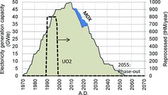
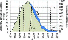
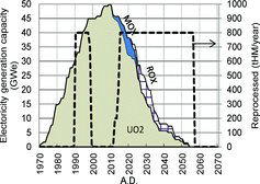
The electricity generation capacity of the “OT” scenario is shown in . The peak of 50 GWe was observed in 2010 and then decreased due to closure after 40 yr of operation on account of the Fukushima accident. All LWRs will be shut down in 2055. The Rokkasho plant will not be operated as also shown in , but 7100 tHM of SF has been reprocessed mainly in oversea facilities. The year of the reprocessing is not clear and assumed to be in the 1990s. Small amount of MOX fuel will be utilized in LWRs.
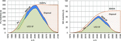
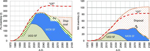
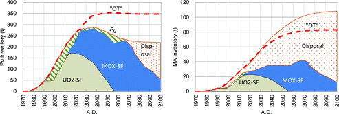
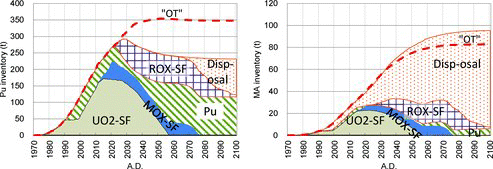
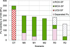
Pu inventory in the “OT” scenario is shown in , in which the main part of Pu is in UO2 SF. “Pu” in the figure is not “separated” Pu, but Pu in MOX fresh fuel in this scenario. The total amount of Pu is 350 t which is gradually disposed of to a repository from 2043 until 2105. The trend of MA inventory is almost the same, but it continues to increase after 2040 because 241Pu becomes 241Am with a half-life of 14.35 yr.
4.2. MOX scenario
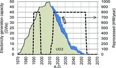
In MOX scenarios, the Rokkasho RPP, and also an MOX fabrication plant, is operated, as shown in . The total amount of UO2 SF reprocessed in the Rokkasho reprocessing plant is 33,900 tHM which is slightly higher than a planned amount of 32,000 tHM. So, the present analysis assumes an extension of the Rokkasho reprocessing plant by several years.
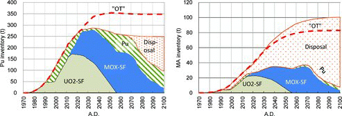
As shown in , about 75 t of Pu is separated but not burned in LWRs in the “M0” scenario. This surplus Pu is obtained from reprocessing in 2040 to 2055 when LWRs of only 8 GWe is available for MOX loading. The total amount of Pu decreases to 250 t from 350 t of the “OT” scenario, while that of MA increases by 20 t. This increment is owing to transmutation of Pu in MOX fuel to higher isotopes.
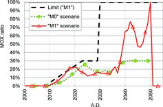
MOX loading to the LWR is limited to be less than 30% of electricity capacity in the “M0” scenario, while there is no limit for the Ohma full-MOX reactor. To decrease the surplus Pu, this limit is removed after 2030 in the “M1” scenario. As shown in , MOX loading becomes more than 30% after 2039, although the limit is removed in 2030. By this time it is too late to decrease Pu because LWRs are too few in number. As shown in , there is still surplus Pu of 40 t.
Instead of removing the limit of 30% loading, a full-MOX reactor with an electricity capacity of 1.38GWe is launched in 2030, adding to the Ohma full-MOX reactor in the “M2” scenario. The limit of 30% loading is taken for other LWRs. The added reactor will be closed in 2070, as shown in . All of the MOX fuel will be burned and transformed to the MOX SF and the amount of Pu decreases to 220 t, as shown in . The Ohma full-MOX reactor has to be operated for 45 yr beyond a 40-yr limit to irradiate all Pu.
4.3. ROX scenario
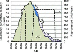
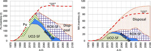
In ROX scenarios, ROX loading takes the place of MOX loading in 2020 with a limit of 30% loading, as shown in . The Ohma full-MOX reactor is regarded as a usual UO2 reactor. Surplus Pu of the “R0” scenario reaches 115 t which is larger than that of the “M0” scenario, as shown in , because the Ohma reactor is not used as a Pu burner. The amount of MA increases by 15 t as well as those in MOX scenarios.
To burn the surplus Pu, two full-ROX BWRs with 1.38 GWe electricity capacity are introduced in 2030 and 2040 each in the “R2” scenario, as shown in . The first full-ROX reactor will be operated for 40 yr, but the second one will be operated only for 24 yr because all of surplus Pu is irradiated at that time, as shown in . By utilizing the two reactors, all Pu is in ROX SF at the end, and the amount of Pu reduces to 160 t.
4.4. Pu inventory and isotopic vector
By introducing the MOX or ROX technology, the final Pu inventory can be reduced, as shown in . The referential inventory of the “OT” scenario is 350 t which is reduced to 220–250 t in “MOX” scenarios and 160–230 t in “ROX” scenarios.
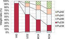
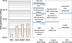
The isotopic vector of Pu is also important from the viewpoint of nonproliferation. illustrates isotopic vectors of Pu in SFs with weapon-grade Pu which consists of 239Pu of 93%. Weight ratio of 239Pu in MOX and ROX SF is 37% and 19%, respectively. A low ratio of 239Pu results in a large critical mass of a warhead. Moreover, Pu with even mass number increases, which leads to difficulty in weapon design because of high spontaneous fission neutron and heat generation. These three parameters regarding nonproliferation are tabulated in .
Table 5. Nonproliferation parameters of Pu in SF.
Based on the nonproliferation parameters above, nuclear material has been classified into few categories. Bathke has proposed a concept of the figure of merit (FOM) [Citation11] calculated from bare critical mass (BCM), heat generation, spontaneous fission neutron production and dose as given below:
(4) (high attractiveness, if 2 ⩽ FOM; medium attractiveness, if 1 ⩽ FOM < 2; low attractiveness, if 0 ⩽ FOM < 1; very low attractiveness, if FOM < 0). In the above equation, M is the BCM (kg), h is heat generation (W/kg), S is spontaneous fission neutron generation (n/s/kg) and D is dose of 0.2M evaluated at 1 m (rad/h).
The first term in the common logarithm in the right-hand side corresponds to the BCM, the second one to heat generation, the third one to spontaneous fission neutron generation and the fourth one to dose. All of these terms have a positive value and one of them is generally dominant. Equation Equation(4)(4) can be broken down to each term by assuming each of four terms is much larger than the other three terms, given as
(5) Approximately, FOM equals to the minimum value among the four FOMs in Equation Equation(5)
(5) given as
(6) If M is 800 kg, FOMBCM becomes 1, which is a boundary between low and medium attractiveness. If M is less than 80 kg, FOMBCM becomes more than 2, and the material bears high attractiveness with respect to BCM. The figure of 800 kg is taken from BCM of 20% enriched uranium and used as a measure for BCM, like 4500 W used for heat and 6.8 × 10⁶ n/s for spontaneous fission neutron production. 500 rad/h is used as a measure for dose; however, generally evaluated dose becomes much smaller than this measure and this term is negligible.
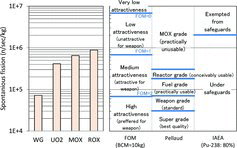
Pellaud has classified Pu using the ratio of 240Pu which is responsible for spontaneous fission neutron production [Citation12]. The classification by the 240Pu ratio was translated by authors into that by the spontaneous fission neutron rate.
Kessler has also categorized by 238Pu ratio which is dominant for heat production [Citation13]. He found that 6% of the 238Pu ratio is a boundary for denaturing Pu, which corresponds to 53 W/kg.
There is also an IAEA's guideline [Citation14] that exempts Pu with 238Pu ratio more than 80% from safeguards. The boundary can be converted into 450 W/kg of heat generation and 2.0 × 10⁶ n/s/kg of spontaneous fission neutron production.
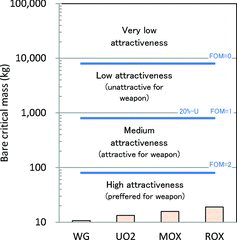
Among all the above, only FOM by Bathke can handle BCM. illustrates the BCM of Pu in each SF with boundaries of FOM. The BCM of Pu in ROX SF is the maximum by 18.9 kg which is attractive enough to be used as a weapon.
Classification based on spontaneous fission neutron production is illustrated in using the methodology of Bathke, Pellaud and IAEA. Pu in SF possesses FOMSF of around 1.0 which means medium to low attractiveness. Only Pu in ROX SF is in the low-attractiveness category. Based on Pellaud's classification, all Pu in SFs is categorized in the MOX grade which is practically unusable. Pu in UO2 SF is not of the reactor grade but in the MOX grade because 45 GWd/tHM is rather high burn-up compared to Pellaud's assumption, 33 GWd/tHM. All Pu in SFs cannot be exempted from safeguards according to IAEA's guideline.
As for classification based on heat generation by Bathke, Kessler and IAEA, all of Pu in SFs is attractive to be used as a weapon, as shown in . However, Pu in ROX SF approaches to the denatured material defined by Kessler.
4.5. Repository footprint
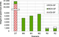
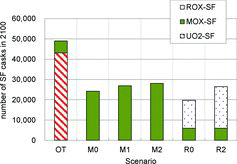
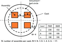
Repository footprint in each scenario was calculated considering a temperature limit in a repository, as described in Section 3.3 and appendices. The weight amount of SFs in each scenario is shown in in which the amount of UO2 SF is much larger than others. However, because MOX and ROX SFs generate large heat, the number of SF casks increases, as shown in . The average number of casks per tHM is 1.2, 5 and 40 for UO2, MOX and ROX SFs, respectively. As described in Appendix A, the number of SFs that can be contained in a cask is two to four for PWR UO2 SF, and 8–12 for BWR UO2 SF, after 50 yr of cooling, but in the case of MOX or ROX SF, the buffer temperature can exceed a limit of 90°C even if only one assembly is contained. In such cases, an assembly will be divided into a half or quarter, which leads to the large number of casks. In addition to the SF casks, there are 5600 glass waste forms in the “OT” scenario and around 37,000 forms in other scenarios.
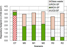
shows the contribution of each waste form to the total repository footprint in 2100. In the “OT” scenario, the UO2 SF occupies 83% of repository and a footprint of around 4 km2. After introduction of MOX or ROX, footprints are reduced to around 3.5 km2, about a half of which is occupied by MOX or ROX SF.
4.6. Potential radiotoxicity
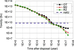
Potential radiotoxicity is often cited as an index of environmental impact of a repository in spite of its hypothetical meaning, that is, dose, when all radioisotopes are ingested by residents. The potential radiotoxicity is compared with that of natural uranium that was necessary to generate electricity resulting in the waste. The potential radiotoxicity is reduced by very little at around 10,000 yr by introducing MOX and ROX owing to transmutation of Pu, as shown in .
5. Discussion
5.1. Pu amount and nonproliferation parameters
The main purpose of transmuting Pu by the MOX and ROX technology is to eliminate residual Pu in UO2 SF. To achieve the purpose, full-MOX or full-ROX reactors must be constructed in the future, as shown in the “M2” and “R2” scenarios. Otherwise, Pu of 40–120 t remains after closing all NPPs, which leads to a nonproliferation concern. Pu amount can be reduced from 350 t in the “OT” scenario to 220 t in the “M2” scenario and 160 t in the “R2” scenario, as illustrated in ; however, the more significant effect by MOX and ROX is deterioration of Pu as a weapon.
In Section 4.4., three parameters related to nonproliferation were estimated. The first one, BCM, is increased by the ROX to 18.9 kg, as shown in . This value is still small enough for a weapon according to Bathke's FOM. However, because the ratio of 241Pu with a short half-life (14.35 yr) is larger than that of 239Pu with a long one (24,100 yr) in ROX SF, as shown in , the criticality of a warhead will decrease during storage, and such Pu can be difficult to be used as a weapon. Increment of the spontaneous fission source of Pu in MOX and ROX SF is most significant among the three parameters. FOMSF of ROX SF is less than 1, which means Pu is unattractive for being a weapon, although it is still under the safeguards. Heat generation is also increased by MOX and ROX, but the effect on nonproliferation is moderate.
As a summary of the nonproliferation issue, introduction of MOX and ROX can contribute to the safeguards, although Pu cannot be exempted. However, it should be noted that it is difficult to dissolve ROX in nitric acid and to retrieve Pu from its SF [Citation15].
5.2. Waste and repository
The main waste form of the “OT” scenario is casks containing UO2 SF. The repository footprint of this waste is about 3.2 km2. By reprocessing UO2 SF, about 32,000 glass waste forms are generated in addition to 5600 glass waste forms from oversea reprocessing. A footprint for the glass waste forms is about 1.6 km2 which is about half of the UO2 SF; however, casks containing MOX and ROX SFs occupy around 1.7 km2 which is comparable to the glass waste forms. Therefore, reduction of a repository footprint by MOX and ROX is limited due to high heat generation of these SFs. In the present scenarios, the pre-disposal storage period is fixed to be 50 yr. If this period is prolonged for MOX and ROX SFs to 100 or 200 yr, the footprint is reduced by a factor of 0.9 or 0.75. The reduction is modest because the temperature restriction is not eased due to the long half-life of the dominant heat generator, 241Am (T1/2 = 432.2 yr).
Potential radiotoxicity which is ingestion dose of waste is not reduced much by MOX and ROX. To decrease the toxicity, multiple transmutation by reprocessing MOX and ROX SFs is necessary based on the fast reactor technology.
5.3. Comparison of MOX and ROX
Both MOX and ROX technologies can burn Pu in UO2 SF if two full-MOX or two full-ROX reactors are constructed. Because performance to burn Pu of the ROX reactor is higher than the MOX one, one of the two full-ROX reactors is needed to be operated for only 24 yr, while one of the two full-MOX reactors for 45 yr. With regard to reduction of Pu inventory, ROX is preferred to MOX, because the inventory is reduced from 350 t to 160 t by ROX and to 220 t by MOX.
More significant advantage of the ROX reactor is that the ratio of 239Pu in ROX SF becomes about 20% of all Pu, which is about one-half of that in MOX SF, as shown in . As a result, Pu in ROX is less attractive for being used as a weapon with respect to spontaneous fission neutron production, as shown in . Moreover, the reprocessing of ROX SF is more difficult than that of MOX SF, owing to its insolubility to nitric acid.
As for the repository footprint and potential radiotoxicity, there is no important difference between the two. However, ROX fuel is expected to be chemically more robust underground [Citation16]. The solubility of matrix material, ZrO2, is smaller than that of SiO2 and Al2O3 by several orders of magnitude in the whole pH range. A natural analog may also support a choice of ROX, as discussed in Ref. [Citation17].
About technological readiness, the MOX technology is already available in LWRs, while the ROX one is not yet commercialized. However, most of the ROX technology is common to the UO2 and MOX one. The fabrication process of the ROX pellet is mixing of raw particles of MOX and yttria-stabilized zirconia, and sintering them similarly to that of the MOX one. An assembly design is also similar to the conventional one. Therefore, construction of a new fabrication facility dedicated to ROX fuel is not necessary; existing facility for MOX fuel can be used after slight modification. As for irradiation behavior, an irradiation test of ROX pins has been finished without any remarkable trouble [Citation18], and the next step will be test irradiation of ROX assemblies in a commercial reactor. ROX loading to LWRs can gradually increase for a next decade in the earliest case. The disposal technology for the SF canister of ROX is also similar to the conventional one, because the outside geometry of the canister is equal or smaller than that of UO2 or MOX. This is because the number of SF assemblies contained in a canister is less due to high heat production. On the whole, the technological readiness of ROX is not as high as that of MOX, but the present technologies such as UO2 LWRs, UO2 reprocessing and MOX fabrication are available as base technologies.
6. Conclusion
In order to transmute Pu in UO2 SF, ROX fuel has been developed. ROX fuel contains mainly Pu with less amount of 238U to reduce Pu production and is able to transmute most of fissile Pu. Moreover, ROX SF is chemically stable as to confine radionuclides in repository and it is difficult to obtain Pu by reprocessing.
In the present material-flow analysis, three strategies, once-through of UO2, MOX transmutation and ROX transmutation, are investigated by the NMB code developed by authors, in terms of necessary loading of MOX or ROX fuel, Pu and MA inventory, proliferation attractiveness and repository footprint. The NMB code can calculate composition change during burn-up and cooling with an error less than 10% compared to the ORIGEN code, flexibly treat many kinds of reactors, and estimate repository footprints taking into account the temperature limit.
Based on a phase-out scenario of Japan in which all commercial LWRs will be gradually closed by 2055, the analysis reveals that 350 t of Pu will be produced in UO2 SF. To achieve whole irradiation of Pu as MOX fuel or ROX fuel, two full MOX or ROX reactors are necessary in addition to 30% loading to other conventional LWRs. Because performance to burn Pu of the ROX reactor is higher than the MOX one, one of the two full-ROX reactors is needed to be operated for only 24 yr, while one of the two full-MOX reactors for 45 yr. After the irradiation, the amount of Pu is, respectively, reduced to 220 t and 160 t by MOX and ROX. Moreover, the remaining Pu in MOX and ROX SFs is considerably deteriorated to be used as a nuclear weapon, especially with respect to spontaneous fission neutron production. ROX SF is less attractive to be used as a weapon and it is more difficult to retrieve Pu by dissolving the SF than by dissolving MOX SF.
As for repository footprint, reprocessing of UO2 SF does not contribute to decreasing it, because footprints for MOX and ROX SFs are as large as that for glass waste from reprocessing. If a pre-disposal period assumed to be 50 yr in this analysis is prolonged for MOX and ROX SFs, the reduction can be enhanced, but the reduction is less than 25% by 200-yr storage. Potential toxicity which is ingestion dose of waste is not reduced much by MOX and ROX. To decrease the toxicity, multiple transmutation by reprocessing MOX and ROX SFs is necessary based on the fast reactor technology.
ROX fuel is concluded to be useful in reduction of the Pu amount and attractiveness of being used as a weapon, but it requires construction of two full-ROX reactors based on the present technologies and further research and development.
References
- Nishihara K, Tsujimoto K, Oigawa H. Scenario study for closing nuclear power generation. Paper presented at: Actinide and Fission Product Partitioning & Transmutation. Twelfth Information Exchange Meeting; 2012 Sep 24–27; Prague, Czech Republic.
- Yamashita T, Kuramoto K, Akie H, Nakano Y, Nitani N, Nakamura T, Kusagaya K, Ohmichi T. Rock-like oxide fuels and their burning in LWRs. J Nucl Sci Technol. 2002;39:865–871.
- Akie H, Sugo Y, Okawa R. Core burnup calculation and accidents analyses of a pressurized water reactor partially loaded with rock-like oxide fuel. J Nucl Mater. 2003;319:166–172.
- Akie H, Takano H, Anoda Y. Core design study on rock-like oxide fuel light water reactor and improvements of core characteristics. J Nucl Mater. 1999;274:139–145.
- Croff AG. ORIGEN-2: A revised and updated version of Oak Ridge Isotope Generation and Development code, ORNL-5621. Oak Ridge (TN): Oak Ridge National Laboratory; 1980.
- Nishihara K, Oigawa H, Nakayama S, Ono K, Shiotani H. Impact of partitioning and transmutation on the high level waste disposal for the fast breeder reactor fuel cycle. J Nucl Sci Technol. 2010;47:1101–1117.
- Suyama K, Katakura J, Ohkouchi Y, Ishikawa M. Libraries based on JENDL-3.2 for ORIGEN2 Code: ORLIBJ32ORI_J32, JAERI-Data/Code 99-003. Ibaraki (Japan): Japan Atomic Energy Research Institute; 1999 [in Japanese].
- Okumura K, Kugo T, Kaneko K, Tsuchihashi K. SRAC2006: a comprehensive neutronics calculation code system (JAEA-Data/Code 2007-004. Tokyo: Japan Atomic Energy Agency; 2007.
- Geological Isolation Research and Development Directorate. H12: project to establish the scientific and technical basis for HLW disposal in Japan, supporting report 2: repository design and engineering technology (JNC TN 1410, 2000-003). Tokyo: Japan Atomic Energy Agency; 2000.
- Japan Atomic Energy Commission. Report on comparison of nuclear fuel cycle cost in the basic scenario [in Japanese]. Tokyo: Atomic Energy Commission; 2004. Available from: http://www.aec.go.jp/jicst/NC/iinkai/teirei/siryo2004/kettei/sakutei041124.pdf
- Bathke CG, Ebbinghaus BB, Sleaford BW, Collins BA, Hase KR, Robel M, Wallace RK, Bradley KS, Ireland JR, Jarvinen GD, Johnson MW, Prichard AW, Smith BW. The attractiveness of materials in advanced nuclear fuel cycles for various proliferation and theft scenarios. Paper presented at: Global 2009; 2009 Sep 6–11; Paris, France.
- Pellaud B. Proliferation aspects of plutonium recycling. J Nucl Mater Manage. 2002;31:30–38.
- Kessler G. Plutonium denaturing by 238Pu. Nucl Sci Eng. 2007;155:55–73.
- International Atomic Energy Agency. The structure and content of agreements between the agency and states required in connection with the Treaty on the Non-proliferation of Nuclear Weapons (INFCIRC/153, IAEA). Vienna: IAEA; 1972.
- Degueldre C, Kasemeyer U, Botta F, Ledergerber G. Plutonium incineration in LWRs by a once through cycle with a rock-like fuel. Mat Res Soc Proc. 1996;412:15–23.
- Pouchon MA, Curti E, Degueldre C, Tobler L. The influence of carbonate complexes on the solubility of zirconia: new experimental data. Prog Nucl Energy. 2001;38:443–446.
- Beyerlein SW, Claiborne HC. The possibility of multiple temperature maxima in geologic repositories for spent fuel from nuclear reactors. Paper presented at: CONF-801102-40, ASME Winter Annual Meeting; 1980 Nov 16; Chicago IL.
- Klaassen FC, Schram RPC, Bakker K, Neeft EAC, Conrad R, Konings RJM. Spinel inert matrix fuel testing at the HFR petten. Paper presented at: Actinide and Fission Product Partitioning & Transmutation Seventh Information Exchange Meeting; 2002 Oct 14–16; Jeju, Republic of Korea.
Appendix A. Procedure to determine the number of SF assemblies per cask
In the NMB code, SF assemblies with various heat generation capacities are produced. To cope with direct disposal of such SF assemblies, a model based on a detailed design of UO2 SF disposal [Citation10] was employed in the code. As shown in , several SF assemblies are contained in a disposal cask made of steel. The typical number of assemblies per cask, N, is 2–4 for PWR UO2 SF and 8–12 for BWR UO2 SF after 50-yr cooling. This number is restricted by a temperature limit of buffer, 90°C. For MOX or ROX SFs, the buffer temperature exceeds this limit even if only one assembly is contained, i.e. N = 1. There are two solutions to satisfy the limit: extending the cooling period and dividing the assembly into two halves or four quarters, i.e. N = 1/2 or 1/4. The second solution is selected in the present analysis by fixing the cooling period to 50 yr, because the time required for decay is as long as several hundreds of years for PWR SF.
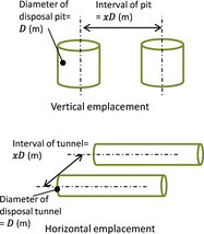
Two types of emplacement layout in repository are considered, as shown in : vertical and horizontal. In the vertical emplacement, the variable is the interval of pits which involves a cask each. In the horizontal emplacement, the variable is the interval of tunnel which involves many casks. Both variables are represented by x, i.e. the number of times of the diameter of the pit or the tunnel. The stability of rock constrains x to be larger than xmin, as listed in .
Table A.1. Minimum value of x (= xmin).
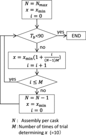
As described above, there are two variables, N and x, in this model, and the problem is to minimize the repository footprint by changing these two variables under a restriction of the buffer temperature, Tb < 90°C. For this purpose, the iteration starts at the maximum N and the minimum x, and end when Tb < 90°C, as shown in .
Appendix B. Temperature calculation of the repository
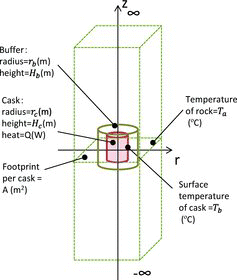
The temperature evolution of rock around the waste can be analytically obtained if the repository spreads horizontally infinitely, rock continues axially infinitely and thermal properties are independent of the temperature. The model is shown in .
The total heat source of the waste is expressed as
(B.1) where t is the time after disposal (s), Qi is the heat of nuclide i at disposal (W) and λi is the decay constant of nuclide i (/s).
The solution of the equation for thermal conduction in the rock is [Citation17]
(B.2) where T0 is the initial temperature(°C), κ is the thermal conductivity of rock (W/m/K), σ is the specific heat capacity of rock (J/kg/K), ρ is the weight density of rock (kg/m3) and erfi is the imaginary error function.
The temperature peak of the buffer occurs at the axial center of the boundary between the cask and the buffer. The temperature difference between the outside and inside surfaces of the buffer is obtained assuming a cylinder with infinite height as
(B.3) where κb is the thermal conductivity of buffer (W/m/K) andα is the correction coefficient for the axial surface (= 1.05) which is introduced to correct the heat transfer from the top and bottom surfaces.
The solution was validated by comparison with Ref. [Citation10], as summarized in . The maximum difference is 4°C which is accurate enough for the rough estimation of the NMB code. This difference is in the case that the temperature peak occurs at several years after disposal and the temperature gap between the outside and inside of the buffer is large.
Table B.1. Comparison of the maximum buffer temperature to the reference [Citation10] (PWR 45GWd/tHM, 54-yr cooling).

