Abstract
In the operation of the sodium-cooled fast reactor, the accident caused by the leakage and combustion of liquid sodium is common and frequent in sodium-related facilities. This paper is based on an experimental study of sodium fire in a columnar flow, which was carried out to focus on the burning characteristics by analyzing the temperature fields in the burner. The injection of 200 °C liquid sodium with the flux of 0.5 m3/h was poured into a 7.9 m3 volume stainless steel cylindrical burner to shape a sodium fire, and the data of temperature fields in the burner have been collected by dozens of thermocouples which are laid in the combustion space and sodium collection plate. These results show that the sodium fire in a columnar flow is composed of the foregoing centered columnar fire, the subsequent spray fire caused by atomization and the pool fire on the collection plate. The temperature close to the burning sodium flow maximally reaches up to 950 °C. The radial temperatures apart from the sodium flow are relatively low and generally about 200 °C, and maximally just 300 °C even when close to the sodium collection plate. The maximum temperature of the burning sodium dropping on the collection plate rises in the center of plate, about 528 °C. This study is helpful to evaluate the combustion characteristics, formation process and composing forms of the sodium fire in the sodium-related facilities.
1. Introduction
Liquid sodium is commonly used as a coolant in liquid metal fast reactors (LMFRs) for its better heat transfer characteristics. However, the particular disadvantage of liquid sodium is its high chemical reactivity in contact with the atmosphere, creating a potential fire hazard. A significant portion of the oxides of sodium combustion could be in the form of aerosols posing a health hazard to the exposed personnel, and the high temperature may also cause the structural damage to concrete buildings. Because accident caused by the leakage and combustion of liquid sodium is common and frequent in sodium-related facilities, one of the design basis accidents of the LMFRs is the sodium leakage from the heat transport system and sodium fire on the floor of compartments in the building. Therefore, an extensive study of sodium fire has been actively carried out in France, Japan, Russia, etc. [Citation1]. There have been a number of experimental and numerical studies on combustion behavior of liquid sodium by Hilliard et al. [Citation2], Newman [Citation3], Yamaguchi et al. [Citation4] and Takata et al. [Citation5], in which many aspects of the combustion for a stagnant pool (such as pool fire, temperature rise, burning rate and aerosol release rate) have been investigated, but the dynamics of spreading and pool formation of sodium have not been considered. The spreading of burning liquid sodium has been investigated by Subramani et al. [Citation6] using a depth-averaged shallow water equation for isothermal and non-isothermal conditions.
The spray flux of sodium is usually regarded as the most important factor affecting the consequences of sodium fire. Recently, it is commonly regarded that the sodium fire in a columnar flow would be more likely to rise than the spray fire during the real accident of sodium leak under a low pressure which would happen in the pipeline covered with the thermal insulation material [Citation1,Citation7]. Bae et al. [Citation8] reported that the characteristics of the columnar fires were almost similar to those of spray fires in an injection mass of 0.12–0.3 kg, and the maximum temperature of the test chamber was much lower even for a large amount of sodium injection, but the combustion characteristics were still not discussed in detail. Du et al. [Citation9] reported that the spray sodium burned mainly in the form of columnar sodium fire by carrying out an experimental research on the sodium spray fire in a sodium flux of 0.158 kg/s. It is necessary to have a thorough knowledge of spreading and burning characteristics of liquid sodium in a columnar flow in order to gain an accurate assessment of risks and hazards in the actual LMFRs accident.
In order to clarify the combustion characteristics, composing forms of the sodium fire in a columnar flow and the detailed dynamic formation process, this paper focuses on the study of the sodium fire by carrying out an experiment of the injection of 200 °C liquid sodium with the flux of 0.5 m3/h into a 7.9 m3 volume burner to shape a sodium fire in a columnar flow. The combustion characteristics and mechanism of the sodium fire for a columnar flow are discussed by the analysis of the temperature fields of space and the sodium collection plate of the burner.
2. Experiments
2.1. Experimental apparatus
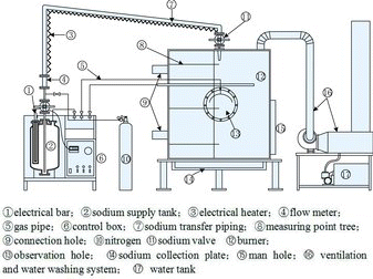
The experimental apparatus of sodium fire in a columnar flow consists mainly of the sodium supply tank, the sodium burner, the temperature acquisition system, and ventilation and water washing system as shown in .
The sodium supply tank is connected with the sodium burner by the sodium transfer piping. The top of the sodium supply tank is equipped with the sodium inlet, sodium transfer piping, electrical bar, sodium level gage, nitrogen connection, pressure gage connection for protection against overpressure control, sodium flux meter, pressure control valve and so on. The bottom of the sodium tank is equipped with the release flange for the residual sodium to release after experiments. The whole sodium supply tank is made of stainless steel via welding. The sodium tank is installed in an incubator packed with thermal insulation materials in order to reduce the thermal transmission between the tank and the external environment.
The sodium burner is a cylinder structure with a height of 2500 mm and inner diameter of 2000 mm made of stainless steel via welding. The cylinder is a double-layer structure with the interlayer packed with thermal insulation materials for an accurate detection of the experimental temperatures and safety for experimenters. The burner cylinder is equipped with a heavy gauge observation hole and manhole, the sodium nozzle on the top connected with sodium transfer piping and supply tank.
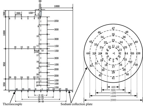
The data acquisition system consists of 28 thermocouples (T1–T28) distributed in the space, 49 thermocouples (Td1–Td49) distributed in the sodium collection plate of burner cylinder, and multi-channel temperature acquisition apparatus. The distributions of measuring points are shown in in detail. For the convenient data analysis, the thermocouples distributed in the space and sodium collection plate are distinguished, respectively, by using the marks “T” and “Td”. Twenty-eight measuring points (T1–T28) in the space located on the same vertical plane of a right angle whose horizontal plane is the sodium collection plate where the intersection of two planes is nearly a radius line of measuring points Td1–Td45. The sodium nozzle lies over the measuring point Td1 both on the centerline of the sodium burner.
The ventilation and water washing system is connected with the top of the sodium burner through a fire tube. During the experiment, the aerosols inside the burner cylinder could be discharged and cleaned through starting up the fan and water pump of the system, then it will be discharged into the large-scale vent stack.
2.2. Experimental procedure and phenomena
During the experiment, the solid metal sodium in the sodium supply tank is steadily heated up to the liquid sodium with the initial temperature of 200 °C by the electrical bar. When the sodium is heated up to approximately 100 °C, the sodium transfer piping would be heated up. In the process of heating up, the pressure of the protective nitrogen covering the liquid sodium inside the sodium tank is kept to 0.2 MPa by adjusting the pressure release valve. When the sodium valve on top of the sodium tank is opened, the sodium will be pumped out from the bottom of the sodium tank into the preheated sodium transfer piping. A sodium jet stream pours into the burner cylinder through a nozzle of 10 mm inner diameter. The sodium quantity poured into the burner is approximately 18.8 kg; the ejecting duration is around 2.5 min, and the sodium flux under the stable conditions is about 0.5 m3/hour. The sodium valve is kept open after the ejection of the liquid sodium has been completed, and then nitrogen is allowed to go in, in order to blow the residual sodium in the pipe into the burner. Three minutes later, the nitrogen and sodium valve is closed, and then the ventilation and water washing system is opened.
The sodium fire would first arise in the form of columnar fire when the liquid sodium stream met the air inside the burner. Bright flames of orange color were observed just below the nozzle while the sodium was falling to the collection plate of the burner. The sodium falling on the collection plate would continue to burn for a long time in the form of pool fire. Ten seconds after the sodium injection, the inside of the burner could not be observed due to generation of a great deal of sodium aerosol. The temperature and pressure of the sodium tank and flux of the liquid sodium were monitored when the liquid sodium was ejecting. The temperature field data of the combustion space and the sodium collection plate were gathered in real time through the temperature acquisition system, which lasted for 1.5 h.
3. Experimental data analysis
3.1. Analysis of columnar and spray fire in space
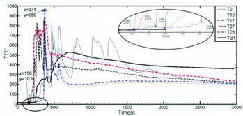
Judgment of initiating time for the sodium ejection is dependent on the temperature variation from the measuring point T2 which is just under the jet nozzle. As shown in , the temperature of T2 starts to rise at the time of 156 s first, which is confirmed as the initiating time of sodium ejection for this experiment.
The temperature distributions of representative measuring points (T10, T17, T27 and T28) are basically consistent, and the peak temperature of T17 has reached 959 °C as the highest temperature in the combustion space. The earliest temperature rise begins from T28 at the bottom close to the sodium collection plate, followed by T27, Td1, T2, T17 and T10. In the main stream area of combustion space, the temperature rise of measuring points T21 (T20, T19, T18, T17, T9) to T10 takes place almost at the same time, i.e., at about 198 s (x = 354 s) from the sodium ejection start [Citation10], which goes far beyond the duration of the sodium ejection. Therefore, the temperature rise here is triggered by the spray fire of sodium droplets splashed during the sodium flow ejection and striking the sodium collection plate, not the columnar fire. The temperature rise of the measuring point Td1 at the center of the sodium collection plate is slower and much lower than those of T28 and so on, even though there is only 150 mm space between Td1 and T28, which indicates the quick temperature rise close to the main stream center of combustion space is not triggered by the pool fire from the sodium collection plate.
The temperature distribution of the measuring point T28 in this study is similar to that of the measuring point 2 at 80 mm above the center of the sodium collection plate in the experiment of sodium spray fire conducted by the China Institute of Atomic Energy [Citation9], in which the consumption of sodium was about 25 kg, the ejecting duration was around 2 min, the sodium flow was about 0.158 kg/s and the spray pressure was 0.15 MPa, similar to the experimental conditions in this paper. It could also be found that the peak temperatures of the two measuring points are about 850 °C and both the temperatures drop slowly after about 1000 s, which agrees with the conclusion that in the spray fire experiment, there is little atomization share, and the columnar fire mainly dominates. This reflects that the experimental results of the sodium fire in a columnar flow are credible.
Therefore, at the initial phase of the liquid sodium ejection, the sodium fire burns mainly in the form of the sodium columnar fire and the temperature increases slowly, close to the sodium columnar flow. Later, the spray fire rises and lasts for a short time caused by the sodium droplets atomized during the sodium flow ejection and striking the sodium collection plate, which causes the high temperature in the main stream area of the combustion space close to the sodium columnar flow. Finally, the sodium pool fire on the sodium collection plate lasts for a long time; the highest temperature on the center of the collection plate is much lower than the high temperature in the main stream area of combustion space.
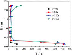
shows the temperature values at the different heights of longitudinal measuring point tree (direction: T1–T28) at a distance of 0.05 m from the sodium nozzle at the initial phase of 40, 80, 120 and 160 s during the sodium ejection. It could be clearly observed that the temperature values jump much higher at the distance close to the sodium collection plate with the time increasing, due to the accumulation, atomization and combustion of sodium striking to the plate. The temperature increases slightly at the region above 2.0 m close to the nozzle, while it rises rarely at the space of 0.5–2.0 m from the plate. The temperatures at the region of 0.5–2.0 m always remain below 50 °C before the completion of the liquid sodium ejection from the nozzle, which verifies that the space temperatures would not quickly increase in the vicinity of the columnar sodium fire in a short period of time.
Figure 4. Temperature distributions at longitudinal heights (direction: T1–T28) in the burner space.
shows the maximum temperature values (TMax) and corresponding time values (tMax T) at different heights of longitudinal measuring point tree (direction: T1–T28) at a distance of 0.05 m from the sodium nozzle during the whole experiment. The TMax values keep lower at the region close to the nozzle, only about 250 °C, while at the space below 2.0 m from the sodium collection plate, the TMax values could reach 700 °C or above. At about 1.0 m height from the plate, there exists the highest temperature zone of the entire combustion space: the TMax values are up to 950 °C despite the measuring points from the ejection center at a distance of 0.05 m, which proves that the part liquid sodium becomes atomization and burning in the vicinity of the measuring points when the columnar sodium flow dropping down during the ejection process.
Figure 5. TMax and corresponding tMax T at different longitudinal heights (direction: T1–T28) in the burner space.
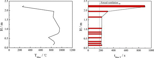
The tMax T values corresponding to the TMax values reach about 200 s at a height below about 1.5 m after the start of sodium ejection. The tMax T values are relatively long in the upper region of the burner space, especially in the vicinity of the nozzle, approximately 900 s cost. The TMax values arrived after the forced ventilation was opened in the burner.
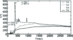
As shown in , the temperature rises in the radial direction (T21–T26) of combustion space are much less than those (such as T21) at different heights of longitudinal measuring point tree at a distance of 0.05 m from the sodium nozzle, in which the temperature rises for all the measuring points are more than 800 °C. The farthest measuring point T26 is at a distance of 1 m from the ejection center. Within such a short distance, at the same time (x = 363 s), the temperature drops sharply from 840 °C (T21), at the main stream close to the ejection center, to 120 °C (T26), at the external space. Even for the measuring point T23 at a distance of 400 mm from the center, its temperature reached only 150 °C, the peak of its temperature reached only 300 °C right at 1150 s (x = 1300 s) from the ejection start; however, at this moment, the ejection of liquid sodium has completed; therefore, the temperature rises at this moment and later, which is caused by the pool fire from the sodium collection plate. Similar temperature distributions could be observed from the other two groups of temperature data of T3–T8 and T13–T16 [Citation10], in which the general temperature rises are lower than those of T21–T26. Even for the measuring points T4 and T13 at a distance of 200 mm from the ejection center, the peaks of the temperatures reach only about 200 °C.
3.2. Analysis of pool fire
The sodium pool fire mainly has two cases: one is the large amount area, the liquid sodium covering the entire area of a certain direction (sodium collection plate) to form a uniform level of sodium; the other is the small amount area, sodium only forming a curved surface due to the surface tension not covering the entire area of a certain direction. The temperature fields formed by these two cases could be different. For the analysis of dynamic formation process of the pool fire, four temperature measuring points on each radial and Td1 point at the center are grouped and plotted as the temperature rise curve.
3.2.1. Small amount area
The radial temperature change of Td1–Td38 group in the sodium collection plate has a significant stratification, as shown in . The temperature changes of measuring points Td1, Td2 and Td14 basically have the same trend and reach a peak temperature at almost the same time. The temperature rises of measuring points T26 and T38 at the periphery are very slow, when Td1, Td2 and Td14 reach the peak of 528 °C; the temperatures of Td26 and Td38 do not reach 100 °C; after nearly 886 s (x = 1572 s in ), the temperature at Td26 rises to 300 °C, and Td38, far from the center of sodium pool, reaches the peak less than 200 °C after 40 min.
Figure 7. Temperature distributions of radial measuring points Td1–Td38 in the sodium collection plate.
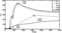
These indicate that the diffusion flow of the liquid sodium does not reach the edge of the sodium collection plate, only covering the position in the radius range of 400 mm. The temperature rises of Td26 and Td38 depend on the heat conduction coming from the sodium combustion in the radius range of 400 mm. The same temperature distribution could be observed from the four groups of temperature data of Td1–Td39, Td1–Td42, Td1–Td43 and Td1–Td44.
3.2.2. Large amount area
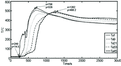
Another trend of the temperature distributions recorded by measuring points Td1–Td45 could be observed as shown in , in which the temperature rises of all measuring points in this direction remain consistent at the beginning, including the farthest one from the center of the collection plate. The peak temperatures of measuring points Td1 and Td9 rise almost at the same time, which indicates that initially the larger sodium flow quickly covers the area within a radius of 200 mm of the sodium collection plate center. Measuring points Td1 and Td9 first reached the peak temperature of 500 °C or above, and the sodium flow diffuses outward to the measuring point Td21; subsequently, the new sodium flow is no longer added into the center of the sodium pool. The diffusing sodium flows towards the edge of the collection plate relatively slowly and becomes combusting. The measuring points Td33 and Td45 of the periphery also reaches the peak temperature of about 488 °C at x = 1262 s, 556 s lagging far behind Td1, Td9 and Td21. From then, the temperatures of Td33 and Td45 are higher than the temperatures of Td1, Td9 and Td21 for a long time. Later, the temperature distributions of measuring points Td1–Td45 stabilize gradually. The same temperature characteristics could also be observed from the groups Td1–Td46 and Td1–Td40. These indicate that the liquid sodium has completely covered the direction of the collection plate, according to the order of the temperature rise, the accumulation, diffusion and combustion of sodium from the center (Td1) outwards that could be clearly observed.
3.2.3. Conflux
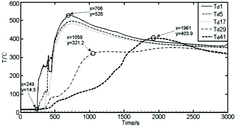
In addition, there was even a third case related to these two cases mentioned above. shows that the temperature distributions of measuring points Td1–Td41 are all along the same as the temperature trends of groups Td1–Td38, as shown in , within a radius of 200 and 400 mm of the sodium collection plate center. While within a radius of 600 and 800 mm, the temperature distributions of measuring points Td29 and Td41 are initially similar; after 1200 s, the temperature at Td41 rises quickly and reaches a peak temperature of 403.9 °C higher than other measuring points; however, the temperature at Td29 rises slowly compared to the temperature rise of Td26 in and Td33 in . These indicate that the liquid flow has covered the area within a radius of 400 mm, but not reached within a radius of 600 mm of the plate center in this measuring direction. The quick temperature rise at Td41 depends on the combustion of sodium flow coming from the circumferential direction of Td40 position, in which the sodium flow has completely covered the adjacent radius direction of Td1–Td40 and then diffused towards two sides of the plate edge (such as Td41 position).
Figure 9. Temperature distributions of radial measuring points Td1–Td41 in the sodium collection plate.
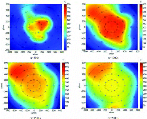
In order to study the dynamic formation process of pool fire, shows the dynamic temperature field of pool fire at x = 500, 1000, 1500 and 2000 s based on the Delaunay triangulation of experimental data, in which the temperature distribution characteristics for the cases of small amount area (Td1–Td38), large amount area (Td1–Td45) and conflux (Td1–Td41) of the pool fire discussed above could be shown visually.
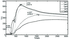
The average temperature distributions of all measuring points on the different radiuses of the sodium collection plate have a clear stratification, in which the average temperatures (e.g., TdA2 is defined as the average temperature of all measuring points on the radius of 200 mm) from the center point (TdA1) to the edge of the plate have a gradual depressed trend, as shown in . The average temperature distributions of measuring points basically have the same trend and a peak at almost the same time within a radius of 200 mm (TdA2) and 400 mm (TdA3) of the collection plate center. The average temperature changes of measuring points at the periphery within a radius of 600 mm (TdA4) and 800 mm (TdA5) are very slow and well proportioned without fluctuating, even though there are different temperature distribution characteristics depending on sodium flow combustions on the different radius directions discussed above. These indicate that even though the liquid sodium falling down on the center could diffuse randomly towards different radiuses, some reaching the edge of the sodium collection plate and some only covering the position in the radius range of 400 mm, and still diffusing to other radiuses from the initial direction, the average temperature distributions of the sodium collection plate generally keep a gradual depressed trend from the center to the edge of the plate and a relatively stable difference on different radiuses depending on the amount of combustion sodium and heat conduction in the stainless steel plate.
4. Conclusion
A sodium fire experiment in a 0.5 m3/h columnar flow with 200 °C sprayed into a 7.9 m3 volume stainless steel burner was carried out to focus on the combustion characteristics. The conclusions are summarized as follows:
The sodium fire in a columnar flow is composed of the foregoing centered columnar fire, subsequent spray fire caused by atomization of columnar flow and striking the plate and pool fire on the collection plate. The temperature close to the ejection center of sodium maximally reaches up to 950 °C; however, the radial temperature apart from the sodium flow was relatively low, maximally just 200–300 °C and the maximum temperature of the burning sodium dropping on the collection plate rises in the center of plate, about 528 °C.
As one type of the sodium fires, the spray fire generated by the foregoing columnar sodium flow and fire could not be ignored, the temperatures in the mainstream area reach 800–900 °C. Spray fire is evaluated as the most dangerous fire since the increase of space temperature is found to be the highest among the columnar fire, spray fire and pool fire even though the columnar sodium flow is injected into the burner at a low pressure.
The liquid sodium falling on the center of the sodium collection plate could diffuse randomly towards different radiuses, some only covering the position less than the radius, some reaching the edge of plate, and still diffusing other radiuses from the initial direction, the average temperatures on different radiuses of the plate generally keep a gradual depressed trend from the center to the edge and a relatively stable difference depending on the amount of combustion sodium and heat conduction in the stainless steel plate. The study is helpful to evaluate the combustion characteristics, formation process and composing forms of sodium fire in sodium-related facilities, and promises to establish a sodium fire model.
A number of experiments including putting out the sodium fire with different experimental conditions will be carried out, and we will pay more attention to the combustion characteristics and models of different sodium fires.
Additional information
Funding
References
- Yu H. Study on sodium fire of fast reactor [dissertation]. Beijing (China): China Institute of Atomic Energy; 2000. [in Chinese].
- Hilliard RK, Mccormack JD, Postma AK. Aerosol behavior during sodium pool fires in a large vessel – CSTF tests AB1 and AB2. Report no. HEDL-TME 79-28 UC-79. Hanford (WA): Hanford Engineering Development Laboratory; 1979. p. 79.
- Newman RN. The ignition and burning behavior of sodium metal in air. Prog Nucl Energy. 1983;12: 119–147.
- Yamaguchi A, Tajima Y. Numerical investigation of mass and heat transfer in sodium pool combustion. Numer Heat Transfer. 2002;A41:697–709.
- Takata T, Yamaguchi A, Maekawa I. Numerical investigation of multidimensional characteristics in sodium combustion. Nucl Eng Des. 2003;220:37–50.
- Subramani A, Jayanti S, Shet USP, Selvaraj P. Dynamics of liquid sodium pool spreading under sodium fire conditions. Nucl Eng Des. 2009;239:1354–1361.
- Uchiyama N, Takai T, Nishimura M, Miyahara S, Miyake O, Tanabe H. Investigation for the sodium leak Monju-sodium fire test-II. JNC-TN9400, 2000-090; 2000.
- Bae JH, Ahn DH, Kim YC, Cho M. An experimental study on the characteristics of sodium fires. J Korean Nucl Soc. 1994;26:471–483.
- Du HO, Wang RD, Hu WJ. The experimental research on the sodium spray fire. At Energy Sci Technol. 2011;31:41–47. [in Chinese].
- Peng KW, Zhang ZG, Guo M, Wang C, Sun SB. Experimental study on sodium column fire of sodium-cooled fast reactor. Proc. ICONE21-16089; 2013 July 28–Aug 2; Chengdu, China. [CD-ROM].

