Abstract
In nuclear engineering fields, gas–liquid bubbly flows exist in channels with various shape and size cross-sections. Although many experiments have been carried out especially in circular pipes, those in a noncircular duct are very limited. To contribute to the development of gas–liquid bubbly flow model for a noncircular duct, detail measurements for the air–water bubbly flow in a square duct (side length: 0.136 m) were carried out by an X-type hot-film anemometry and a multi-sensor optical probe. Local flow parameters of the void fraction, bubble diameter, bubble frequency, axial liquid velocity and turbulent kinetic energy were measured in 11 two-phase flow conditions. These flow conditions covered bubbly flow with the area-averaged void fraction ranging from 0.069 to 0.172. A pronounced corner peak of the void fraction was observed in a quarter square area of a measuring cross-section. Due to a high bubble concentration in the corner, the maximum values of both axial liquid velocity and turbulent kinetic energy intensity were located in the corner region. It was pointed out that an effect of the corner on accumulating bubble in the corner region changed the distributions of axial liquid velocity and turbulent kinetic energy intensity significantly.
1. Introduction
Gas–liquid bubbly flows play a significant role in a light water nuclear reactor. Therefore, many studies regarding the gas–liquid bubbly flows have been conducted so far in order to develop the two-phase hydraulic model for providing a reliable hydraulic design and increasing the safety assurance.
As for upward gas–liquid bubbly flows in small circular pipes with the inner diameter less than 60 mm, Serizawa et al. [Citation1,2], Wang et al. [Citation3] and Liu & Bankoff [Citation4,5] have measured several local flow parameters, such as the void fraction, bubble frequency and so on, of gas phase by means of an electric conductivity probe, and the liquid velocity and turbulent characteristics of liquid phase by a hot-film anemometry. Several typical features of the flows were reported, such as (1) a pronounced wall peak of the void fraction existed in the low area-averaged void fraction flow condition and (2) a high bubble concentration near the wall caused the increase of axial liquid velocity and turbulent intensity there. These experimental databases shed important light on the gas–liquid bubbly flow modeling. Several gas–liquid bubbly flow models in circular pipes were established [Citation6–8] based on the databases in circular pipes.
In addition to the gas–liquid bubbly flows in circular pipes, those in channels with various shape and size cross-sections are also often encountered in nuclear fields. Here, taking the maximum stable bubble size into consideration, the cross-section with the hydraulic diameter over 0.1 m is categorized to a large flow channel in the atmospheric conditions [Citation9]. For example, in order to provide the driving head in the natural circulation boiling water reactor, the chimney above the reactor core is partitioned into several large square flow channels. The gas–liquid two-phase flows with various flow patterns such as the low void fraction bubbly flow and the high void fraction churn and annular flows exist in these square flow channels depending on the operation conditions in the reactor. However, there is no guarantee that the two-phase flow model based on circular pipe flows could be applied to such a large noncircular flow channel. It is well known that the single-phase turbulent flow in a noncircular duct shows anisotropic turbulent feature which causes the existence of a transverse flow in the cross-section plane, termed “the secondary flow of the second kind” [Citation10–13]. Therefore, the gas–liquid bubbly flow feature in a noncircular duct might be different from that in a circular pipe.
Literature surveys on existing experimental database of upward air–water bubbly flows in noncircular ducts are summarized in . In this table, experimental studies on the flows in narrow rectangular ducts with a large aspect ratio are excluded. Profiles of several local flow parameters along a bisector only in the cross-section have been measured [Citation14–19]. However, to understand geometry effect on the flow, data in a whole symmetric area including a corner which characterizes the geometry effect in a noncircular cross-section are inevitable. The void fraction distribution in a whole symmetric area was first measured by Sadatomi et al. [Citation20] in two types of a small noncircular duct. It was reported the void fraction tended to peak near walls and corners in a low area-averaged void fraction case. It was also proven by the following studies [Citation21,22]. Although database is very important for the bubbly flow modeling, in contrast with the abundant database of pipe flows, especially for liquid phase data, those in only six flow conditions are available in a small triangular duct [Citation21].
Table 1. Existing experimental databases of upward air–water bubbly flows in noncircular ducts.
In addition, as shown in , the investigators focused on the flow in small noncircular ducts although there are large noncircular channels. A scale-up effect on the flow in circular pipes has been reported [Citation23–30]. In large circular pipes, the gas–liquid bubbly flow shows the following characteristics: (1) the strong turbulence and the secondary flow induced by large cap bubbles, (2) a small wall peak of the void fraction profile. Therefore, the flow in large noncircular ducts should be investigated by taking the flow channel scale-up effect into consideration.
To contribute to the development of gas–liquid bubbly flow model for the flow channel with a large noncircular cross-section, upward air–water bubbly flow experiment was conducted in the large square duct using an X-type hot-film anemometry and a multi-sensor optical probe.
2. Experimental system
2.1. Experimental apparatus
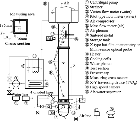
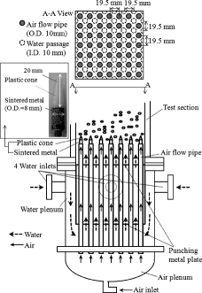
A schematic diagram of experimental apparatus is shown in . The test section was a 2.9 m long vertical smooth acrylic resin square duct with the inside cross-section of 0.136 m×0.136 m (hydraulic diameter: DH = 0.136 m). To avoid the large bubbles being significantly limited by the size of the duct, the duct was fabricated by considering the requirement that its hydraulic diameter is greater than the maximum stable bubble size (0.1 m in the atmospheric conditions). Pure water in a storage tank was circulated through the test section by a centrifugal pump. The total water flow rate was measured by a vortex liquid flow meter (±1% full scale (120 m3/hour)). After the water passing the flow meter, the flow was divided into four water supply lines and gathered into a water plenum from four water inlets perpendicular to each sidewall of the test section (see ). Four Pitot type flow meters were set to each flow line in order to control a symmetric water supply. Air was supplied by an air compressor and the total air flow rate was measured by two mass flow meters (±1% full scale (500 l/min) and 2% full scale (100 l/min), respectively) before injected to an air plenum in an air–water mixing chamber (see ). In the air–water mixing chamber, the water flow was strained by two plates of punching metal and mixed with the air in the surface of 7×7 rod bundle cylindrical sintered metals (SMC Corp.) which were fixed in the top of each air flow pipe. The sintered metal pore size is based on the nominal filtration density of 120 μm. After the upward bubbly flow passed out the test section, the air was separated in the upper tank and the water was circulated.
Although the upward gas–liquid two-phase flow is developing continuously along the flow direction due to the expansion of gas phase primarily caused by the hydrostatic pressure reduction, it can be thought generally that the flow reaches to a quasi-fully developed flow or fully developed flow when little flow parameter distribution change occurs along the flow direction and inlet influence on the flow disappears. In view of the locally measured radial distributions of void fraction in vertical large pipes of 0.102 and 0.152 m in diameter, Smith et al. found that the little flow development occurs in the two-phase flow with z/DH > 4–5 [Citation31]. Omebere-Iyari et al. experimentally concluded that the two-phase flow was fully developed at z/DH = 7.7 in a vertical large pipe with 0.194 m in diameter [Citation32]. Shen et al. reported that the two-phase flow at z/DH > 15 reached a fully developed flow in a vertical large pipe of 0.2 m in diameter [Citation26]. Therefore, in the two-phase flow with z/DH > 15, the inlet influence on the flow may disappear and the flow may be fully developed in a vertical large flow channel. To obtain the experimental data in the fully developed flow with little inlet influence, the local measurements were performed for the flow at the most downstream axial position of z/DH = 16 only in this study.
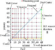
The distributions of void fraction, bubble frequency and axial liquid velocity, turbulent characteristics in a cross-section at the most downstream axial position of z/DH = 16 were measured by an X-type hot-film anemometry (Dantec Corp. 55R61, cylindrical sensor outer diameter is 70 μm and the length is 1.25 mm). The hot-film anemometry was fixed to a special designed x–y traversing device. The traversing device was controlled by a micrometer and an electrical caliper with the accuracy of 10 μm in x and y directions, respectively. In an octant triangular area (surrounded by a bisector and diagonal line) or a quarter square area of the measuring cross-section, totally 66 or 121 measuring points were adopted, i.e. the intersection points of two lines which were in the distance of 3.5, 5, 8, 12, 17, 23, 30, 38, 47, 57 and 68 mm from each wall as shown in . Measurements by the hot-film anemometry were performed in 11 two-phase flow conditions (three cases and eight cases in the octant triangular area and the quarter square area, respectively) as shown in , where all the values were at z/DH = 16. In this study, we focused on measuring local flow parameters especially for liquid phase because those databases in large noncircular ducts are very essential but limited until now. Although the hot-film anemometry is one of the most capable measuring techniques for local liquid phase parameters of the two-phase flow, it has a significant limitation in the reliable measurement of the high void fraction flow. Therefore, this study had to measure the flow characteristics of the large square duct in the low void fraction bubbly flow conditions. In addition, the measurements in the quarter square area for three single-phase flow conditions with the same superficial liquid velocity ⟨Jl⟩ were carried out.
Table 2. Hot-film anemometry measuring two-phase flow conditions in this experiment.
The temperatures of water at the inlet and outlet of the test section were measured by thermocouples. To minimize velocity drift of the hot-film anemometry calibration, the water temperature change at the inlet was controlled to within ±0.1 °C by means of a heater and cooling coils in a storage tank. The water temperature was ranged from 33.2 to 36.3 °C among all flow conditions so that the temperature influence on the flow properties could be ignored.
After the hot-film anemometry measurements, a multi-sensor optical probe, i.e. a flat-tip type probe [Citation33,34] was used to measure the bubble diameter profiles along the diagonal, x-bisector and x-wall-nearest line (see ) in the same two-phase flow conditions at z/DH = 16.1. The optical probe was traversed by the same traversing device as the hot-film anemometry. In the optical probe measurements, the water temperatures at the inlet were kept to about 34.5 ± 0.5 °C among all flow conditions.
In addition to the local measurements, the bubbly flow at the measuring station was visualized by a high speed camera (GX-P, Nac Corp.) with the frame rate of 4000 fps. Six pressure taps were set at the axial positions of z/DH = 1, 5, 10, 15, 16.5 and 19, respectively. The pressure differences in the axial direction were measured between two neighboring pressure taps of z/DH = 1, 5, 10, 15 and 19 by four differential pressure transmitters (±0.1% full scale (2.4, 2.8, 2.8 and 2.4 kPa, respectively)). The pressure difference data by a differential pressure transmitter (±0.1% full scale (2 kPa)) between z/DH = 15 and 16.5 were used to quantify the results of the void fraction measured by the hot-film anemometry as mentioned later. Two pressure gauges (±0.1% full scale (100 kPa)) were set at z/DH = 1 and 19.
2.2. X-type hot-film anemometry measurement
Hot-film anemometry has been widely used for measuring gas–liquid two-phase flows, such as the local parameters of instantaneous liquid velocity, void fraction and bubble frequency simultaneously.
In this experiment, data were acquired with the sampling time and rate of 100 s and 10 kHz, respectively. The phase discrimination algorithm for a hot-film anemometry by setting the threshold of both the signal level and the slope [Citation4] was used. The void fraction and the bubble frequency were calculated by EquationEquation (1)(1) as the ratio of gas phase duration time tg to sampling time T and defined by EquationEquation (2)
(2) as the ratio of bubble number Nb to sampling time T, respectively,
(1)
(2) Before every experiment, a velocity calibration is inevitable for a hot-film anemometry. In this experiment, relation of the axial liquid velocity measured by a Pitot tube in the duct center of the measuring cross-section and the total water flow rate was obtained in advance. Prior to each experiment, velocity calibration of the hot-film anemometry was carried out in the duct center at the measuring cross-section through changing the total water flow rate. The effective velocity of each sensor i, Ueff,i is expressed as
(3) where the yaw factor ky = 0.2 (Dantec Corp. recommendation for 55R61) was applied. In this experiment, the axial liquid velocity was in z-direction (see ). When the sensor planes and the probe axis of the X-type hot-film anemometry were parallel to the y–z plane (see ) and along with the z-direction, respectively, the conversion between the sensor's coordinate and the test section coordinate is expressed as
(4) Substituting EquationEquation (4)
(4) into EquationEquation (3)
(3) , assuming Winst ≫ Vinst, the following equations are obtained:
(5)
(6) Thus the axial liquid velocity W, the root mean square (rms) values of instantaneous local velocity fluctuation w and v in the axial and the lateral directions can be measured.
2.3. Multi-sensor optical probe measurement
The multi-sensor optical probe is very popular for measuring local characteristics of gas phase in gas–liquid two-phase flows. The data were acquired by a data acquisition system (WE7000, Yokogawa Electric Corp.) with the sampling rate and time of 10 kHz and more than 100 s, respectively. The phase discrimination algorithm for the optical probe measurement by setting a signal level threshold based on whole liquid and gas signal levels [Citation34] was used.
Since the present experiments were performed at the low void fraction flow conditions, the bubbles can be assumed to move parallel to the optical probe. The jth bubble interfacial velocity in the axial direction vg,j can accordingly be obtained by using the ratio of the distance between the front and rear sensors to the time lag when an interface of the jth bubble is penetrated by the front and rear sensors. Therefore, the jth bubble chord length χj was obtained as follows
(7) where tg,j is the duration time of the jth bubble. In this experiment, the bubble diameter Db is calculated as follows
(8) where g(χ) is the probability density function of bubble chord length [Citation35]. This method was also applied to measure the bubble diameter by Liu and Bankoff [Citation5] and Shawkat et al. [Citation25] in upward air–water bubbly flow.
3. Measurement quantification
The flow symmetry was checked in all flow conditions measured in the quarter square area based on the data comparison of the axial liquid velocity W and the void fraction α along two symmetric bisectors, where 11 pairs of the symmetric points were measured in each bisector. The flow symmetry was confirmed with the average deviation for the data of W and α between each pair of the symmetric points about 3% and 4%, respectively.
Because the velocity drift of the hot-film anemometry calibration in every experiment may occur due to the hot-film surface contamination through the measurement, the results of axial liquid velocity in the duct center before and after the experiment were compared, and the averaged difference was about 1%.
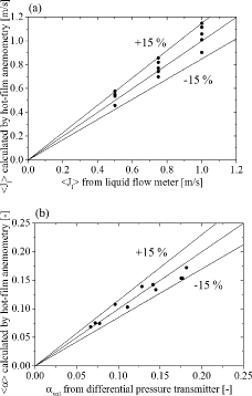
To quantify the measuring data of α and W, the area-averaged void fraction ⟨α⟩ and the superficial liquid velocity ⟨Jl⟩ obtained by the hot-film anemometry measurement were compared with the volumetric void fraction αvol by the differential pressure transmitter and ⟨Jl⟩ measured by the liquid flow meter, respectively. ⟨α⟩ and ⟨Jl⟩ by the hot-film anemometry measurement are expressed as follows:
(9)
(10) The axial pressure difference in the two-phase flow is the difference between the wall frictional pressure drop of the two-phase flow and gas hold-up related to the volumetric void fraction αvol. Since the wall frictional factor for the single-phase flow in a rectangular duct and a circular pipe are similar with the difference of about ±5% [Citation20], the wall friction of single-phase flow in the square duct was given based on a circular pipe model. After combining the measured axial pressure difference and the calculated wall frictional pressure drop of two-phase flow by Chisholm and Laird correlation [Citation36], the volumetric void fraction αvol was obtained. Both quantification results for all flow conditions were presented in . The good agreement between ⟨α⟩ and αvol was made with the maximum difference about 13%, so as to ⟨Jl⟩ with the maximum difference about 15%.
4. Results and discussion
4.1. Void fraction, bubble diameter, bubble frequency and axial liquid velocity
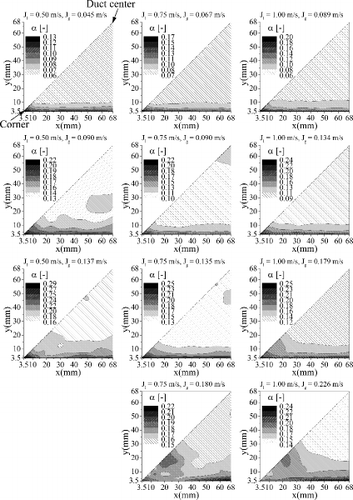
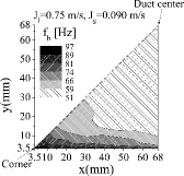
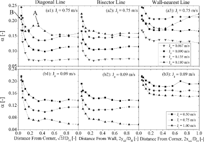
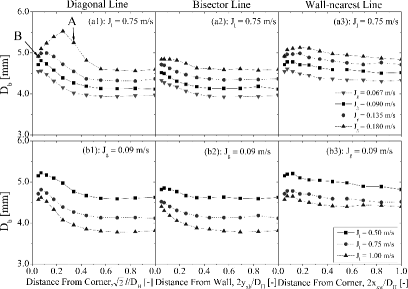
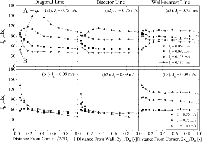
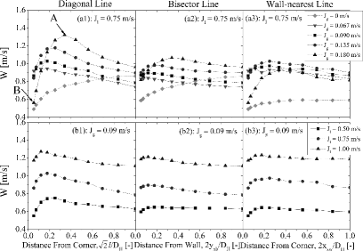
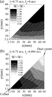
The distributions of void fraction in all flow conditions in the symmetric octant triangular area are presented in . In addition, and show the distributions of bubble frequency and normalized axial liquid velocity in a typical flow condition of ⟨Jl⟩ = 0.75 m/s and ⟨Jg⟩ = 0.090 m/s in the same triangular area; the distribution of axial liquid velocity for the single-phase flow is added for comparison in . The values of ⟨W⟩ were presented in . In order to compare the results among flow conditions, the profiles of void fraction, bubble diameter, bubble frequency and axial liquid velocity at (a) a constant ⟨Jl⟩ and (b) a constant ⟨Jg⟩ are shown in –, respectively. The figure columns from left to right categorize the profiles along the diagonal, x-bisector (i.e. x = 68 mm) and x-wall-nearest line (i.e. y = 3.5 mm) based on the relative positions of (0: corner; 1: duct center), 2yxb/DH (0: wall center; 1: duct center) and 2xxw/DH (0: corner; 1: wall center), respectively as shown in .
Figure 7. Normalized axial liquid velocity distributions ((a) ⟨Jl⟩ = 0.75 m/s and ⟨Jg⟩ = 0 m/s; (b) ⟨Jl⟩ = 0.75 m/s and ⟨Jg⟩ = 0.090 m/s).
4.1.1. Void fraction
As shown in , pronounced peaks of the void fraction were observed in the corner and wall. The distributions were almost flat outside the wall region. Except for high area-averaged void fraction flow conditions (⟨Jl⟩ = 0.75 m/s and ⟨Jg⟩ = 0.180 m/s, and ⟨Jl⟩ = 1.00 m/s and ⟨Jg⟩ = 0.226 m/s), the maximum value was in the corner.
According to the profiles along the wall-nearest line, except for the high area-averaged void fraction flow condition (⟨Jl⟩ = 0.75 m/s and ⟨Jg⟩ = 0.180 m/s), a pronounced peak in the corner region and a flat pattern outside that along the wall are shown in (a3) and 8(b3). It was suggested that an effect of the corner on accumulating bubble was significant rather than that outside the corner region along the wall. This corner peaking phenomenon of the void fraction has also been observed for upward air–water bubbly flow in small noncircular ducts (DH < 40 mm). It may be due to the following reasons: (1) The lift force is thought as one of the mechanisms to push bubbles to the wall in these flow conditions with small bubble diameter as seen in . Since the lift force is proportional to the liquid mean velocity gradient [Citation37,38], the largest velocity gradient along the diagonal in the corner region both for the single- and two-phase flows as shown in could cause the maximum value of void fraction there; (2) The bubble lateral motion in the corner region is expected to be more restricted than that outside the corner region along the wall. It was suggested that bubbles were relatively difficult to move from the corner towards the wall center and (3) The secondary flow of the second kind (a transverse flow in an octant triangular area in the single-phase flow) might also exist in the two-phase flow and entrain bubbles to the corner region.
In addition, the void fraction profiles changed with the flow condition change as shown in . Decreasing ⟨Jl⟩ at a constant ⟨Jg⟩ increased the void fraction especially in the duct center region and also decreased the gradient of void fraction. According to Tomiyama et al. [Citation39], small bubbles tended to migrate to lower liquid velocity region due to the lift force and the lift force decreased with the bubble diameter increasing. With changing these flow conditions, the bubble diameter increased monotonously as seen in so that the weaker lift force pushed bubbles to the wall.
Similarly, as increasing ⟨Jg⟩ at a constant ⟨Jl⟩, the bubble diameter also increased monotonously as shown in . When ⟨Jg⟩ becoming 0.180 m/s at ⟨Jl⟩ = 0.75 m/s, the peak value in the corner became lower than that in the wall center (see (a3)), and the second peak existed nearby (see (a1)). It is interesting to note that although bubbles tended to be accumulated in the corner rather than in the wall in the low area-averaged void fraction flow conditions, the phase distribution pattern transition first occurred from the corner with increasing ⟨Jg⟩. This could be attributed to that bubbles with larger diameter near the corner (see ) departed from the corner. According to Tomiyama et al. [Citation39], the lift force changed its direction to push bubbles to higher liquid velocity region with the bubble diameter increasing. The bubble size effect on the void fraction profile has been examined in upward air–water bubbly pipe flows [Citation40]. It was reported that the critical bubble diameter was 5–6 mm for causing the transition of void fraction peak from the wall (lower liquid velocity region) to the core (high liquid velocity region). This critical bubble diameter was coincident with that in this experiment as seen in . Moreover, Serizawa and Kataoka [Citation41] presented a phase distribution pattern map and categorized the phase distribution pattern to wall peak, intermediate peak, core peak and transition in circular pipe flows. Based on their map, this flow condition should be classified in the transition region which was mentioned as the void fraction with a pronounced peak near the wall and a broad peak in the core. However, there were two void fraction peaks existing in the corner region but none in the duct center in this experiment as shown in (a1), where two peaks are indicated as peak A and B, respectively. This phenomenon is the characteristic of the upward bubbly flow in the large square duct and will be discussed in Section 4.1.3.
4.1.2. Bubble diameter
Increasing ⟨Jg⟩ at a constant ⟨Jl⟩ and decreasing ⟨Jl⟩ at a constant ⟨Jg⟩ increased the bubble diameter in all locations as shown in . The profiles along the diagonal and the bisector show a peak in the corner region and the wall center, and relatively flat pattern in the duct center. The peak locations of the bubble diameter were almost the same to those of the void fraction (see ). The main reason could be that a higher bubble concentration caused a higher probability of bubble coalescence in the corner region and the wall center. Moreover, the bubble diameter in the corner region was larger than that in the wall center in all flow conditions because the peak value of void fraction in the corner region was higher than that in the wall center in all flow conditions except the flow condition of ⟨Jl⟩ = 0.75 m/sand ⟨Jg⟩ = 0.180 m/s (see ). As for this exceptional case, it was shown two peaks of the void fraction in the corner region. It was expected that the higher void fraction in the upstream in the corner caused a higher probability of bubble coalescence there, and eventually large bubbles departed from the corner to make the peak of the bubble diameter nearby in the measuring cross-section.
4.1.3. Bubble frequency
Similar to the distribution of void fraction, the bubble frequency had a pronounced peak in the corner and wall, and the maximum value was in the corner in a low area-averaged void fraction flow condition (⟨Jl⟩ = 0.75 m/s and ⟨Jg⟩ = 0.090 m/s) as shown in . The bubble frequency distributed as a flat pattern outside the wall region.
Due to the effect of the corner on accumulating bubble, the bubble frequency peaked in the corner region and the wall, and the peak value in the diagonal was always higher than that in the bisector in all flow conditions as shown in . As increasing ⟨Jg⟩ at a constant ⟨Jl⟩, the value of the bubble frequency in the corner decreased and its peak location moved off the corner toward the duct center (see (a1)). As for the flow conditions of ⟨Jl⟩ = 0.75 m/s and ⟨Jg⟩ = 0.135 and 0.180 m/s, the peak location of the bubble frequency was approximately coincident with that of the maximum axial liquid velocity as presented in (a1). The bubble frequency in the corner was decreased drastically even much smaller than that in the wall center in the flow condition of ⟨Jl⟩ = 0.75 m/s and ⟨Jg⟩ = 0.180 m/s (see (a1) and 10(a2)). Comparing this profile along the diagonal with the void fraction profile, the peak location A near the corner was coincident with that of the void fraction peak A; however, there was no bubble frequency peak in the corner (location B) as the void fraction peak B (see (a1) and 10(a1)). The bubble frequency is related to not only the void fraction but also the bubble diameter and the bubble interfacial velocity. From (a1), the bubble diameter decreased only about 5% from the location A to B. On the other hand, the bubble interfacial velocity was expected to decrease more taking into consideration the axial liquid velocity data with about 200% decreasing from the location A to B (see (a1)). Therefore, the discrepancy of the peaks of void fraction and bubble frequency in the corner (location B) could be due to very low bubble interfacial velocity there causing the low bubble frequency with the high void fraction.
Besides, as increasing ⟨Jl⟩ at a constant ⟨Jg⟩, the bubble frequency was not changed significantly in the duct center but increased in the corner and wall region which was consistent with the result in a small circular pipe [Citation5].
4.1.4. Axial liquid velocity
Although the axial liquid velocity had a peak in the duct center in the single-phase flow, in contrast, the maximum axial liquid velocity existed near the corner in the two-phase flow condition (⟨Jl⟩ = 0.75 m/s and ⟨Jg⟩ = 0.090 m/s) as shown in .
According to , the profiles of axial liquid velocity peaked near the corner and wall center in almost all two-phase flow conditions. This velocity wall-peaking phenomenon is caused by much higher bubble concentration in the corner and wall center indicated by the distributions of both the void fraction and the bubble frequency due to the buoyancy effect of bubbles on the axial liquid velocity. In addition, it was found that the peak value of axial liquid velocity near the corner was higher than that near the wall center in all flow conditions owing to a higher void fraction in the corner region. The velocity wall-peaking phenomenon has also been reported by Wang et al. [Citation3] for upward air–water bubbly flows in a circular pipe and termed the “chimney effect” due to a high void concentration in the wall.
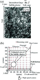
In the flow condition of small ⟨Jg⟩, the axial liquid velocity of two-phase flow was smaller than that of single-phase flow in the duct center as shown in (a1). As increasing ⟨Jg⟩ at a constant ⟨Jl⟩, the peak value was increased and the peak location was moved away from both the wall and the corner toward the duct center. Moreover, the axial liquid velocity tended to be reduced especially in the corner. When ⟨Jg⟩ reached to 0.180 m/s at a constant ⟨Jl⟩ = 0.75 m/s, the axial liquid velocity was increased significantly near the corner as shown in location A in (a1). In this flow condition, intermittent large bubble clusters formed by bubble agglomeration in the corner were observed with the frequency of about 2 Hz based on the visualization as shown in (a). Assuming the shape of bubble clusters was symmetric to the diagonal plane, the area of bubble clusters in the cross-section was estimated as shown in (b) based on the visualization and the bubble diameter profiles along the diagonal. It was shown that the axial liquid velocity peak location A in (a1) was in the estimated area of bubble clusters in (b). Because the surrounding liquid could be entrained by the wake of these bubble clusters, the axial liquid velocity was increased in addition to the buoyancy effect caused by a higher bubble concentration there. Due to the lower bubble frequency in the corner (see (a1) and 10(a3)) and the high wall friction, the axial liquid velocity in the corner was lower than that in the smaller ⟨Jg⟩ flow conditions and even close to the single-phase level. Based on the visualization, bubbles in the corner moved upwardly slower than those in the estimated area of bubble clusters, which was coincident with the expectation about the low bubble interfacial velocity in the corner resulting in the low bubble frequency with the high void fraction there.
Besides, as decreasing ⟨Jl⟩ at a constant ⟨Jg⟩, the profile of axial liquid velocity tended to be flatter. There was almost no peak in the bisector profile in the flow condition of ⟨Jl⟩ = 0.50 m/s and ⟨Jg⟩ = 0.090 m/s (see (b2)).
4.2. Turbulent kinetic energy intensity (k/⟨W⟩2)
The rms value of lateral instantaneous velocity fluctuation u is able to be calculated based on the geometrical assumption that the distributions of u and v in the quarter square area are symmetry about the diagonal. In this manner, normalized turbulent kinetic energy intensity was calculated and the distributions in the flow conditions of ⟨Jl⟩ = 0.75 m/s and ⟨Jg⟩ = 0, 0.090 and 0.180 m/s were presented in , respectively. As for the single-phase flow, the maximum turbulent kinetic energy intensity was located in the wall center and decreased toward both the duct center and the corner. After introducing bubbles, the distribution was totally changed to have a peak in the corner region due to the higher bubble concentration there. It was suggested that the effect of the corner on accumulating bubble could change the turbulent kinetic energy intensity distribution significantly.
Figure 13. Turbulent kinetic energy intensity distribution ((a) ⟨Jl⟩ = 0.75 m/s and ⟨Jg⟩ = 0 m/s; (b) ⟨Jl⟩ = 0.75 m/s and ⟨Jg⟩ = 0.090 m/s; (c) ⟨Jl⟩ = 0.75 m/s and ⟨Jg⟩ = 0.180 m/s).
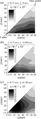
As increasing ⟨Jg⟩ at a constant ⟨Jl⟩ and decreasing ⟨Jl⟩ at a constant ⟨Jg⟩, the peak of the turbulent kinetic energy intensity moved away from the corner as shown in (a1) and 14(b1), which was coincident with the tendency of bubble frequency profile change. Due to the bubble agitation effect, the turbulent kinetic energy intensity in the two-phase flow was always higher than that in the single-phase flow and increased the value as increasing ⟨Jg⟩ at a constant ⟨Jl⟩ and decreasing ⟨Jl⟩ at a constant ⟨Jg⟩.
Figure 14. Turbulent kinetic energy intensity profiles (a) at constant ⟨Jl⟩ and (b) at constant ⟨Jg⟩.
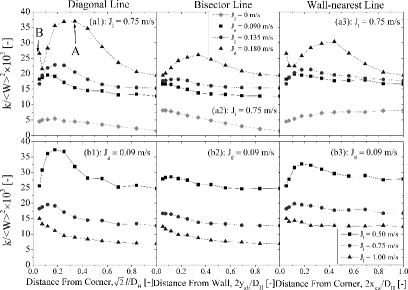
In the flow condition of ⟨Jl⟩ = 0.75 m/s and ⟨Jg⟩ = 0.180 m/s, two peaks of the turbulent kinetic energy intensity existed in the corner region, indicating as peak A and B, respectively, in (a1). The peak A was caused by the high bubble agitation effect there and the location was in the estimated area of bubble clusters and the same as that of the bubble frequency peak. As for the peak B in the corner, it was conjectured that large eddies from the intermittent large bubble clusters remained there and generated the high turbulent kinetic energy there.
5. Conclusions
To contribute to the development of gas–liquid bubbly flow model for the flow channel with a large noncircular cross-section, the detail measurement for upward air–water bubbly flow in a large square duct (DH = 0.136 m) was performed. In addition to three single-phase flow cases as the reference, 11 two-phase flow conditions with the combination of ⟨Jl⟩ in the range of 0.50–1.00 m/s and ⟨Jg⟩ in the range of 0.045–0.226 m/s, covering the area-averaged void fraction ranged 0.069–0.172, were measured. Based on the measurement database of void fraction, bubble diameter, bubble frequency, axial liquid velocity and turbulent kinetic energy, the following concluding remarks were drawn:
Pronounced peaks of the void fraction and the bubble frequency existed in the corner region due to a significant effect of the corner on accumulating bubble there.
The maximum value of the bubble diameter was in the corner region because of a higher probability of bubble coalescence resulted from the much higher bubble concentration there.
As increasing ⟨Jg⟩ at a constant ⟨Jl⟩, the phase distribution pattern transition from the corner or wall center to the duct center tended to occur from the corner because of the larger bubble diameter in the corner.
Owing to the higher bubble concentration in the corner region, the axial liquid velocity was increased and had a maximum value near the corner.
Bubble-induced turbulence strongly affected the distribution of turbulent kinetic energy intensity. Because of the higher bubble concentration in the corner region, the peak location of turbulent kinetic energy intensity changed from the wall center in the single-phase flow to the corner region in the two-phase flow.
Nomenclature
| g | = | Gravitational acceleration |
| z | = | Height from the bubble generating point in the axial direction |
| D | = | Circular pipe diameter |
| DH | = | Hydraulic diameter |
| fb | = | Bubble frequency |
| Db | = | Bubble diameter |
| tg | = | Gas phase duration time |
| T | = | Sampling time |
| Ng | = | Bubble number |
| Ueff,i | = | Effective liquid velocity of sensor i |
| UN,i | = | Instantaneous liquid velocity normal to sensor i |
| UT,i | = | Instantaneous liquid velocity tangential to sensor i |
| ky | = | Yaw factor |
| (x, y) | = | Cartesian coordinate in the cross-section |
| (Winst, Vinst) | = | Instantaneous liquid velocity in the axial and y directions |
| W | = | Time-averaged liquid velocity in the axial direction |
| (w, v, u) | = | Root mean square values of instantaneous local velocity fluctuation in the axial, y and x directions |
| uw | = | Reynolds shear stress in the axial and x directions |
| vg | = | Bubble interfacial velocity |
| Jl | = | Superficial liquid velocity |
| Jg | = | Superficial gas velocity |
| l | = | Distance from the corner to the duct center along diagonal |
| yxb | = | Distance from the wall center to the duct center along x-bisector line |
| xxw | = | Distance from the corner to the wall center along x-wall-nearest line |
| k | = | Turbulent kinetic energy |
| S | = | Measuring area |
| P | = | Pressure |
Greek letters
| α | = | Void fraction |
| αvol | = | Volumetric void fraction |
| χ | = | Bubble chord length |
Subscripts for
| 1 | = | Sensor 1 of the X-type hot-film anemometry |
| 2 | = | Sensor 2 of the X-type hot-film anemometry |
| j | = | The jth bubble |
Mathematical symbols
| ⟨⟩ | = | Cross-sectional area-averaged quantity |
Acknowledgements
The authors were grateful for “Energy Science in the Age of Global Warming” of Global Center of Excellence (G-COE) program (J-051) of the Ministry of Education, Culture, Sports, Science and Technology of Japan.
Additional information
Funding
References
- Serizawa A, Kataoka I, Michiyoshi I. Turbulence structure of air–water bubbly flow – I. Measuring techniques. Int J Multiphase Flow. 1975;2(3):221–233.
- Serizawa A, Kataoka I, Michiyoshi I. Turbulence structure of air–water bubbly flow – II. Local properties. Int J Multiphase Flow. 1975;2(3):235–246.
- Wang S, Lee S, Jones O, Lahey R. 3-D turbulence structure and phase distribution measurements in bubbly two-phase flows. Int J Multiphase Flow. 1987;13(3):327–343.
- Liu TJ, Bankoff SG. Structure of air-water bubbly flow in a vertical pipe – I. Liquid mean velocity and turbulence measurements. Int J Heat Mass Transfer. 1993;36(4):1049–1060.
- Liu TJ, Bankoff SG. Structure of air-water bubbly flow in a vertical pipe – II. Void fraction, bubble velocity and bubble size distribution. Int J Heat Mass Transfer. 1993;36(4):1061–1072.
- Sato Y, Sadatomi M, Sekoguchi K. Momentum and heat transfer in two-phase bubble flow – I. Theory. Int J Multiphase Flow. 1981;7:167–177.
- Kataoka I, Serizawa A. Bubble dispersion coefficient and turbulent diffusivity in bubbly two-phase flow, turbulent modification in multiphase flows. ASME Publ. FED. 1991;110:59–66.
- Lopez de Bertodano M, Lahey R, Jones O. Development of a k-ϵ model for bubbly two-phase flow. J Fluids Eng. 1994;116:128–134.
- Kataoka I, Ishii M. Drift flux model for large diameter pipe and new correlation for pool void fraction. Int J Heat Mass Transfer. 1987;30(9):1927–1939.
- Hoagland LC. Fully-developed turbulent flow in straight rectangular ducts – secondary flow, its cause and effect on the primary flow [dissertation]. Cambridge (MA): Massachusetts Institute of Technology; 1960.
- Brundrett E. The production and diffusion of vorticity in channel flow [dissertation]. Toronto: University of Toronto; 1963.
- Brundrett E. The production and diffusion of vorticity in duct flow. J Fluid Mech. 1964;19:375–394.
- Gessner FB. Turbulence and mean-flow characteristics of fully-developed flow in rectangular channels [dissertation]. West Lafayette (IN): Purdue University; 1964.
- Ohba K, Ogasawara M, Uemura T, Satoh J. Study on vertical bubbly flows using laser doppler measurements: 1st report, simultaneous measurement of local liquid velocity and void fraction. Trans Jpn Soc Mech Eng. 1976;42(363):3560–3570. Japanese.
- Ohba K, Yuhara T. Study on vertical bubbly flows using laser doppler measurements: 2nd report, turbulence structure in square duct flow. Trans Jpn Soc Mech Eng. 1982;48(425):78–87. Japanese.
- Ohba K, Yuhara T, Matsuyama H. Study on vertical bubbly flows using laser doppler measurements: 3rd report, simultaneous measurement of bubble and liquid. Trans Jpn Soc Mech Eng. 1985;B51(472):4194–4200. Japanese.
- Zun I. The mechanism of bubble non-homogeneous distribution in two-phase shear flow. Nucl Eng Des. 1990;118:155–162.
- Zun I, Kljenak I, Moze S. Space-time evolution of the nonhomogeneous bubble distribution in upward flow. Int J Multiphase Flow. 1993;19(1):151–172.
- Hosokawa S, Suzuki T, Tomiyama A. Effect of bubbles on turbulence properties in a dust flow. Paper presented at: Proceedings of the 5th European-Japanese Two-Phase Flow Group Meeting; 2009 Sep 20–25; Spoleto, Italy.
- Sadatomi M, Sato Y, Saruwatari S. Two-phase flow in vertical noncircular channels. Int J Multiphase Flow. 1982;8:641–655.
- Lopez de Bertodano M. Turbulent bubbly two-phase flow in a triangular duct [dissertation]. New York (NY): Rensselaer Polytechnic Institute; 1992.
- Matos AD, Rosa ES, Franca FA. The phase distribution of upward co-current bubbly flows in a vertical square channel. J Braz Soc Mech Sci Eng. 2004;26(3):308–316.
- Ohnuki A, Akimoto H. Experimental study on transition of flow pattern and phase distribution in upward air–water two-phase flow along a large vertical pipe. Int J Multiphase Flow. 2000;26:367–386.
- Sun X, Smith TR, Kim S, Ishii M, Uhle J. Interfacial area of bubbly flow in a relatively large diameter pipe. Exp Thermal Fluid Sci. 2002;27:97–109.
- Shawkat ME, Ching CY, Shoukri M. Bubble and liquid turbulence characteristics of bubbly flow in a large diameter vertical pipe. Int J Multiphase Flow. 2008;34:767–785.
- Shen X, Mishima K, Nakamura H. Two-phase phase distribution in a vertical large diameter pipe. Int J Heat Mass Transfer. 2005;48:211–225.
- Shen X, Matsui R, Mishima K, Nakamura H. Distribution parameter and drift velocity for two-phase flow in a large diameter pipe. Nucl Eng Des. 2010;240:3991–4000.
- Shen X, Hibiki T, Nakamura H. Developing structure of two-phase flow in a large diameter pipe at low liquid flow rate. Int J Heat Fluid Flow. 2012;34:70–84.
- Okawa T, Yoneda K, Yoshioka Y. New interfacial drag force model including effect of bubble wake, (I) model development for steam-water bubbly flow in large-diameter pipes.J Nucl Sci Tech. 1998;35(12):895–904.
- Okawa T, Yoneda K, Zhou S, Tabata H. New interfacial drag force model including effect of bubble wake (II). J Nucl Sci Tech. 1999;36(11):1030–1040.
- Smith TR, Schlegel JP, Hibiki T, Ishii M. Two-phase flow structure in large diameter pipes. Int J Heat Fluid Flow. 2012;33:156–167.
- Omebere-Iyari NK, Azzopardi BJ, Lucas D, Beyer M, Prasser H-M. The characteristics of gas/liquid flow in large risers at high pressures. Int J Multiphase Flow. 2008;34:461–476.
- Shen X, Saito Y, Mishima K, Nakamura H. Methodological improvement of an intrusive four-sensor probe for the multi-dimensional two-phase flow measurement. Int J Multiphase Flow. 2005;31:593–617.
- Shen X, Mishima K, Nakamura H. Error reduction, evaluation and correction for the intrusive optical four-sensor probe measurement in multi-dimensional two-phase flow. Int J Heat Mass Transfer. 2008;51:882–895.
- Uga T. Determination of bubble-size distribution in a BWR. Nucl Eng Des. 1972;22:252–261.
- Chisholm D, Laird ADK. Two-phase flow in rough tubes. Trans ASME. 1958; 80:276–286.
- Zun I. The transverse migration of bubbles influenced by walls in vertical bubbly flow. Int J Multiphase Flow. 1980;6:583–588.
- Drew D, Lahey R. The virtual mass and lift force on a sphere in rotating and straining inviscid flow. Int J Multiphase Flow. 1987;13(1):113–121.
- Tomiyama A, Tamai H, Zun I, Hosokawa S. Transverse migration of single bubbles in simple shear flows. Chem Eng Sci. 2002;57:1849–1858.
- Liu T. Bubble size and entrance length effects on void development in a vertical channel. Int J Multiphase Flow. 1993;19:99–113.
- Serizawa A, Kataoka I. Phase distribution in two-phase flow. In: Proceedings of the ICHMT International Seminar; 1987 May 24–30; Dubrovnik, Croatia. New York (NY): Hemisphere; 1988. p. 179–224.

