Abstract
In fast breeder reactors (FBRs), hydrogen, one of the major impurities in sodium coolant, is used for water leak detection and tritium control in the interest of operating nuclear plant safety. It is essential to evaluate the hydrogen flux into the sodium coolant through the heat transfer tubes in a steam generator to understand the hydrogen behavior in an FBR plant. This study shows the time and temperature dependence of hydrogen flux using data obtained in the power rising test of the prototype FBR, Monju, and using the analysis code that can simulate the hydrogen distribution in an FBR plant. The hydrogen flux evaluated by the code gradually decreased with operating time, following the parabolic oxidation law and the Arrhenius relation over a wide range of steam temperatures. The results agreed with the hydrogen fluxes of other FBR plants evaluated in the past. It was also found that the hydrogen flux was mainly controlled by permeation through the heat transfer tubes, rather than the corrosion at the water side of the heat transfer tubes.
1. Introduction
Hydrogen is one of the major nonmetallic impurities in the sodium coolant of fast breeder reactors (FBRs). Hydrogen concentrations in sodium are controlled to low levels by continuous cold trapping and are monitored by online plugging meters to prevent precipitation in narrow pipes that can lead to sodium flow blockage. Hydrogen is also applicable to the nuclear safety operation of FBRs in two ways: (1) water leak detection and (2) tritium control. The early detection of water leaks in a steam generator (SG) is achieved by evaluation of a small rise in hydrogen concentrations from a low and stable background hydrogen level. Tritium removal and release to the environment were determined by coprecipitation with hydrogen in cold traps. Therefore, it is essential to deepen our understanding of hydrogen behavior on normal operating conditions.
Hydrogen is mainly formed as a by-product of corrosion at the water side of the heat transfer tubes in a SG. The typical reaction of steam oxidation is given by Equation (1); however, the actual mechanism is complicated because many oxide reactions are involved:
(1)
The hydrogen flux to the secondary sodium system is the main source of hydrogen in FBRs and is quickly carried to the primary sodium system through the intermediate heat exchanger (IHX). Therefore, it is essential to evaluate the overall hydrogen behavior in FBR plants.
Hydrogen flux has mainly been studied from the application standpoint of the design of cold traps and the detection of water leaks. It has been determined by the hydrogen concentration rise rate in the sodium coolant, which was measured by shutting off the cold trap. Roy et al. [Citation1] collected these hydrogen fluxes obtained in some FBRs. It was proposed for an initial 2000 h, which was the average time required to reach steady state. Most of the studies, however, were concentrated on the direct measurement of the hydrogen flux for short-term change in the hydrogen concentration. Furthermore, the hydrogen flux was determined without considering the overall transfer of hydrogen in the plant, such as the transport between the primary sodium system and the secondary sodium system, the equilibrium between the sodium coolant and the cover gas, and the precipitation in cold traps.
Tomlinson et al. [Citation2] and Cory et al. [Citation3] studied the separate emission of hydrogen from oxide and metal surfaces during steam oxidation of ferritic steel specimens on a laboratory scale. It was reported that the oxidation rate of the steels decreased with time, as expected, for parabolic oxidation after an initial 10-h period. The percentage of hydrogen emitted from the metal increased with a rise in partial pressure and decreased steadily with a rise in temperature. Good agreement was also observed between the amounts of oxidized metal estimated from hydrogen emissions and from oxide thickness measurements. However, the conditions in these studies regarding steam oxidation using small specimens in the absence of sodium were different from those in the actual SG s in FBR plants.
The purpose of this study is to estimate the hydrogen flux based on the hydrogen concentration obtained in the power rising test at Monju, carried out in 1995, taking into consideration the plant operating conditions and the hydrogen transfer models between systems in the plant. In addition, this study evaluated the time and temperature dependence of the hydrogen flux and compared it with the hydrogen fluxes of other FBR plants using steam temperature. The results will be indispensable for the evaluation of hydrogen behavior in the next start-up tests at Monju.
2. Analysis
2.1. Analysis code and model
A tritium transport and trap analysis code, called TTT, is a computer simulation program that calculates the distribution of tritium and hydrogen in an FBR plant using the system and the plant operating conditions defined as input values. The code has been improved with the data obtained in the experimental FBR plant, Joyo, and the prototype FBR plant, Monju. Details of the analysis models implemented in the TTT code are provided in the references [Citation4,5], and only the essential factors concerning the hydrogen behavior are repeated here. The following three models are mainly taken into account in the TTT code.
2.1.1. Hydrogen removal model by cold traps
A cold trap works by lowering the solubility of impurities by decreasing the sodium temperature and makes impurities precipitate in the lowest temperature region of the cold trap. The removal rate is estimated from the mass flow rate and the concentration that decreases through the cold trap,
(2) where QCT = sodium flow rate through cold trap, CHN = hydrogen concentration in sodium at cold trap inlet, CH, satN = hydrogen solubility in sodium at cold trap temperature [Citation6], ϵH = cold trap efficiency:
, and CHN, out = hydrogen concentration in sodium at cold trap outlet.
The cold trap efficiency is defined as the ratio of the quantity of hydrogen removed to the quantity which could be theoretically removed, and it is estimated by comparing actual data with theoretical curves. If the efficiency is 1.0, then hydrogen trapping from sodium is fully accomplished with the cold trap.
2.1.2. Hydrogen equilibrium model between the sodium coolant and the cover gas
The transport of hydrogen is driven by the partial pressure difference between the dissolved hydrogen in the sodium coolant and the hydrogen gas in the cover gas. Assuming that the equilibrium state is quickly reached, the following equation is adopted in this model:
(3) where CHN = hydrogen concentration in sodium at cold trap inlet, KHN = Sieverts’ constant in sodium [Citation6], NA = Avogadro's constant, R = gas constant, T = gas temperature, CHA = hydrogen concentration in cover gas, and α = transfer coefficient between the sodium coolant and the cover gas [Citation7].
2.1.3. Hydrogen diffusion model through structural materials
Hydrogen diffuses through various structural steel boundaries according to each individual diffusion rate. The mass flux is simply calculated with Fick's law in the TTT code:
(4) where κH = permeation coefficient, KHN = Sieverts’ constant in sodium [Citation6], S = surface area of the steel wall, d = thickness of the steel wall, CHN/A = hydrogen concentration in the sodium coolant or the cover gas, and fi = the permeation reduction factor for the intermediate heat exchanger (i = 3) and for the steam generator (i = 4).
Permeation reduction factors for heat transfer tubes such as an IHX and a SG are implemented to control the mass transfer of hydrogen. They relate to the surface conditions of metallic materials, impurities, and corrosion products. Some studies have showed that oxide layers can decrease the hydrogen permeation rate [Citation8–10].
2.2. Analysis system
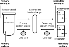
shows a schematic diagram of the Monju plant. The heated sodium in the core is transported from the reactor vessel to the IHX where heat is transferred from the primary sodium system to the secondary sodium system. The heated sodium in the IHX is transported to the SG where steam is produced. The SG consists of an evaporator that produces steam from feed water and a superheater that produces superheated steam for use in a turbine. The heat transfer tubes in the evaporator and the superheater are made of 2.25Cr–1Mo steel and Type 321 stainless steel, respectively. In this study, the following four systems were considered as the main analysis system: the primary sodium, the primary cover gas, the secondary sodium, and the secondary cover gas system. The discussion was limited to the hydrogen behavior in the secondary sodium system because the main hydrogen source was the influx toward the secondary sodium systems from the water–steam systems through the heat transfer tube wall in the SG.
2.3. Analysis approach and conditions
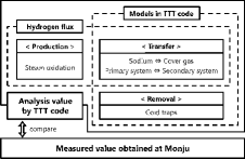
The hydrogen concentration in the sodium coolant and the cover gas is determined by the balance of three components: production, transfer, and removal. Hydrogen is produced through steam oxidation at the water side of the heat transfer tubes in the SG. It transfers through the walls of the heat transfer tubes and between systems in the plant, such as between the sodium coolant and the cover gas and between the primary system and the secondary system. It is removed from the sodium coolant by cold trapping and precipitates as sodium hydride. In comparison with the measured hydrogen concentration in the Monju plant, the hydrogen production term of the three components was estimated using the TTT code, in which the transfer and removal terms were modeled. The main hydrogen source, as previously stated, results from oxidation in the SG, but it is difficult to estimate the amount of hydrogen directly and accurately because this mechanism is not fully understood. There are other hydrogen sources other than just from oxidation; however, their impacts are limited and negligible [Citation11]. Therefore, as illustrated in , which shows the concept of this approach, the hydrogen flux needs to be calculated so that the measured hydrogen concentration is consistent with the estimated hydrogen concentration obtained by iteration in the TTT code. This calculation leads to consistent hydrogen concentrations, simultaneously among the four systems in the plant.
The correction factors implemented in the TTT code and the values used in this study are listed in . The cold trap efficiency, ϵH, is a key factor in estimating the hydrogen flux. It ranged from 0.7 to 0.8 in the 50MWSGTF, which is the large-scale sodium facility constructed to perform research and development for the Monju plant [Citation12]. This value resulted in a design value of the cold trap efficiency at Monju. The permeation correction factors are given as follows, for the IHX and for the SG. The factor for IHX, f3, was 1.0 because the oxygen level in the sodium was maintained at only a few ppm to prevent corrosion on the pipe walls. The factor for SG, f4, was also 1.0 because the hydrogen flux including the corrosion effect was evaluated without bias.
Table 1. Correction factors used in this study.
3. Result and discussion
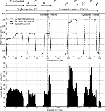
The start-up tests from the first to the seventh test were carried out in 1995 at Monju. The data for hydrogen from the third start-up test to the seventh start-up test were analyzed because the data before the third start-up test were not available. summarizes each operating cycle term and the salient features of the operating conditions involving the SG in start-up tests where the evaporator was singularly operated until the middle of the fifth start-up test and then shifted to the combined operation of the evaporator and superheater. The lines in represent the steam temperature at the evaporator or superheater outlet. In addition to the summary of the operating conditions, the hydrogen flux as a function of the operating time is shown in .
As indicated in , the hydrogen flux fluctuated with the operating conditions such as start-up or shutdown of the SG, as well as the change in the steam temperature. It increased at the beginning of each start-up test with a sharp temperature rise and it decreased with operating time. The hydrogen flux during the single operation fluctuated between approximately 1.0×10⁻¹¹ and 2.2×10⁻¹¹ g-H cm−2 s−1. The combined hydrogen flux during the combined operation fluctuated between approximately 1.2×10⁻¹¹ and 4.7×10⁻¹¹ g-H cm−2 s−1 and increased at the beginning when steam was supplied to the superheater. The peak in the seventh start-up test corresponded to a rise in the hydrazine concentration in feed water, which suppressed the oxygen activity. These profiles suggest that the hydrogen flux should be evaluated in accordance with the operating conditions of the SG.
3.1. Time dependence of hydrogen flux
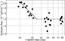
shows the hydrogen flux during the single operation where the steam temperature was approximately 640 K at the evaporator outlet. This selection of steam temperature under the steady-state plant conditions excludes the hydrogen flux fluctuation attributed to the change in steam temperature. The circle symbols represent the hydrogen flux, and the two different line types represent the fitted line and the weighted average value, as mentioned below.
Previous studies have shown that the steam oxidation process is usually stated in the following form [Citation2,3]:
(5) where x refers to the scale thickness, kp refers to the parabolic rate constant, and t refers to the time. Upon differentiating both sides of Equation (5) by time, the hydrogen flux is as follows:
(6) such that the hydrogen flux gives a linear plot on a logarithmic graph. The slope of the hydrogen flux is equal to −0.50 for the oxide layer formation on the heat transfer tubes in the SG. When the hydrogen flux plotted in was fitted by linear regression, the slope was −0.53. Therefore, the steam oxidation reaction had taken place for approximately 35 days before the hydrogen flux stabilized. The oxide layer formation brought about the time dependence of the hydrogen flux. After the hydrogen flux decreasing phase, the weighted average of the flux, which was approximately 1.4×10⁻¹¹ g-H cm−2 s−1, did not seem to follow the parabolic oxidation law. Because the hydrogen flux was calculated with data containing large and rapid changes in factors such as the steam pressure, steam temperature, and feed water flow rate over short time intervals, including shutdown, the hydrogen flux with an unstable oxide layer and detector response may have fluctuated more than the hydrogen flux in operation under steady-state conditions.
The estimated hydrogen flux in this study using the data obtained at Monju is consistent with the previous results using the data obtained at 50MWSGTF, shown in . The data suggested that the hydrogen flux decreased with increasing operating time [Citation12,13]. Because the steam oxidation proceeded during the first start-up test and the second start-up test, which was approximately 50 days, the result of the hydrogen flux in is actually comparable to the results between 50 and 130 days in . Moreover, the time to reach steady hydrogen flux agrees with the duration of approximately 2000 h that was proposed by Roy et al. [Citation1].
Table 2. Transient conditions of hydrogen flux in 50MWSGTF.
The hydrogen flux from the superheater could be estimated if the contribution of the evaporator to the hydrogen flux was constant during the combined operation. When it was evaluated by subtracting the constant hydrogen flux from the combined hydrogen flux, the hydrogen flux from the superheater slightly decreased with increasing operating time. It was, however, not enough to support the time dependence by linear regression. It was also found that the hydrogen flux from the superheater reached stable levels lower than that from the evaporator. Because of the much lower corrosion rate and permeation coefficient for the superheater made of Type 321 stainless steel than those for the evaporator made of 2.25Cr–1Mo steel, it was assumed that the hydrogen flux from the evaporator is the main hydrogen source. This was valid even considering that steam temperature at the superheater outlet was approximately 383 K higher than that at the evaporator outlet.
3.2. Steam temperature dependence of hydrogen flux
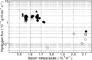
From the evaluation of the time dependence, the oxide layer formation caused the hydrogen flux to change until 35 days, even if the steam temperature was constant. Therefore, it was required to analyze how the hydrogen flux during the single operation depends on the steam temperature, before and after 35 days separately. shows the hydrogen flux as a function of the inverse steam temperature at the evaporator outlet. The closed-circle symbols represent the hydrogen flux before 35 days, the open-circle symbols represent the flux after 35 days, and the triangle symbols represent the flux of other FBRs and facilities as shown in (CGVS, Phenix, 50MWSGTF, Prototype Fast Reactor). The hydrogen flux obtained in the temperature range from 473 to 753 K agreed well with the hydrogen fluxes of other FBRs and facilities in the temperature range from 603 to 653 K [Citation1,Citation14], and also followed the Arrhenius relation. The agreement among the data is remarkable, considering that the operating conditions and the measurement methods and analysis of the hydrogen flux were different in each case.
Table 3. Comparison of hydrogen flux in other FBRs and facilities.
The temperature dependence evaluated using the Arrhenius relation suggests that to some degree the activation energy controls the hydrogen flux. In the process where hydrogen is formed as the by-product of the steam oxidation on the surface of the heat transfer tubes and diffuses toward the secondary sodium through the heat transfer tubes in the SG, both processes play an important role in the evaluation of hydrogen flux. According to Paterson et al., the activation energies in each process follow the parabolic constant, kp [Citation15],
(7) and the permeation coefficient, κH [Citation16],
(8) where T is the metal temperature and R is the gas constant. The activation energies are shown in . From the comparison of the hydrogen flux with the activation energies in each process, the diffusion process controls the hydrogen flux in both results before and after 35 days. The data at low steam temperatures are somewhat scattered compared to those at high steam temperatures. This can be attributed to the transient operating conditions, such as a rise in the steam temperature and a change in the steam flow rate. The spalling of the steam-side oxide layer produced on the heat transfer tube can also affect the increase in the hydrogen flux during a sudden drop in temperature. In addition to these uncertainties, the temperature dependence of the hydrogen flux was not evaluated with the metal temperature that had a distribution along the axial direction, but with the steam temperature at the evaporator outlet. The results suggest that these factors make the difference in the activation energy between the hydrogen flux in this study and the permeation coefficient from reference data.
Table 4. Comparison of activation energies in each process.
4. Conclusion
The hydrogen flux from the SG in the power rising test of Monju was evaluated as the main hydrogen source. The following results were obtained.
The hydrogen flux in the evaporator gradually decreased with the elapse time until 30–40 days following the parabolic oxidation law. Following this period, the flux did not follow the law for the rest of the duration.
The comparison of the slope obtained by linear regression suggested that the hydrogen flux was mainly controlled by the permeation process, rather than the steam oxidation process.
It was confirmed that the hydrogen flux in this study was consistent with reference data and was evaluated over a wide steam temperature range.
Acknowledgements
We are deeply grateful to Dr. S. Miyahara, Dr. K. Tamayama, and Dr. H. Nishi of the FBR Plant Engineering Center, for their assistance in preparation of this paper. We also would like to express our gratitude to the Fast Breeder Reactor Research and Development Center, Monju.
References
- Roy P, Rodgers DN. Hydrogen burden from the steam side corrosion in sodium-heated steam generators. Nucl Technol. 1978;39:213–215.
- Tomlinson L, Cory NJ. Hydrogen emission during the steam oxidation of ferritic steels: kinetics and mechanism. Corros Sci. 1989;29:939–965.
- Cory NJ, Herrington TM, Tomlinson L. Hydrogen emission during the steam oxidation of ferritic steels: experimental technique. Corros Sci. 1988;28:333–342.
- Iizawa K, Torii T. Hydrogen and tritium behaviour in Monju; validation of an analysis code for tritium transport in fast reactor system, TTT, and estimation for Monju full power operation in future. Japan: Japan Nuclear Fuel Cycle Development Institute; 1999. Japanese.
- Iizawa K, Torii T. Development of a tritium transport analysis code for the LMFBR system. Japan: Japan Nuclear Fuel Cycle Development Institute; 2001. Japanese.
- Vissers DR. A hydrogen activity meter for liquid sodium and its application to hydrogen solubility measurements. Nucl Technol. 1974;21:235–244.
- Gwyther JR, Whittingham AC. The kinetics of hydrogen removal from liquid sodium. In: Borgstedt HU, editor. Material behavior and physical chemistry in liquid metal systems. New York (NY): Plenum Press; 1982. p. 335–343.
- Rohrig HD, Hecker R, Blumensaat J, Schaefer J. Studies on the permeation of hydrogen and tritium in nuclear process heat installations. Nucl Eng Des. 1975;34:157–167.
- Gilbert ER, Allen RP, Baldwin DL, Bell RD, Brimhall JL. Tritium permeation and related studies on barrier treated 316 stainless steel. Fusion Technol. 1992;21:739–744.
- Hollenberg GW, Simonen EP, Kalinin G, Terlain A. Tritium/hydrogen barrier development. Fusion Eng Des. 1995;28:190–208.
- Nei H. Hydrogen behavior in FBR secondary cooling system. J At Energy Soc Jpn. 1979;21:405–410. Japanese.
- Kaneko Y, Nishikimi M, Shirato S, Tsuchiya T, Fukuda T. Experiments on the water leak detection systems in the 50MW Steam Generator Test Facility -9-; cold trap efficiency test, hydrogen background, concentration test, hydrogen flux through tube test. Japan: Power Reactor and Nuclear Fuel Development Corporation; 1985. Japanese.
- The Cold Trap Study Group. Hydrogen behavior and removal in sodium cooled fast breeder reactor. Japan: Power Reactor and Nuclear Fuel Development Corporation; 1980. Japanese.
- Nuclear Power Technology Development Section. Fast reactor database 2006 update. Vienna: International Atomic Energy Agency; 2007.
- Paterson SR, Moser R, Rettig TR. The oxidation of boiler tubes. Proceedings of the International Conference on Interaction of Iron-Based Materials with Water and Steam; 1992 June 3–5; Heidelberg, Germany.
- Chang PL, Bennett WDG. Diffusion of hydrogen in iron and iron alloys at elevated temperatures. J Iron Steel Inst. 1952;179:205–213.

