Abstract
A new correction technique to capture the spectral interference effect on collapsed cross sections, which focuses on application to the pin-by-pin boiling water reactor (BWR) core analysis, is proposed. The spectral interference effect, which is caused by adjacent loadings of different types of fuel assemblies, has relationship with variations of neutron leakage in each pin-cell from the viewpoint of neutron balance. Variation of neutron leakage affects neutron spectrum and thus the neutron leakage is considered to be important to correct coarse-group cross sections used in core calculations. We focus on the neutron leakage in each pin-cell and use it as a correction index (i.e., a leakage index (LI)), which is defined as the volume-averaged neutron leakage in a pin-cell. By utilizing the leakage index, we represent the variations of coarse-group cross sections as the linear combination of LIs. In order to verify and discuss the applicability of the present correction technique, two-dimensional benchmark calculations considering typical characteristics of BWR cores are carried out. From the calculation results, the present correction technique well reproduces the reference coarse-group cross sections and improves the calculation accuracies.
1. Introduction
Nuclear cross sections strongly depend on neutron energy (e.g., their behaviors in resonance regions). In order to directly capture such energy dependence of cross sections and accurately calculate several types of reaction rates, several tens of thousand of energy groups should be used in core calculations. However, such ultra-fine-group calculations are impractical for core analysis from the viewpoint of computational time and required memory. Therefore, in the conventional core analysis, the number of energy groups is reduced as the calculation geometry becomes large (i.e., energy collapsing of cross sections is performed). However, the energy collapsing through conventional lattice physics calculations does not directly take into account the spectral interference effect, which is also called as the neighborhood effect or the spectral mismatch effect. Several corrections of cross sections considering the spectral interference effect are performed in core calculations in engineering or empirical manner. The spectral interference effect induces the variations of neutron spectrum and causes the spatial homogenization and the energy collapsing errors of cross sections.
In the conventional boiling water reactor (BWR) core analysis with lattice physics and core calculations, assembly-homogenized coarse-group (one to three group(s)) cross sections are obtained by spatial average and energetic collapse of heterogeneous fine-group (dozens to a few hundred groups) cross sections [Citation1,2]. These spatial homogenization and energy collapsing are performed through lattice physics calculations in single assembly geometries with the reflective boundary condition. Namely, neutron fluxes in single assembly geometries are used in the spatial homogenization and the energy collapsing of cross sections. However, neutron fluxes in single assembly geometries are generally different from those in core geometries, since the spatial and the energetic distribution of neutron fluxes become different in core geometries by the spectral interference effect due to the adjacent loadings of different types of fuel assemblies. As a result, appropriate cross sections for core calculations (i.e., cross sections directly homogenized and collapsed in core geometries) are different from those calculated through lattice physics calculations in single assembly geometries. Therefore, a correction for cross sections considering the spectral interference effect is necessary.
In order to correct the cross sections, several techniques have been studied. In the conventional core analysis in two or three groups, the spectral index (SI), which is the ratio of fast to thermal fluxes with the energy boundary on 0.625 eV, has been traditionally used and the variations of cross sections are represented as the functions of SI [Citation3,4]. Moreover, in the recent studies, on-the-fly boundary condition adjustments have been investigated in pressurized water reactor core geometries [Citation5,6]. In such on-the-fly correction techniques, cross sections are recalculated through the iterations of lattice physics calculations with the updated albedo boundary conditions, which are obtained by the boundary conditions of the target fuel assemblies in core calculations.
Recently, as a next generation core analysis method, the pin-by-pin fine mesh core calculation method for BWR core analysis has been studied [Citation7,8]. The previous study indicates that the pin-by-pin approach for BWR core analysis has good accuracy to evaluate important parameters for highly heterogeneous cores (e.g., mixed-oxide (MOX) or high-burnup fuel loaded core). In BWR fuel assemblies, significant variation on energetic distribution of neutron spectrum is observed due to complicated geometries (e.g., a large enrichment splitting, Gd-bearing rods, and control rod insertion). In order to capture significant variation on energetic distribution of neutron spectrum in BWR fuel assemblies or in highly heterogeneous cores and to obtain higher prediction accuracy, utilization of finer energy group structure in core calculations is desirable. For example, eight- or nine-group structure is used in the previous study of the pin-by-pin approach for light water reactor core analysis [Citation7–9]. However, even if we utilize such finer energy group structure, the spectral interference effect on the energy collapsing should be still taken into account and several correction techniques considering this effect are necessary. For such finer group calculations, in which variations on energetic distribution of neutron spectrum are considered in more detail, the conventional SI correction technique based on engineering or empirical approaches would not be valid since the SI only considers the ratio of fast to thermal fluxes. Namely, even if the SI indicates a same value, finer group cross sections would be different due to variations of fine-group neutron spectrum within coarse groups. Furthermore, since various types of fuel assembly are loaded into BWR cores with complicated depletion histories (e.g., void history and control rod history), the on-the-fly approaches would require larger computation time for the pin-by-pin BWR core analysis.
In the present paper, we focus on the spectral interference effect on the energy collapsing and propose a new correction technique for the coarse-group cross sections used in pin-by-pin core analysis of BWRs. Some theoretical descriptions related to the present study are described in Section 2. The verifications of the present correction technique are shown in Section 3 through numerical benchmark calculations. Finally, the concluding remarks are given in Section 4.
2. Methodology
In this section, the root cause for the variations of coarse-group cross sections in single and colorset assembly geometries (i.e., lattice physics and core calculations) is discussed at first. Then, the theoretical descriptions for the new correction technique proposed in the present study are described.
2.1. Overview of energy collapsing
First, we discuss the reason for the variations of coarse-group cross sections in single and colorset assembly geometries from the viewpoint of mathematical formulations for the energy collapsing. In the conventional core analysis with lattice physics and core calculations, coarse-group cross sections for core calculations are obtained by collapsing fine-group cross sections with fine-group neutron fluxes through lattice physics calculations in single assembly geometries:
(1) where Σ and φ are the macroscopic cross section and the neutron flux, respectively. The subscripts of x, g, and G represent the reaction type (i.e., absorption, fission, production cross sections, scattering matrices, and diffusion coefficients), the fine-group index, and the coarse-group index, respectively. By using Equation (1), the variation of coarse-group cross sections obtained by single and colorset assembly calculations is given by
(2) where w is the neutron flux weight of particular energy group. The superscripts ‘single’ and ‘colorset’ represent single and colorset assembly calculations, respectively. Note that the fine-group cross sections are assumed to be the same in single and colorset assembly calculations in Equation (2). According to Equation (2), the variations of fine-group flux weights (i.e., the energetic distribution of fine-group neutron spectrum) are necessary to correct the coarse-group cross sections due to the spectral interference effect.
From the viewpoint of actual physical phenomena, we consider that the variations of fine-group neutron fluxes are caused by those of neutron leakage (i.e., the boundary conditions of fuel assemblies). Then, the variations of fine-group neutron fluxes cause those of coarse-group cross sections. In order to capture such physical phenomena, several approaches have been studied (e.g., neutron current to flux ratios on mesh surfaces is considered as a correction index, fine-group neutron fluxes are reconstructed, or several colorset conditions are combined [Citation10–12]). In the present study, we consider that the variations of coarse-group cross sections are functions of neutron leakage and propose a new correction technique for coarse-group cross sections considering the spectral interference effect by focusing on the variations of neutron leakage.
2.2. Correction technique using leakage index
In order to discuss the variations of coarse-group cross sections through neutron leakage, we utilize the generalized perturbation theory based on the diffusion theory and derive the relationship between the variations of coarse-group cross sections and neutron leakage [Citation13]. It should be noted that we treat the spectral interference effect as perturbations of boundary condition on fuel assembly in focus. Thus, the following theoretical descriptions assume single assembly geometries with variations of boundary condition.
First, let us start with the k-effective eigenvalue equation based on diffusion theory:
(3) where keff and φ are the k-effective (the effective multiplication factor) and the neutron flux, respectively. The operators L, A, and F correspond to the neutron leakage, the neutron loss and production by absorption and scattering reactions, and the neutron production by fission reactions, respectively. From here, we consider the multi-group diffusion equation. The operators L, A, and F in Equation (3) are written as
(4) where D, Σr, νΣf, Σs, and χ are the diffusion coefficient, the removal cross section, the production cross section, the scattering cross section, and the fission spectrum, respectively. The vector of
indicates the space. The subscript of g represents the energy group index. By using the operator M, which is the diffusion operator, Equation (3) is re-written as
(5)
Now, let us consider an arbitrary reaction rate ratio:
(6) where R, Σ, ϕ, are the reaction rate ratio, the cross section, and the neutron flux, respectively. The bracket denotes the integration over space and the summation over neutron energy groups. In order to discuss coarse-group cross sections in Equation (1),
and
in Equation (6) are determined as
(7) where Σx is the macroscopic cross sections of reaction x. The subscript of g, G, and m represent the fine energy group, the coarse energy group, and the homogenized mesh indices, respectively. In Equation (7),
is defined as
(8) where Vm is the volume space of homogenized mesh m. By substituting Equations (7) and (8) into Equation (6), coarse-group cross sections in Equation (1) are represented as
(9)
The sensitivity coefficient of coarse-group cross sections for an arbitrary parameter is defined as
(10) where S and X are the sensitivity coefficient and the arbitrary parameter, respectively. With common derivation in the generalized perturbation theory [Citation13], Equation (10) is written as follows by neglecting the second-order variations:
(11)
The first term in the right hand side of Equation (11) is the direct term, which expresses the variation of reaction rate due to the perturbation of . The second and third terms are the indirect terms, which express the variation of reaction rate due to the perturbation of neutron flux.
Then, in order to estimate the indirect terms (i.e., the second and the third terms in the right hand side of Equation (11)), we introduce the generalized adjoint flux, which is calculated by the adjoint equation described as
(12) where Γ+ and Q+ are the generalized adjoint flux and the generalized adjoint source, respectively. For the reaction rate ratio shown in Equation (6), the generalized adjoint source is given as
(13)
For energy collapsing of cross sections shown in Equation (9), by using Equation (7), Equation (13) is re-written as
(14)
Thus, from Equation (12), the generalized adjoint flux for energy collapsing of cross sections satisfies
(15)
Multiplying both sides of Equation (15) by , integrating over space, and summing over neutron energy groups, we can obtain
(16)
In Equation (5), if we consider the variation of operator M and the neutron flux, they satisfy the following relation:
(17)
Here, we also assume that the second-order variations are negligible and consider , then we obtain
(18)
Thus, multiplying both sides of Equation (18) by , integrating over space, summing over neutron energy groups, and dividing by dX, we can obtain
(19)
By using the property of adjoint operator for the left hand side of Equation (19), we can obtain
(20)
From Equations (19) and (20), Equation (16) is re-written as
(21)
Therefore, by using Equation (21), the sensitivity coefficient of coarse-group cross sections for an arbitrary parameter shown in Equation (11) is given by
(22)
In the present study, we assume that the fine-group cross sections do not change when an arbitrary parameter X is perturbed. Thus, Equation (22) is approximated as
(23)
Finally, let us consider the variation of neutron leakage due to the spectral interference effect in Equation (23). In order to express the neutron leakage, we newly introduce a LI defined by
(24) which is an index parameter related to neutron leakage and is defined as a volume-averaged neutron leakage. From the viewpoint of neutron balance in the k-effective eigenvalue calculation, the LI is calculated by
(25)
From Equation (25), the dimension of LI is same as macroscopic cross sections. That is, the LI is also considered as a kind of macroscopic cross section related to the neutron leakage.
By utilizing the LI calculated by Equation (25), the operator L is approximated as
(26) Thus, the variation of operator M is written as
(27)
It should be noted that only is changed as shown in Equation (27) since we assume that the variations of neutron spectrum are only occurred by the neutron leakage due to the spectral interference effect (i.e., cross sections are not changed). Therefore, by using Equations (26) and (27), Equation (23) is approximated as
(28) where
is defined as
(29)
In Equation (28), δ is the kronecker delta. Note that, as shown in Equations (28) and (29), the sensitivity coefficient of coarse-group cross sections is only represented by the LIs over the volume space of target homogenized mesh m. In reality, neutron leakage changes for various reasons (e.g., variation of boundary condition and cross section change) and it has complicated spatial and energetic relationships. For example, cross section changes such as control rod insertion in another fuel assembly can vary neutron leakage at a pin-cell in focus through spatial and energetic coupling as a critical system. However, by introducing the LIs, which correspond to macroscopic ‘leakage’ cross sections, the variations of neutron leakage due to the spectral interference effect can be considered as perturbation of LIs in the target homogenized mesh. This greatly simplifies the situation and is a great advantage of using the LIs. Therefore, Equation (28) is re-written as
(30)
By considering the summation of variations of fine-group LIs, the variations of coarse-group cross sections can be estimated as
(31)
In Equation (31), the variations of coarse-group cross sections are estimated by integrating the product of fine-group-generalized adjoint flux, fine-group neutron flux, and the variation of fine-group LI over space and by summing it over neutron energy groups. However, since core calculations in the conventional core analysis are performed with coarse-group cross sections, they cannot directly estimate the fine-group-generalized adjoint fluxes, the fine-group neutron fluxes, and the variations of fine-group LIs in the right hand side of Equation (31). Thus, it is necessary to simplify Equation (31) based on coarse-group parameters.
In the present study, we assume the relationship between the variations of fine-group and coarse-group LIs as
(32) Thus Equation (31) is re-written as
(33) where
(34) which is the coupling coefficient defined as a variation of Gth group cross sections per a variation of G′th group LI (i.e.,
corresponds to a sensitivity coefficient of coarse-group cross sections to coarse-group LIs).
In Equations (33) and (34), the fine-group-generalized adjoint fluxes and neutron fluxes are still necessary to calculate the coupling coefficients though the variations of coarse-group cross sections approximately estimated by the variations of coarse-group LIs. Thus, in the present study, Equation (34) is not used to calculate the coupling coefficients since utilization of Equation (34) requires large computational load to calculate the fine-group-generalized adjoint fluxes. The details of calculation procedures to estimate the coupling coefficients are shown in the next subsection. The discussions from the viewpoint of computational load are described in Section 3.1.2.
For the spatial differences of homogenized meshes, Equation (33) is re-written as
(35) where the superscript ‘single’ and ‘colorset’ represent single and colorset assembly calculations, respectively. In the present study, Equation (35) is used for all reaction types of cross sections (i.e., absorption, fission, production cross sections, scattering matrices, and
diffusion coefficients) since they are collapsed with neutron fluxes as Equation (1). The applicability of Equation (35), which is derived from Equation (31), is verified through numerical calculations in Section 3.
2.3. Calculation procedure to estimate coupling coefficients of leakage index
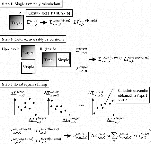
In the previous subsection, we utilize the generalized perturbation theory and approximately derive the relationship between the variations of coarse-group cross sections and LIs as shown in Equation (35). According to Equation (35), the coupling coefficients are necessary to estimate the variations of coarse-group cross sections in prior to core calculations. However, the fine-group-generalized adjoint fluxes and neutron fluxes are necessary to directly calculate the coupling coefficients based on Equation (34) and such calculation is impractical from the viewpoint of computational load. Therefore, in the present study, we perform several colorset assembly calculations to obtain the relationship between the variations of coarse-group cross sections and LIs. Then we calculate the coupling coefficients by the least-squares approximation for the variations of coarse-group cross sections and LIs. By adopting such colorset assembly calculations, calculations of fine-group-generalized adjoint fluxes and neutron fluxes are not necessary. In this subsection, the details of calculation procedures to estimate the coupling coefficients are described.
Equation (35) is derived under the assumption that the spectral interference effect is treated as the perturbations of boundary condition on target fuel assemblies. In order to calculate the coupling coefficients, it is necessary to simulate the perturbations of boundary conditions due to the spectral interference effect. In the present study, we carry out several colorset assembly calculations to perturb the boundary conditions on the target fuel assemblies. However, we generally do not have prior knowledge which types of fuel assemblies (e.g., the assembly exposure and the enrichment distribution) will be loaded into the adjacent regions of target fuel assembly. Therefore, we perform various simplified colorset assembly calculations and calculate the coupling coefficients. For various simplified colorset assembly calculations, we prepare some simplified fuel assemblies.
In this subsection, the calculation procedure to calculate the coupling coefficients of LIs in Equation (35) is described as first, then the details of target and simplified fuel assemblies are shown.
The overview of the calculation procedure to obtain the relationship between the variations of coarse-group cross sections and those of LIs and to calculate the coupling coefficients in Equation (35) is shown in .
As shown in , first, fine-group calculations are carried out in single assembly geometries, which consist of the target fuel assembly. Coarse-group cross sections (Σtarget(single)m, G) are collapsed in single assembly geometries and coarse-group LIs (LItarget(single)m, G) are estimated by utilizing the calculation results (i.e., the neutron fluxes and the k-effective).
Second, fine-group calculations are carried out in colorset assembly geometries, which consist of the target and the simplified fuel assemblies. Coarse-group cross sections (Σtarget(colorset)m, G) are directly collapsed in colorset assembly geometries and coarse-group LIs (LItarget(colorset)m, G) are estimated by utilizing the calculation results (i.e., the neutron fluxes and the k-effective). Note that the fine-group cross sections (Σtargetx, m, g and Σsimplex, m, g) used in steps 1 and 2 are the same and they are preliminarily calculated in lattice physics code. The details of preparation of fine-group cross sections are described in Section 3.1.
In the colorset assembly calculations, the colorset assembly geometries should be chosen to cover actual impacts of spectral interference effect. In the present study, we assume that actual impacts of spectral interference effect can be simulated in two assembly geometries with the reflective boundary condition, in which the target and the simplified fuel assemblies are adjacently loaded. This assumption is justified since the spectral interference effect is mainly observed in the assembly peripheral meshes and the actual impacts of spectral interference effect can be decomposed into the impact from each assembly surface. Thus, by considering the symmetry of fuel assembly, two types of two assembly geometries shown in are used in the present study. It should be noted that the control rod insertion for two assembly geometries shown in is different from that for actual operating core (i.e., the control rods are not inserted into neighboring control cells). However, in lattice physics calculations (single assembly geometries with the reflective boundary condition), the control rods are assumed to be inserted into neighboring control cells. Moreover, if the control rod insertion for actual operating core is simulated, colorset assembly geometries become large and large computational load is necessary. Thus, in order to simplify colorset assembly geometries and to reduce computational load, we use the two assembly geometries with approximate treatment of the control rod insertion.
Finally, the coupling coefficients of LIs (), which correspond to
in Equation (35), are calculated for each pin-cell. The least-squares approximation for the relationship between coarse-group cross sections and LIs obtained in steps 1 and 2 is used to estimate the coupling coefficients.
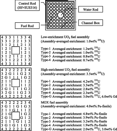
In the present study, three types of 8 × 8 BWR fuel assemblies shown in are used for the target fuel assemblies.
As shown in , the low-enrichment UO2 (assembly-averaged enrichment: 1.0 wt% 235U), the high-enrichment UO2 (assembly-averaged enrichment: 3.5 wt% 235U), and the MOX (assembly-averaged enrichment: 4.0 wt% Pu-fissile) fuel assemblies are used. The geometry of these 8 × 8 fuel assemblies is taken from [Citation14]. The fuel rod enrichment distributions of them are manually decided.
In general, the enrichment distribution of fuel assemblies, which will be loaded into the adjacent regions of target fuel assembly, is unknown in prior to core calculations. Thus, six types of fuel assemblies with the uniform enrichment distribution are used for simplified fuel assemblies. The fuel rod enrichments are 1.0 wt% 235U, 3.0 wt% 235U, 5.0 wt% 235U, 3.0 wt% Pu-fissile, 4.0 wt% Pu-fissile, and 5.0 wt% Pu-fissile. Enrichments of 235U and Pu-fissile are chosen to cover the values used in typical BWR fuel assemblies. The geometry of simplified fuel assemblies is the same as that of target fuel assemblies (i.e., the simplified fuel assemblies are also 8 × 8 BWR fuel assemblies).
3. Numerical calculations
3.1. Calculation conditions
3.1.1. Preparation of pin-cell-averaged cross sections
The pin-cell-averaged cross sections used in the present study are calculated by the HELIOS code in 47 energy groups [Citation15]. In the HELIOS code, the depletion calculation is performed in single assembly geometry with the reflective boundary condition. The void fraction, the control rod position, and the power density are fixed during the depletion calculation. Through the depletion calculations, we obtain the pin-cell-averaged fine-group cross sections at 0, 15, 30, 45, and 60 GWd/t (assembly-averaged exposure). The fine-group cross sections at 0, 15, 30, 45, and 60 GWd/t are used to construct the two assembly geometries shown in Section 2.3 and the 4 × 4 colorset assembly geometries as described below.
In order to reduce the spatial homogenization errors, the superhomogenization (SPH) method is applied for 47-group pin-cell-averaged cross sections in single assembly geometries [Citation16]. Note that the SPH method is not applied to reduce the energy collapsing errors in the present paper.
In general, the SPH factor changes due to the spectral interference effect similar to the coarse-group cross sections. In order to apply the SPH method to reduce the energy collapsing errors, consideration of the spectral interference effect on SPH factor is necessary. However, the treatment of the SPH factor considering the spectral interference effect is out of the scope of the present paper. We focus on the reproduction of reference coarse-group cross sections, which are directly obtained by colorset assembly calculations, in the present paper. Treatment of the SPH factor will be addressed in a future study.
3.1.2. Estimations of coupling coefficients of leakage index
In the present correction technique using the leakage index, the two assembly geometries, which consist of the target and the simplified fuel assemblies, are used. Through the two assembly calculations, the perturbations of boundary conditions due to the spectral interference effect are simulated and the coupling coefficients of LIs are calculated.
In the present paper, we carry out 36 patterns of two assembly calculations for one target fuel assembly. These 36 patterns of two assembly geometries are determined by the combinations of calculation conditions for simplified fuel assemblies as follows:
Fuel rod enrichment (six patterns): 1.0 wt% 235U, 3.0 wt% 235U, 5.0 wt% 235U, 3.0 wt% Pu-fissile, 4.0 wt% Pu-fissile, and 5.0 wt% Pu-fissile.
Assembly-averaged exposure (three patterns): 0, 30, and 60 GWd/t.
Loading position of simplified fuel assemblies (two patterns): Upper and right sides for the target fuel assembly.
Let us compare the computational load to calculate the coupling coefficients of LIs in Equation (35). We can use two approaches to calculate the coupling coefficients (i.e., by using the fine-group-generalized adjoint fluxes and neutron fluxes based on Equation (34), or by applying the least-squares approximation for the calculation results obtained by the two assembly calculations).
In order to calculate the fine-group-generalized adjoint fluxes using Equation (13), different generalized adjoint sources should be set for each pin-cell meshes, reaction types, and coarse energy groups. When we calculate the fine-group-generalized adjoint fluxes for absorption, fission, production cross sections, scattering matrices, and diffusion coefficients with eight groups in 8 × 8 BWR fuel assembly, approximately 5000 single assembly calculations are necessary. Note that the number of pin-cell meshes of 8 × 8 BWR fuel assembly is 55 by considering the symmetry of 8 × 8 BWR fuel assembly. In general, in order to calculate the generalized adjoint fluxes, complicated iteration calculations are necessary. Thus, in reality, several tens of thousand single assembly calculations are necessary.
On the other hand, when we carry out the 36 patterns of two assembly calculations, its computational load approximately corresponds to 150 (∼36 × 4) single assembly calculations. Note that we assume that the computational load of two assembly calculations is comparable to four single assembly calculations.
Therefore, the least-squares approximation for the relationships between the coarse-group cross sections and LIs obtained by the two assembly calculations is more efficient than the direct calculations based on Equation (34).
3.1.3. Verifications of present correction technique
In order to verify the applicability of the present correction technique, two-dimensional benchmark problems considering typical characteristics of BWR cores are carried out. In the benchmark problems, we consider the energy collapsing of cross sections from 47 to 4 and 8 energy groups, whose structures are shown in [Citation17].
Table 1. Energy group structure.
Through the numerical verifications with four- and eight-energy-group structures, first, we discuss the applicability of the present correction technique for finer group cross sections. Next, we also discuss the degree of freedom of correction in the present technique, which relates to the performance of cross section reproductions. These discussions will be done by comparing the calculation results between different energy group structures.
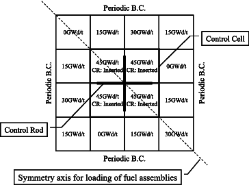
In the present paper, we use 4 × 4 colorset assembly geometry with the periodic boundary condition shown in , which consists of different types of 8 × 8 BWR fuel assemblies shown in .
In , 2 × 2 fuel assemblies, which are located in the center of 4 × 4 colorset assembly geometry, simulate a control cell and are same fuel assemblies (i.e., the assembly-averaged exposure and the type of fuel assembly are same). For other fuel assemblies loaded around the control cell the assembly-averaged exposures are fixed as shown in and the types of fuel assemblies are randomly determined considering the diagonal symmetry of 4 × 4 colorset assembly geometry. Through these procedures, we determine approximately 6500 patterns of 4 × 4 colorset assembly geometries, which are combinations of three types of fuel assemblies for the control cell and surrounding seven assemblies (i.e., 38 patterns). Note that the assembly-averaged void fraction is 40%. Since we assume that the cycle length is 15 GWd/t and consider the loading pattern of fuel assemblies in the beginning of cycle, the assembly-averaged exposure is chosen from 0, 15, 30, and 45 GWd/t.
3.2. Calculation procedure to correct coarse-group cross sections
In the present correction technique using the leakage index, the coarse-group cross sections are corrected by the following procedures. Note that iteration calculations are necessary to update coarse-group cross sections since the LIs in the target colorset fuel assembly (i.e., LIm, G in Equation (35)) are unknown.
Single assembly calculations in coarse group are carried out for all types of fuel assemblies, which are used in the target colorset assembly geometry. Through such single assembly calculations, LIsinglem, G in Equation (35) are calculated for each pin-cell meshes.
Target colorset assembly calculation in coarse group is carried out with the uncorrected coarse-group cross sections. Namely,
and dΣx, m, G in Equation (35) are assumed to be LIsinglem, G and zero, respectively, in this step.
By using the neutron fluxes and the k-effective obtained by the target colorset assembly calculation, the LIs perturbed by the spectral interference effect calculated. Namely,
in Equation (35) are updated.
Based on Equation (35), the variations of coarse-group cross sections are recalculated by the LIs obtained in steps (1) and (3) (i.e., LIsinglem, G and
) and the coupling coefficients of LIs pre-calculated in Section 2.3.
Target colorset assembly calculation in coarse group is carried out with the corrected coarse-group cross sections obtained in step (4).
Steps (3)–(5) are repeated until the k-infinity and the pin-by-pin fission rate distribution of the target colorset assembly calculation are converged.
3.3. Calculation results and remarks
In order to verify the applicability of the present correction technique, we compare the k-infinities and the pin-by-pin fission rate distributions of several 4 × 4 colorset assembly geometries. The pin-by-pin (cell-homogenized) calculations in the single and the colorset assembly geometries are performed by the diffusion method. The finite difference method is used for the spatial discretization in the diffusion method. The absolute value of relative difference of k-infinity and the root-mean-square (RMS) difference of pin-by-pin fission rate distribution are calculated as
(36)
(37) where Δkinf, ΔRf,RMS, Rf,i, and Nfuel mesh are the absolute value of relative difference of k-infinity, the RMS difference of pin-by-pin fission rate distribution, the pin-by-pin fission rate on fuel mesh m, and the total number of fuel meshes, respectively. The superscripts ‘calculated’ and ‘reference’ represent the calculations with the coarse-group cross sections corrected (or not corrected) by the present correction technique and those with the reference cross sections, respectively. In the present verifications, the coarse-group cross sections obtained by direct collapsing of fine-group cross sections in the target colorset assembly geometry are used as the reference cross sections. Note that reproducibility of coarse-group cross section by applying the present correction technique is major interest in the present paper. Thus, the SPH method is used to reduce the spatial homogenization errors but is not used to reduce the energy collapsing errors. The direct comparisons with the fine-group or the HELIOS calculations will be addressed in a future study since the treatment of the SPH factor considering the spectral interference effect has not been investigated yet as described previously.
The absolute value of relative difference of k-infinities and the RMS difference of pin-by-pin fission rate distributions calculated with four- and eight-group cross sections are shown in and , respectively. In , these calculation results are summarized. In and and , the calculation results obtained by the coarse-group cross sections corrected by the present correction technique and those not corrected (i.e., only collapsed in single assembly geometries) are represented as ‘Corrected’ and ‘Not corrected’, respectively.
Table 2. Summary of calculation results.
Figure 4. Frequency distributions of k-infinity and pin-by-pin fission rate distribution (four groups).
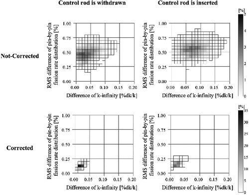
Figure 5. Frequency distributions of k-infinity and pin-by-pin fission rate distribution (eight groups).
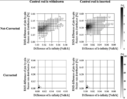
From and , the calculation accuracies of k-infinity and pin-by-pin fission rate distribution are improved by applying the present correction technique using the LIs. These improvements are observed on all calculation cases, whose loading patterns are randomly determined. Therefore, the present correction technique using the LIs is valid to correct coarse-group cross sections considering the spectral interference effect. From , the improvements of calculation accuracies are observed for the energy collapsing from 47 to both of 4 and 8 energy groups. Thus, Equation (35), which is derived from Equation (30), would be valid and can capture the impacts of variations of neutron leakages due to the spectral interference effect.
In order to estimate the reproducibility of coarse-group cross sections calculated by Equation (35), we also estimate the RMS difference of coarse-group cross sections, which is potentially caused on the present correction technique, as
(38) where R and Ntwo assembly geometry are the RMS difference of coarse-group cross sections and the number of two assembly geometries used to calculate the coupling coefficients (i.e., quadruple of the number of simplified fuel assemblies), respectively.
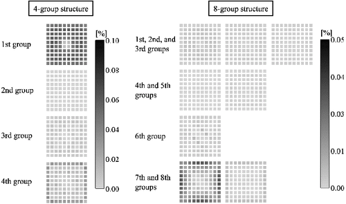
The RMS differences of absorption cross sections and diffusion coefficients in the MOX fuel assembly without the control rod are shown in and , respectively. Note that the assembly-averaged void fraction and the assembly-averaged exposure of MOX fuel assembly are 40% and 0 GWd/t, respectively.
Figure 6. RMS differences of absorption cross sections in MOX fuel assembly (void fraction: 40%, exposure: 0 GWd/t).
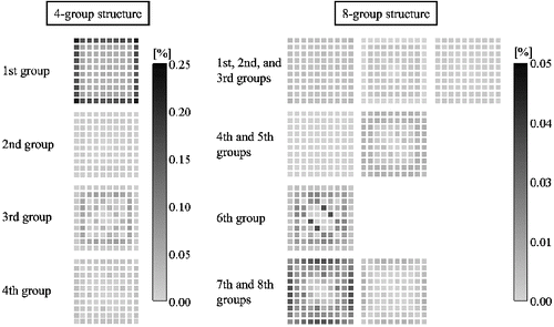
Figure 7. RMS differences of diffusion coefficients in MOX fuel assembly (void fraction: 40%, exposure: 0 GWd/t).
From , the RMS differences of sixth group absorption cross sections in eight-group structures are
about 0.05% in water rod meshes and those of seventh group absorption cross sections are about 0.05% in peripheral meshes. However, the RMS differences of other group absorption cross sections are less than 0.01%. In four-group structures, the RMS differences of absorption cross sections have tendencies different from those in eight-group structures. They are generally larger than those in eight-group structures. The RMS differences of first group absorption cross sections in four-group structures are about 0.25% in peripheral meshes. From , the RMS differences of seventh group diffusion coefficients in eight-group structures are about 0.04% in peripheral meshes and those of other group diffusion coefficients are less than 0.01%. On the other hand, in four-group structures, the RMS differences of first group diffusion coefficients become much larger in almost all meshes. Note that similar results are observed for other types of reactions (e.g., production, fission, and scattering) and for other types of fuel assemblies (i.e., the low-enrichment UO2 and the high-enrichment UO2 fuel assemblies).
From the results described the above, the differences of cross sections in four-group structures become larger than those in eight-group structures and they are mainly observed in peripheral meshes, in which the impact of the spectral interference effect generally becomes large. The impact of spectral interference effect in eight groups are generally smaller than that in four groups and the degree of freedom for the present correction technique in eight groups is greater than that in four groups as shown in Equation (35). Therefore, since the reproducibility of eight-group cross sections becomes better than that of four-group cross sections, the differences of k-infinity and pin-by-pin fission rate distribution in eight-group structures shown in and and are smaller than those in four-group structures.
4. Conclusions
In this paper, we propose a new correction technique for coarse-group cross sections in the pin-by-pin core calculations considering the spectral interference effect, which is caused by the adjacent loading of different types of fuel assemblies.
In the present correction technique, we focus on the perturbation of neutron leakage, thus, we newly introduce the LI, which is defined as the volume-averaged neutron leakage value. From theoretical discussion utilizing the generalized perturbation theory, the variations of coarse-group cross sections are approximately represented by the fine-group-generalized adjoint flux, neutron flux, and LI. However, since core calculations in the conventional core analysis are performed with coarse-group cross sections, we cannot directly estimate such fine-group parameters. Therefore, we approximate the variation of coarse-group cross sections as the linear combination of coarse-group LIs.
In order to apply the present correction technique with the linear combination of coarse-group LIs, it is necessary to estimate the coupling coefficients of LIs in prior to core calculations. Although the coupling coefficients of LIs are estimated by performing several colorset assembly calculations, we have no prior knowledge on the types of fuel assemblies (e.g., the assembly-averaged exposure and the enrichment distribution) loaded into the adjacent regions of the target fuel assembly in actual cores. Thus, we prepare various simplified fuel assemblies separately from the target fuel assemblies. For the simplified fuel assemblies, the assembly-averaged void fraction, the assembly-averaged exposure of fuel assembly, and the fuel rod enrichment of 235U or Pu-fissile are chosen from the values of typical BWR fuel assemblies though the fuel rod enrichment splitting is neglected. In order to obtain the relationship between the coarse-group cross sections and LIs, calculations are carried out in single and colorset assembly geometries. In the present study, we use two assembly geometries with the reflective boundary condition as colorset assembly geometries. With the calculation results obtained through the single assembly and the colorset assembly calculations, the coupling coefficients of LIs are calculated by applying the least-squares approximation.
Verification calculations are carried out for 4 × 4 colorset assembly geometries including the control cell and the energy collapsing from 47 to 4 and 8 energy groups is considered. We perform the pin-by-pin fine mesh calculations based on the diffusion theory and compare the k-infinity and the pin-by-pin fission rate distribution. In the present verification, coarse-group cross sections directly collapsed in target 4 × 4 colorset assembly geometries are used to obtain the reference results in order to focus on the reproducibility of coarse-group cross sections by the present correction technique.
From the comparisons, the calculation accuracies of k-infinity and pin-by-pin fission rate distribution are improved by applying the present correction technique using the LIs. Therefore, the present correction technique using the LIs well reproduces the coarse-group cross sections considering the spectral interference effect.
Consequently, the present correction technique using the LIs is useful in order to correct coarse-group cross sections considering the spectral interference effect on pin-by-pin BWR core analysis.
References
- Rempe KR, Smith KS. SIMULATE-3 pin power reconstruction: methodology and benchmarking. Nucl Sci Eng. 1989;103:334–342.
- Iwamoto T, Yamamoto M. Pin power reconstruction methods of the few-group BWR core simulator NEREUS. J Nucl Sci Technol. 1999;36:1141–1152.
- Palmtag S, Smith K. Two-group spectral corrections for MOX calculations. Proceedings of International Conference on the Physics of Reactors (PHYSOR 98); 1998 Oct 5–8; Long Island, NY. [CD-ROM].
- Ida T, Tahara Y. Two-group micro-depletion correction model for ALPHA/PHENIX-P/ANC code system. Proceedings of International Conference on the Physics of Reactors (PHYSOR 2000); 2000 May 7–11; Pittsburgh, PA. [CD-ROM].
- Yamaji K, Matsumoto H, Nakano M. Development of the new pin-by-pin core calculation method with embedded heterogeneous assembly calculation. Proceedings of International Conference on the Physics of Reactors (PHYSOR 2006); 2006 Sep 10–14; Vancouver, Canada. [CD-ROM].
- Cho NZ, Yuk S, Yoo HJ, Yun S. Overlapping local/global iteration framework for whole-core transport solution. Proceedings of International Conference on the Physics of Reactors (PHYSOR 2012); 2012 Apr 15–20; Knoxville, TN. [CD-ROM].
- Tada K, Yamamoto A, Yamane Y, Kitamura Y. Applicability of the diffusion and simplified P3 theories for pin-by-pin geometry of BWR. J Nucl Sci Technol. 2008;45:997–1008.
- Tada K, Yamamoto A, Yamane Y. Treatment of staggered mesh for BWR pin-by-pin core analysis. J Nucl Sci Technol. 2009;46:163–174.
- Tatsumi M, Yamamoto A. Advanced PWR core calculation based on multi-group nodal-transport method in three-dimensional pin-by-pin geometry. J Nucl Sci Technol. 2003;40:376–387.
- Rahnema F, Nichita EM. Leakage corrected spatial (assembly) homogenization technique. Ann Nucl Energy. 1997;24:477–488.
- Douglass S, Rahnema F. Subgroup decomposition method. Ann Nucl Energy. 2012;48:84–101.
- Clarno KT, Adams ML. Capturing the effects of unlike neighbors in single-assembly calculations. Nucl Sci Eng. 2005;149:182–196.
- Kobayashi K. Genshiro-buturi. Tokyo: Corona Publishing Company; 1996. Japanese.
- Okuno H, Naito Y, Suyama K. OECD/NEA burnup credit criticality benchmarks phase iiib: burnup calculations of BWR fuel assemblies for storage and transport. Japan: JAERI; 2002 ( JAERI-Research 2002–001).
- HELIOS Methods (Version 1.11). Studsvik Scandpower; 2009.
- Hébert A. A consistent technique for the pin-by-pin homogenization of a pressurized water reactor assembly. Nucl Sci Eng. 1993;113:227–238.
- Kozlowski T, Downar TJ. PWR MOX/UO2 core transient benchmark. France: OECD/NEA; 2007 ( NEA/NSC/DOC(2006)20).

