Abstract
Japan sodium-cooled fast reactor is going to adopt an advanced fuel handling system. As for ex-vessel spent fuel handling, a transfer pot with two fuel subassembly positions has been developed so as to shorten refueling period increasing plant availability. The pot is required to provide sufficient cooling capability in case of transportation malfunction. To evaluate cooling capacity of the transfer pot, a mockup pot has been fabricated and heat transfer experiments have been conducted on the mockup pot.
1. Introduction
Japan sodium-cooled fast reactor (JSFR) is a commercialized fast reactor concept with 1500 MW electric power [Citation1]. One of the JSFR key technologies is a simplified fuel handling system, which is composed of an in-vessel fuel handling machine (FHM), an in-vessel fuel transfer equipment, an ex-vessel transfer machine (EVTM), ex-vessel fuel storage facilities (ex-vessel fuel storage tank (EVST) and spent fuel storage water pool), spent fuel cleaning facilities, fresh fuel handling facilities, etc. To develop the advanced fuel handling system suitable for the JSFR plant design, the following design targets have been adopted from the viewpoints of safety and reliability as well as economic competitiveness:
safe and reliable system balanced with both efficiency and economic competitiveness,
improvement of construction cost by simplification and size reduction,
reduction of a refueling duration even for the increased number of subassemblies to be handled, and
adoption of the minor actinide-bearing fuel with high decay heat and high dose rate.
To meet these targets, some advanced concepts were employed in the design of each facility.
In JSFR, 165 out of a total of 562 fuel subassemblies (FAs) and 57 control rods are changed in one refueling operation. For treating a large number of subassemblies like those in JSFR, it is considered to be profitable to shorten a refueling period because it leads to a reduction of plant shutdown period and an improvement of capacity factor of the power plant. The refueling operation is divided into in-vessel and ex-vessel operations. In the in-vessel operation, the FHM carries a core component between the core and the EVTM access position. In the ex-vessel operation, the EVTM carries a transfer pot accommodating core components between the reactor vessel (RV) and the EVST. The ex-vessel operation is considered to be more time consuming because the EVTM has to be attached to and detached from both the RV and the EVST maintaining isolation from the compartment atmosphere. In Monju, prototype fast breeder reactor, core components are carried one by one with the transfer pot. For JSFR, a pot which can contain two core components is being developed improving plant availability.
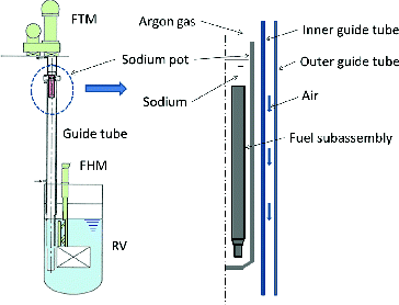
In JSFR, a spent fuel is discharged out of the core after 17 days following the reactor shutdown and has about 22.4 kW of maximum decay heat rate. The EVTM is designed to take approximately 30 minutes/subassembly to carry the transfer pot from the RV to the EVST. In the normal operation, active cooling is not necessary, since the pot has enough heat capacity for the operation. From the safety point of view, a sufficient cooling capacity has to be provided in case of transportation malfunction. One of the severest conditions is the pot stoppage in the guide tube as shown in . The transfer pot has to be cooled indirectly by air flowing outside the guide tube. To evaluate cooling capacity of the transfer pot, a mockup pot has been fabricated and heat transfer experiments have been conducted on the mockup pot.
2. Transfer pot design
Design conditions to the transfer pot are as follows:
refueling 17 days after shutdown,
decay heat of 22.4 kW per subassembly,
two core component positions in a transfer pot,
dimensions of the pot are consistent with the a compact RV and the core upper internal structure, and
sufficient heat transfer performance to maintain fuel cladding temperature below limitation (630 °C in a short term and 600 °C in a long term) in case of transportation malfunction.
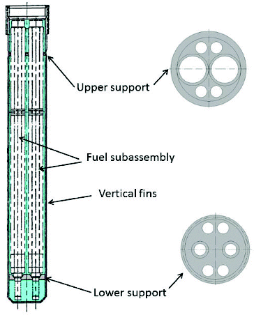
A sketch of the transfer pot is shown in [Citation2]. The pot is able to accommodate two core components and the pot dimensions are consistent with/applicable to the compact RV. The pot has vertical fins with chromium carbide coating on the outer surface in order to enhance thermal radiation.
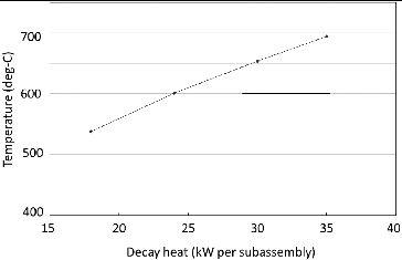
Heat removal capacity of the transfer pot with two FAs was preliminarily analyzed and shows the relation between the maximum temperature and decay heat of one spent FA [Citation3]. The maximum temperature of the spent FA with 23 kW of decay heat is less than 600 °C, which is defined as the temperature limit for the fuel integrity in a long term. Nevertheless, it is important to confirm that the transfer pot has a sufficient heat transfer capacity with a validated analytical model. The heat transfer mechanism is composed of sodium natural convection in the pot, thermal radiation from the pot to the guide tube, and forced convection of air outside the guide tube. In the refueling operation, the pot is carried by the EVTM between the RV and EVST in argon gas atmosphere. In the RV and EVST, the pot is immersed into sodium and the outer surface of the pot is wetted by sodium which might reduce thermal radiation. Therefore, cooling performance of the pot after sodium immersion has to be experimentally confirmed. In this study, developmental works are carried out in the following four items:
fabrication test on fin machining and coating process,
thermal emissivity measurement on coating specimen after sodium immersion,
cooling performance test on a mockup pot after sodium immersion, and
development of design tools for pot performance evaluation.
3. Mockup pot fabrication
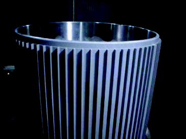
To evaluate the effect of fin configuration and coating conditions on fabrication performances, partial fabrication tests with full-scale fin height and pitch were conducted as shown in . Fins were fabricated by machining and coating was processed by high velocity oxygen fuel thermal spray or detonation with coating gun. As for the fin configuration, taking into account heat transfer analysis and coating gun accessibility into consideration, test samples varying fin pitches were fabricated. Chromium carbide coatings were selected based on the development experience of the Monju transfer pot. For coating probes, high velocity oxygen fuel thermal spray process and detonation process were compared using finned test samples.
As a result of the tests, fin machining had no technical issues for all fin pitch, and the high velocity oxygen fuel thermal spray process was selected because it was found to be more suitable for coating on the rather complicated-shaped surface such as fin than the detonation process. For the fin configuration, the results showed that fin pitch did not affect the coating process.
The heat transfer mechanism is characterized by a combination of sodium natural convection in the pot, thermal radiation from the pot to the guide tube, and forced convection air cooling outside the guide tube. Among those factors, the thermal radiation from the transfer pot surface to the guide tube dominates the total heat transfer. Additionally, the outer surface of the pot is wetted by sodium which may make the thermal radiation from the pot lower.
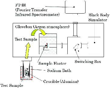
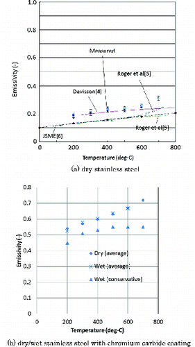
Emissivities of coated samples and coated samples wetted by sodium have been measured. The test apparatus is shown in . Samples of the coated metals with chromium carbide had been immersed in a sodium pot of 200 °C for 5 hours and discharged from the sodium pot for emissivity measurement. During emissivity measurement, temperatures of the samples were controlled by a heater, and then the thermal emissivities of the samples were measured optically by infrared spectrophotometer comparing the energy with blackbody furnace with emissivity higher than 0.99 in argon gas atmosphere. shows the measured thermal emissivity of 316 stainless steel and chromium carbide-coated specimen with temperatures ranging from 200 to 700 °C. The measured emissivity of the stainless steels is in good agreement with the reference data [Citation4–6] regarding the emissivity which is strongly dependent on the surface conditions. For coating samples, conservative plots take into account experimental errors of three-sigma showing higher value than the design value of 0.4.
4. Heat transfer performance test
4.1. Heat transfer experiment
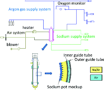
Heat transfer performance tests using a mockup transfer pot shown in have been carried out. The experimental apparatus, simulating the most severe condition of stoppage of the transfer pot in the guide tube on the way from the RV, is composed of the mockup transfer pot and guide tube, whose cross section including fin configurations is full-scale to confirm the effect of fin and coating performance in actual condition. A schematic flow diagram of the experimental apparatus is shown in . Side walls of the test pot which accommodate the mockup transfer pot are doubled and called “inner guide tube” and “outer guide tube”, respectively. And the annulus part can be cooled by circulated air. The test pot is connected to the sodium and argon gas lines providing sodium charge and drain to the inner annulus section between the mockup transfer pot and the guide tube to simulate immersion of the transfer pot in sodium. Heat of FAs were simulated by 36 electric heaters, placed inside the mockup transfer pot, whose heating length is 2000 mm to provide a uniform temperature profile. Outer diameter and thickness of the mockup transfer pot is 610 and 15 mm, respectively. Height, width, pitch, and number of the vertical fins on the mockup pot are 10, 3, 17.4 mm, and 110, respectively. The aguide tube has inner and outer walls. For the inner guide tube, outer diameter and thickness are 720 and 10 mm, respectively. For the outer guide tube, outer diameter and thickness are 966 and 98 mm, respectively. In addition to the pot outer surface, the inner surface of the inner guide tube is also coated with chromium carbide. Cooling air is introduced in the annulus section of the guide tube to simulate the indirect cooling. Flow rate of the cooling air is 20 m3/min-normal and inlet temperature is 50 °C.
For temperature monitoring, 140 thermocouples are located on the mockup pot surface. In the heated region, five monitoring sections for each 400-mm height are considered and each section has four thermocouples for each 90° on the inside wall of the mockup pot, the outside wall of the inner guide tube, and the outside wall of the outer guide tube (total 60 thermocouples). The thermocouples inside the mockup pot are welded on the wall with a cover preventing thermal irradiation from the heater. The thermocouples on the outside of the inner guide tube are located with 5-mm distance from the wall to measure temperature of the wall surface air. However, two thermocouples at the center of the heated region are located in the machined hole on the wall. The thermocouples on the outer guide tube are welded on the wall surface.
The heat transfer tests were conducted as follows: purified sodium at 250 °C was charged into the annulus section between the mockup transfer pot and guide tube, the sodium at 250 °C was maintained in the test section for at least 5 hours before sodium drain, and the pot temperature was raised by electric heaters inside the pot and the guide tube outside was cooled by air flowing between inner and outer walls of the guide tube. As for sodium introduction to the test pot, two methods, suction charge in vacuum and gravity charge, were conducted, but the difference in heat transfer performance was very small.
As a first step of the heat transfer performance tests prior to sodium supply to the test, the contribution of natural convection to heat transfer from the pot to the guide tube has been evaluated by comparing the heat transfer performance between two runs: one is at atmospheric pressure and the other is in vacuum. The test results indicate that thermal radiation dominates the heat transfer between the pot and the guide tube.
Heat transfer performance tests using sodium have been carried out to demonstrate the cooling performance of the proposed transfer pot. Test conditions are summarized in three cases from the standpoint of whether the coating is wet with sodium or dry as shown in .
Table 1. Conditions of heat transfer performance test.
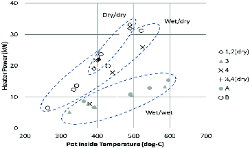
Results of the cooling performance tests of the mockup pot are summarized in . The numbers 1–4 and A and B show case numbers. The cases 1 and 2 are completely dry case before sodium charge. The cases 3, 4, A, and B start with the wet/wet condition and conditions are changed to dry/dry or dry/wet after experimental procedures. Relation of measured heater power and pot surface temperature is plotted and those data are categorized based on the surface conditions of the mockup pot and guide tube. Results of the heat transfer performance test and evaluated emissivities are summarized in . The emissivities in show calculated values which are roughly evaluated by a developed numerical method based on measured temperature and thermal conditions. In the plotted conditions in , the experimental conditions were maintained until the temperature reached steady state. The analysis method is described in the next subsection. For the case of “dry/dry”, the heat transfer performance is expected to be higher than required, because measured thermal emissivity of pot and guide tube of 0.5 exceed design value of 0.4.
Table 2. Results of heat transfer performance test.
“Wet/dry” case is a situation similar to the actual transfer pot RV. In fact, the actual guide tube is not in contact with liquid sodium. In the test apparatus, sodium introduced into the test pot contacts both the mockup transfer pot and the guide tube. In the experiment, sodium on the test apparatus guide tube is removed by heating in vacuum in a preparation procedure. As the pot temperature becomes higher than 400 °C during heating, reduction of cooling performance was observed by the phenomenon of sodium evaporation from the pot followed by deposition on the guide tube. Before this phenomenon occurred, heat transfer performance was similar to that of “dry/dry”. After this phenomenon took place, thermal emissivity of guide tube was evaluated to be approximately 0.3, which is smaller than the design value, but general heat transfer performance is higher than design value because thermal emissivity of the pot side maintained under dry condition is higher than the design value.
On the other hand, for case “wet/wet”, where not only pot but also guide tube is in contact with sodium, emissivity of pot is evaluated to be 0.5 but that of guide tube is 0.1. Thermal emissivity of 0.1 is equivalent to that of clean liquid sodium in inert atmosphere. The surface of guide tube is supposed to be covered with liquid sodium. Although thermal emissivity of guide tube of 0.1 is not assumed for an actual RV environment, lower limit of thermal emissivity of guide tube should be confirmed regarding sodium deposition on the guide tube during power operation.
4.2. Numerical analysis
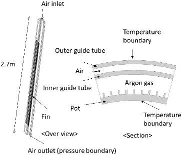
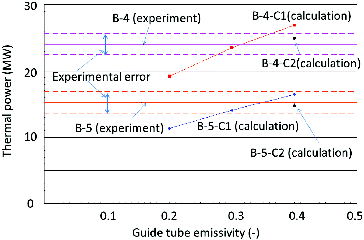
A three-dimensional thermal hydraulics analytical model has been developed and validated [Citation7]. Using the developed model, the thermal emissivities on the pot and guide tubes in the experimental conditions have been evaluated. Calculated conditions which were measured in the experiment are shown in . The heat removal values from the mockup transfer pot are evaluated based on the air flow rate and temperature difference between inlet and outlet. Computational geometry is shown in . It is a 1/12 sector partial model regarding as a symmetry in the circumferential direction of the experimental apparatus. Mesh configuration is hexagonal mesh with 0.23 million elements and 0.19 million nodes approximately. Temperature boundary conditions for the inner and the outer surfaces of the outer guide tube have set of the measured data in the experiment. In the experiment, the heated region in the pot has vertical fins with chromium carbide coating on the outer surface just as the transfer pot and the inner guide tube is also coated by chromium carbide. The annulus between the mockup pot and inner guide tube is filled with argon gas. The outer surface of the inner guide tube is cooled by forced air circulation supplied from a blower in the experimental apparatus. Heat transfer from the pot and inner guide tube should consist of thermal radiation and natural convection of argon gas. The thermal radiation is modeled by Monte Carlo method. In the annulus between the inner and outer guide tube, forced air convection mainly dominates heat transfer. For the region, shear stress transport turbulence model implemented in CFX [8] has been used. Wall treatment is based on automatic non-slip wall treatment supported by the CFX code. Thermal emissivities on the pot and guide tube sides are assumed to be 0.4 for case C1 series. For case C2, measured emissivity of stainless samples with and without chromium carbide coating in is used for the heated and non-heated area on the pot side, respectively. For the inner guide tube, emissivity is handled as parameter regarding sodium accumulation on the inner guide tube. Calculated cooling capacities are shown in . Experimental results are shown in lines since emissivities in experimental conditions are unknown. The C1 cases (B-4-C1 and B-5-C1) seem to be in good agreement with the experimental results. However, the emissivity on the pot side could be recovered from sodium deposition and higher than 0.4 since temperature on the pot side is high enough. In C2 cases (B-4-C2 and B-5-C2), the pot side are treated as recovered surface and the emissivity on the inner guide tube is handled as parameter. From the C2 survey results, emissivity which meets experimental thermal power is selected. And the evaluated thermal emissivities on the inner guide tube are 0.32 and 0.35 for B-4 and B-5, respectively.
Table 3 Numerical analysis conditions.
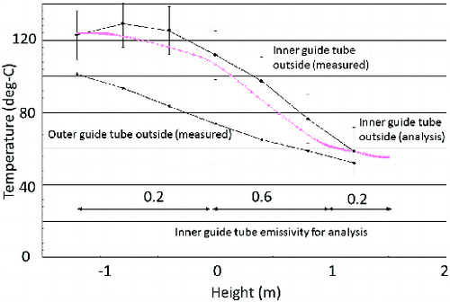
Case B-4-C3 has been conducted to analyzed effect of emissivity distribution on the inner guide tube, while the emissivity on the inner guide tube in cases C1 and C2 are treated as uniform. Mesh and boundary conditions except for emissivity are in the same conditions of cases C1 and C2. In case C3, emissivity of the inner guide tube is adjusted based on the measured temperature distribution. For the upper part of the heated part, emissivity of 0.6 is used based on the emissivity of coated samples. For the lower part of the heated part and non-heated part, emissivity of 0.2 is used regarding sodium accumulation or surface without coating. Calculated results with those emissivities are shown in . The measured and calculated temperature distribution shows good agreement. The measured and calculated heat removals of 24.0 and 24.6 kW, respectively, also show good agreement. The B-4-C3 calculation suggested that the sodium vapor mainly accumulated at the lower part of the inner guide tube.
4.3. Surface observation after heat transfer experiment
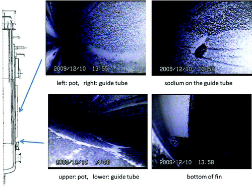
After the heat transfer experiment, surfaces of the mockup pot and the inner guide tubes were observed. Before the surface observation, sodium was charged into the annulus between the mockup pot and inner guide and maintained at 250 °C for 4 hours. After the sodium drain, air cooling of 20 m3/min at 50 °C was started and the heater temperature was controlled to 400 °C for 4 hours and 550 °C for 12 hours. When the heater temperature is 550 °C, the pot surface temperature is in the range from 450 to 500 °C and the heater power is 12 kW approximately. Photographs of observed surfaces are shown in . On the pot side, the chromium carbide coating surface could be observed, while the guide tube surface was covered with metallic sodium. The surface observation shows clear differences between pot and guide tube sides. The results confirm that the reduction of cooling performance in the mockup pot experiment was mainly caused by sodium accumulation on the guide tube side.
4.4. Sodium deposition experiment
Sodium deposition due to sodium immerse and vapor accumulation has been confirmed by fundamental experiments. In the sodium immerse experiment, chromium carbide coating samples were immersed to the sodium pot and sodium deposition was measured. Similar to the mockup pot experiment conditions, the experimental processes were as follows:
sample preheating in argon gas circumstance for 2 hours,
sodium immerse at argon gas pressure approximately 100 Pa,
sodium immerse at 250 °C for 5 hours, and
sample discharge from sodium at atmosphere pressure.
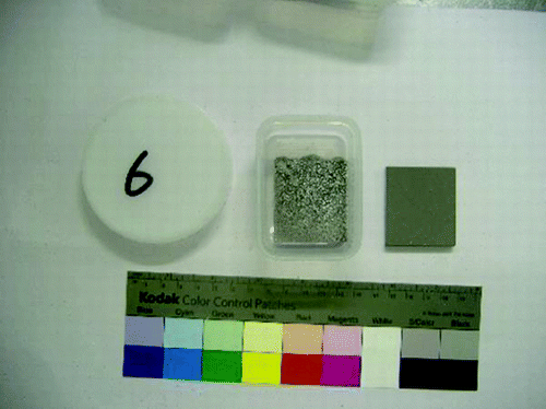
The discharged sample is shown in . The sample is clearly covered with metallic sodium. The experimental result shows that chromium carbide coating could be covered with metallic sodium after sodium immersion.
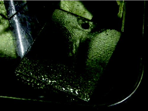
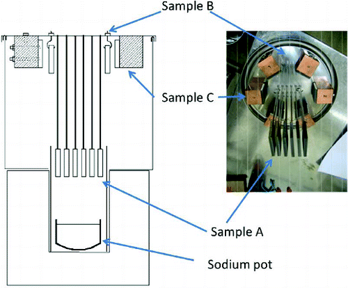
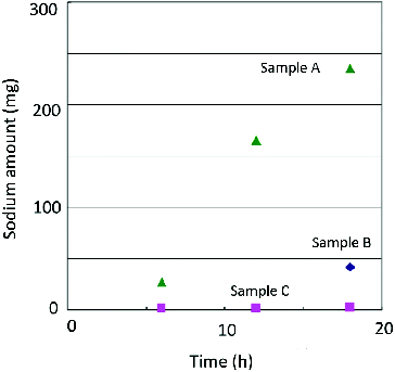
Sodium vapor accumulation on the inner tube side has been confirmed by a fundamental experiment in a globe box. The experimental apparatus is shown in . Sodium vapor was provided from a heated pot at the bottom. Samples are stainless steel plates with chromium carbide coating. Sample A is located just above the sodium pot. Samples B and C are located at the top of experimental apparatus to discover effect of distance from vapor source. The sample C contact with copper block to maintain temperature lower than that of the sample B. The samples were discharged after sodium vapor exposure and amount of sodium was measured by inductively coupled plasma atomic emission spectrometry (ICP-AES). Relation between duration of sodium vapor exposure and amount of accumulated sodium vapor is shown in . Sodium accumulation on the sample A is basically different from those of samples B and C. The sodium amount on the sample A increased with exposure time while sodium on the samples B and C were maintained to be much smaller. A photograph of one of samples A after 18 hours sodium vapor exposition is shown in . Temperature of the sample C was measured to be approximately 90 °C. The results show that temperature dependency of sodium vapor accumulation is low. Results suggest that sodium vapor becomes sodium mist just above the pot and sodium mist is accumulated on the first contact surface regardless of surface temperature.
5. Conclusions
A spent fuel transfer pot for ex-vessel fuel handling which can contain two FAs simultaneously and whose size is applicable to compact RV has been developed for JSFR. The fabrication tests show that fin machining has no technical issues, and the high velocity oxygen fuel thermal process is selected for chromium carbide coating process. The heat transfer test using the mockup transfer pot show that thermal radiation strongly depends on sodium accumulation on the pot and guide tube surfaces. Emissivities of various surface conditions are measured and categorized to develop design tools of the fuel transfer pot. Numerical analysis with realistic emissivity distribution is in good agreement with measured temperature distribution. Surface observation of the mockup transfer pot and fundamental tests in the globe box also show sodium accumulation on the chromium carbide coating surfaces. Above experimental results are used for the development of design evaluation tools of the fuel transfer pot.
Acknowledgements
The present study includes the results of “Development of Fuel Handling System” entrusted to the Japan Atomic Power Company (JAPC) by the Ministry of Education, Culture, Sports, Science and Technology of JAPAN (MEXT).
References
- Uto N, Sakai T, Mihara T, Toda M, Kotake S, Aoto K. Conceptual design for Japan sodium-cooled fast reactor (1): Current status for system design for JSFR. Proc. ICAPP2009; 9298; 2009 May; Tokyo, Japan.
- Chikazawa Y, Usui S, Konomura M, Ikeda H. Design study on fuel handling system in a sodium cooled reactor – study in FY2004 JAEA-research 2006-032; 2006. Japanese.
- Usui S, Mihara T, Obara H, Kotake S. Development of advanced loop-type fast reactor in Japan. Proc. ICAPP2008; 8223; 2008 June; Anaheim, CA, USA.
- Davisson C, Weeks JR Jr. The relation between the total thermal emissive power of a metal and its electrical resistivity. J Opt Soc Am. 1924;8:581–605.
- Roger CR, Yen SH, Ramanathan KG. Temperature variation of total hemispherical emissivity of stainless steel AISI 304. J Opt Soc Am. 1979;69:1384–1390.
- Japan Society of Mechanical Engineering. JSME data book: heat transfer. 4th ed. Japan: JSME; 1986.
- Chikazawa Y, Hirata S, Obata H. Development of design evaluation tools for the JSFR fuel transfer pot. Nucl Eng Des.
- ANSYS CFX User Manual. USA: ANSYS; 2006, ANSYS-CFX-10.

