Abstract
In order to eliminate the energetic potential in the case of postulated core-disruptive accidents (CDAs) of sodium-cooled fast reactors, introduction of a fuel subassembly with an inner-duct structure (FAIDUS) has been considered. Recently, a design option of FAIDUS which leads molten fuel to upward discharge has been considered as the reference core design of the Japan Sodium-Cooled Fast Reactor (JSFR). In this study, a series of experiments which consisted of three out-of-pile tests and one in-pile test were conducted to obtain experimental knowledge of the upward discharge of molten fuel. Experimental data which showed a sequence of upward fuel discharge and effects of initial pressure conditions on upward discharge were obtained through the out-of-pile and in-pile test. Preliminary extrapolation of the present results to the supposed condition in the early phase of the CDA in the JSFR design suggests that the sufficient upward flow rate of molten fuel is expected to prevent the core melting from progressing beyond the fuel subassembly scale and that the upward discharge option will be effective in eliminating the energetic potential.
1. Introduction
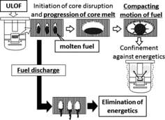
One of the major concerns in the safety of sodium-cooled fast reactors (SFRs) is the possibility of recriticality and resultant energetic potential in case of postulated core-disruptive accidents (CDAs) because an SFR core is not designed in the most reactive configuration and may exceed prompt criticality under hypothetical degraded-core conditions. The typical initiator leading to the CDA in SFRs is the unprotected loss of flow (ULOF) in which the failure of the reactor scram is assumed in case of trips of all the primary-coolant pumps [Citation1–3]. The ULOF brings sodium boiling in the core region and this boiling inserts the positive reactivity. If the core reactivity does not exceed the prompt criticality significantly, the core will melt gradually. However, as illustrated in , the progression of core melting and the formation of a large-scale molten-fuel pool in the core region is one of the factors leading to energetics, and, therefore, discharge of molten fuel from the core region in the early phase of the CDA is effective to eliminate such energetic potential.
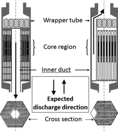
A number of designs have been considered to realize the fuel discharge in the early phase of the CDA, and a fuel subassembly called “FAIDUS” (Fuel Assembly with Inner-Duct Structure), which is shown schematically in , has been considered as one of the most promising design measures toward commercialization of an SFR [Citation3–9].
A design option of FAIDUS shown in the left of has an orifice at the top end of the inner duct whereas the bottom end is open. If the ULOF occurs, molten fuel will melt the inner duct and will discharge from the core region to the inlet coolant plenum. Here, we call this design option “the downward discharge option”. Concerning the downward discharge option, a series of demonstrative experiments were already conducted under the “EAGLE” (Experimental Acquisition of Generalized Logic to Eliminate recriticalities) joint-research program, in which safety research facilities in the National Nuclear Center of the Republic of Kazakhstan (NNC/RK) were utilized [Citation10]. The program successfully obtained experimental evidence on the sequence of fuel discharge [Citation11]. Although the downward design option has reliability for molten-fuel discharge since gravity force is available, further studies are required to investigate thermal effects, namely thermal impacts by discharged molten fuel on the core support structures, long-term coolability of discharged fuel, since the total amount of the fuel in the core region will relocate downward. On the other hand, a design option of FAIDUS which is adopted in the Japan Sodium-Cooled Fast Reactor (JSFR) [Citation6,Citation12] as its reference core design will mitigate such thermal effects, since this option is designed to discharge molten fuel toward the upper plenum region by setting the open and closed ends at the top and bottom ends of the inner duct as shown in the right of . Here, we call this design option “the upward discharge option”.
Qualitatively, it is supposed that the ability for molten-fuel discharge of the upward discharge option is inferior to that of the downward discharge option since molten fuel is a high-density material and it discharges against the gravity. Some basic experiments using simulant materials were conducted to investigate a mechanism of the upward discharge of a high-density melt in detail [Citation13,14]. In order to strengthen experimental evidence on upward discharge under the CDA condition, it is encouraged to perform integrated experiments using high-temperature materials (uranium dioxide or an oxide material) and sodium. Therefore, in the present study, experiments which consist of a series of out-of-pile tests and one in-pile test were performed in order to obtain experimental knowledge of the upward discharge of molten fuel. Furthermore, the effectiveness of the upward discharge option for reducing energetic potential is considered in this paper.
2. Experimental program and procedures
2.1. Out-of-pile test
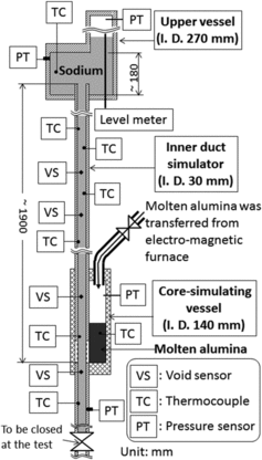
The role of out-of-pile tests is to obtain data for understanding upward discharge phenomena and to investigate the effect of pressure differences between the core and the upper sodium plenum regions on upward discharge behavior. A schematic diagram of the experimental device for the out-of-pile series tests is shown in . The test device consists of a core-simulating vessel, an inner-duct simulator and an upper vessel, which simulate a degrading core region, the inner duct and the uppercoolant plenum, respectively. In tests, a core simulant is heated and melted by induction heating in the electromagnetic furnace, and the molten core state is generated by pouring molten-core simulant into the core-simulating vessel. Based on knowledge obtained by an out-of-pile test series for the investigation of downward discharge [Citation15] and some in-pile test [Citation11,16,17] a part of the discharge duct which is located below the surface of the molten core pool is made up of aluminum instead of steel so as to achieve rapid failure of the discharge duct without sodium boiling, which is considered as a typical CDA sequence [Citation3].
Same as the out-of-pile test series for the investigation of downward discharge [Citation15], alumina was selected as a fuel simulant considering heat-transfer characteristics both to sodium and to the channel wall since these heat-transfer characteristics affect the heat loss of molten material discharging through the inner duct. A sequence of melt discharge phenomena and related sodium movement are mainly measured by thermocouples, void sensors and pressure sensors. Relocated masses of molten alumina inside the test device are quantified by dismantling the test device. The inner diameter of the inner-duct simulator is 30 mm and its length from the bottom of the core-simulating vessel to the top end is approximately 1900 mm. The bottom of the inner-duct simulator is closed after the sodium is supplied into the experimental device. The initial conditions for out-of-pile tests presented in this paper are listed in . The out-of-pile tests were performed using experimental facilities in NNC/RK.
Table 1. Initial conditions for out-of-pile tests.
2.2. In-pile test
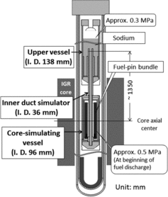
The role of the in-pile test is to confirm knowledge of upward discharge phenomena obtained through the out-of-pile tests using real core materials. A schematic diagram of the experimental device for the in-pile test is shown in . The basic components of the test device for the in-pile test are common with those for the out-of-pile test, namely consisting of two vessels and a duct which simulate the degrading core region, the upper coolant plenum and the inner duct, respectively.
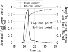
The inner diameter of the inner-duct simulator is 36 mm and its length from the axial center of the pin bundle to the top end is approximately 1350 mm, which is consistent with the FAIDUS design for the upward discharge option because the in-pile test is demonstrative one using the real core materials. The fuel-pin bundle made of uranium dioxide and steel cladding is loaded in the core-simulating vessel, and the test device is installed in the central experimental channel of IGR (impulse graphite reactor) of NNC/RK. The masses of uranium dioxide and steel are approximately 8 and 2 kg, respectively. Energy insertion into uranium dioxide of the pin bundle by high neutron flux from IGR melts the fuel-pin bundle rapidly and generates the molten-core state. The initial sodium temperature of the inner duct is approximately 720 K at the core axial center of IGR and that of the upper vessel is approximately 620 K. Same as the out-of-pile tests, thermocouples, void sensors and pressure sensors are used mainly to investigate a sequence of melt discharge phenomena and related sodium movement. The realized energy insertion history for the fuel-pin bundle in the test is shown in .
3. Results and discussions
3.1. Results of out-of-pile tests
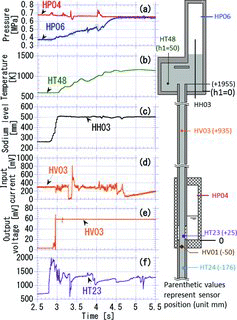
Upward melt discharge was observed in all the tests shown in , and phenomenological features were the same in these experiments. Here, we use the results of test 3 to explain the typical behavior of the upward melt discharge. The obtained data are presented in with the layout of sensors. (a) shows pressure transitions at the cover gas regions of core-simulating and upper vessels, (b) and (c) show, respectively, transitions of temperature and level of sodium in the upper vessel, (d) and (e) show, respectively, transitions of output voltage and input current of a probe-type void sensor called “chen-type” [Citation18] and (f) shows a temperature transition of sodium in the inner-duct simulator. In , a base point to define the axial locations of sensors in the inner-duct simulator is set at the melt bottom in the core-simulating vessel and minus notations mean that the measurement points are located below the melt bottom. Concerning the upper vessel, the base point of thermocouples and the level meter is set at its bottom. A base time of is defined when an operation to pour molten alumina into the core-simulating vessel started.
At approximately 2.8 s, the signal of thermocouple HT23 increased sharply, which suggests that molten alumina penetrated into the inner-duct simulator. The output voltage of the void-sensor HV03 began to increase at 2.9 s, which means the detection of void in the inner-duct simulator initially filled with sodium, namely, liquid sodium was discharged by sodium vapor development, which is supposed to be generated from heat-transfer between molten alumina and sodium. The sodium vapor development inside the inner-duct simulator was also confirmed by a continuous increase of the sodium level in the upper vessel. The reason for the steady state of the sodium level after 3 s is that the sodium level exceeded the top limit of the level meter. At 2.95 s, the input current of the void sensor HV03 began to change. Since the input current of the void sensor was controlled to maintain a constant value and the used void sensor was the probe-type one, the most likely cause of the current change was destruction of the void sensor by the arrival of massive molten alumina. At approximately 3.05 s, the signal of thermocouple HT48 increased gradually, which suggests that molten alumina discharged upward through the inner-duct simulator and began to accumulate at the bottom of the upper vessel. After approximately 4.2 s, the increase of the cover-gas pressure in the upper vessel (HP06) accelerated. Since there was a pressure difference between the core-simulating and upper vessels at the initiation of the test and the inner duct played a role of a connecting tube of the two vessels, the pressures of the two vessels changed to be at equilibrium after the failure of the inner duct. Therefore, it is reasonable to interpret that the cover gas in the core-simulating vessel discharged through the inner duct efficiently and this gas discharge accelerated the pressure increase for the upper vessel since the cross section of the inner duct became empty along its discharge direction. In other words, in the test section used for the out-of-pile tests, the termination of the molten-alumina discharge can be indicated by the pressure transition in the upper vessel. It should be noted that the temperature decrease shown by the thermocouple HT23 did not correspond to the termination of the molten-alumina discharge because this thermocouple was supposed to be destroyed around 2.9 s by direct contact with molten alumina.
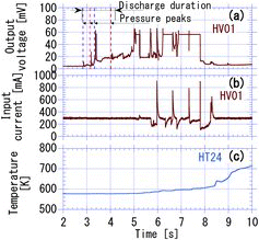
Next, we show the sensor responses in with the layout of sensors to consider the effect of phenomena in the downward section on the upward relocation of molten alumina. Both definition of the base position of sensors and definition of the base time are common with those in .
(a) and (b) shows, respectively, transitions of the output voltage and input current of the probe-type void sensor HV01, and (c) shows a temperature transition measured by the thermocouple HT24. During the upward discharge (from 2.8 to 4.2 s), the output voltage increased several times, which corresponds to the detection of the void in the lower part of the core-simulating vessel, and these output voltage increases were consistent with the increases of the cover-gas pressure in the core-simulating vessel (HP04 in (a)). Especially, around 3.3 s, there was a sharp increase of the output voltage of the void sensor, HV01, and the cover-gas pressure in the core-simulating vessel also increased. After this cover-gas pressure increase, the increase rate of the sodium temperature in the upper vessel was accelerated (see HT48 in (b)). From these data, one may say that the sodium vapor supplied from the lower part of the inner-duct simulator increased the cover-gas pressure in the core-simulating vessel, and this pressure increase accelerated the upward discharge of molten alumina. This role of the coolant located below the molten material in increasing the driving force of the upward discharge was pointed out in the some basic experiments using simulant materials [Citation13,14]. The input current of the void sensor HT01 kept a constant value until approximately 5.0 s, and the sodium temperature at the lower part of the inner-duct simulator began to increase at approximately 5.2 s. These data show that a significant penetration of molten alumina did not occur until the termination of upward discharge since the sodium vapor generated at the lower part of the inner-duct simulator expanded toward the open end (upward) which also brought molten alumina upward.
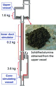
In order to obtain additional data for understanding discharge phenomena in detail and to quantify masses of discharged materials, post-test observations were performed by dismantling each experimental device. A mass distribution of solidified alumina after test 3 is presented in , schematically.
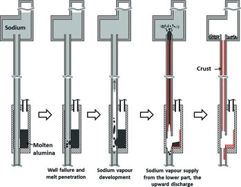
A crust was formed on the inner surface of the inner-duct simulator, which shows a massive discharge of molten alumina occupying the cross section of the discharge path. Solidified alumina obtained from the upper vessel was fragmented into small particles. This means that thermal interaction between discharged molten alumina and sodium took place in the upper vessel. On the other hand, solidified alumina remained in the core-simulating vessel was in the form of ingot. A solidified material composed of steel mainly was found in the lower part of the inner-duct simulator. The sequence of the upward discharge based on interpretation on transient data and post-test investigations is presented schematically in . The mass distributions of solidified alumina in all tests are summarized in .
Table 2. Summary of the experimental results.
3.2. Results of the in-pile test
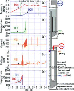
Transient data obtained in the in-pile test are presented in with the sensor layout. The base point to define the axial locations of sensors is the same level of the core axial center of IGR which was the same level as the fissile center of the fuel-pin bundle loaded in the core-simulating vessel. Minus notations in mean that the measurement points are located below the base point.
(e) shows temperature transients for the inner wall surface of the inner-duct simulator and sodium in it. It is shown that the heat transfer from the molten core materials to the duct wall began around 21.8 s, at which the average fuel specific energy exceeded the liquidus point as shown in , and the duct wall failed around 22.3 s which can be detected by sharp temperature increases both in the duct wall and sodium. Sodium temperature increased slightly until the duct wall failure, which means that the wall of the inner-duct simulator was heated adiabatically and the effect of sodium cooling on duct-wall failure was not remarkable. This behavior on wall failure is similar to that observed in the previous in-pile tests [Citation11,Citation16]. (d) shows an output voltage of the probe type void sensor that was located at the upper part of the core-simulating vessel. The output voltage increased sharply at 22.4 s, which corresponds to the detection of a coolant void in the inner-duct simulator. Since this coolant void was detected after the failure of the duct wall, it is supposed that sodium was vaporized by heat transfer from the molten-core material and the void region was developed by the expansion of sodium vapor. The input current of the void sensor shown in (c) became unstable at 22.47 s, which shows destruction of the probe by the arrival of molten fuel since the input current for the void sensor was controlled to maintain a constant value and the temperature of molten fuel was high enough to melt the void sensor made of steel. (b) shows a temperature transient at the bottom of the upper vessel. The temperature increased sharply at 22.6 s, which corresponds to the accumulation of discharged fuel (and/or steel). This temperature response supports the above interpretation on the input current of the void sensor. (a) shows the pressure transients of cover gases in the core-simulating vessel and the upper vessel, respectively. The cover-gas pressure of the core-simulating vessel increases constantly until the failure of the inner-duct simulator (at 22.3 s), since inert gas expands in accordance with the temperature increase of pin bundle. At 22.35 s, just after the onset of the wall failure, the increase rate of the cover-gas pressure in the core-simulating vessel changes. The most probable cause of this pressure increase rate changing is considered to be sodium vaporization which was also observed in out-of-pile tests. After approximately 23.8 s, the cover-gas pressure of the core-simulating vessel began to decrease continuously and this time was interpreted as the termination of the molten-fuel discharge since, same as the test sections used for the out-of-pile tests, the inner duct played a role of the connecting tube between the core-simulating and the upper vessels, and, therefore, the cover gas of the core-simulating vessel could have discharged through the inner duct efficiently if the inner duct had become empty. It should be noted that investigations on the test device after the experiment found the plugging formation inside the tube for pressure measurement in the upper vessel (DD5). One can suppose that fuel discharge into the upper vessel ejected sodium upward and it penetrated and plugged inside the tube for pressure measurement. Therefore, the pressure of the upper vessel had been constant at 0.38 MPa after 22.8 s (see DD5 in Figure 10(a)).
The mass distribution of solidified fuel and steel inside the test device was estimated in post-test observations. By removal of fuel and steel mixture from the upper vessel, the mass of upward discharge from the core-simulating region was estimated to be approximately 9.1 kg. The other places where the solidified fuel and steel mixture existed were the lower and upper parts of the core-simulating vessel. It seems reasonable to suppose that sodium vaporization just after the onset of the inner-duct wall failure dispersed a portion of molten fuel–steel mixture towards the upper part of the core-simulating vessel. The sequence of the upward fuel discharge based on the above interpretation on transient data and post-test investigations is common with that of out-of-pile tests presented in .
3.3. Discussion
It was shown through three out-of-pile tests and one in-pile test that the molten fuel can be discharged upward against the gravity driven by the initial pressure difference between the core and the upper plenum regions and sodium vapor expansion. However, we should not overlook that the role of the inner duct is to prevent progression of core melting toward the formation of a large-scale molten-fuel pool in the core region, which has a potential leading to energetics. Since the wrapper tube is designed to be two or three times thicker than the inner duct [Citation8], it takes a different amount of time to fail the wrapper tube and the inner duct by the heat transfer from the molten-core materials. Therefore, if the molten fuel in the fuel subassembly discharges through the inter duct before the failure of the wrapper tube, the formation of a large-scale molten-fuel pool will be prevented since the wrapper tube separates the molten-fuel in each fuel subassembly. Here, we introduce a criterion named the required flow rate for molten fuel to evaluate the effectiveness of the upward discharge option for prevention of core-melting progression. The required flow rate for molten fuel through the inner duct, Qf, liq, is simply given by
(1) where mf, liq and ρf, liq, respectively, are the mass and density of molten fuel, and Δtfail is the time difference between failures of the wrapper tube and the inner duct.
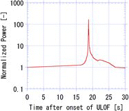
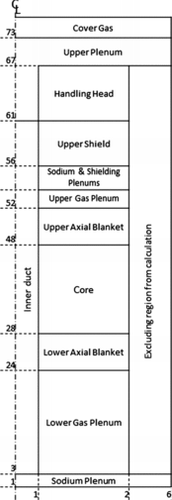
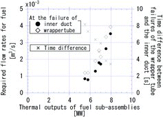
Since both the mass of molten fuel and the time difference depend on thermal outputs of the fuel subassemblies in the normal operation, a power transient and a heat transfer from the molten core to the inner duct, evaluations on a core design using computer codes are required to define the required flow rate. In this paper, the required flow rates for the core design of the JSFR are evaluated. The event progression in CDAs of SFR is usually analyzed by the combination of the SAS4A [Citation19,20] and the SIMMER-III codes [Citation21,22]. After the ULOF onset, the accident progresses under the competition of positive and negative reactivity insertions. The main contributor of positive reactivity is coolant void reactivity, and negative reactivity would be provided by a Doppler effect, one-dimensional fuel axial expansion and relocation inside a fuel subassembly driven by fission gas. The SAS4A code is designed to analyze the initial accident progression mechanically taking the above positive and negative reactivity insertions into account. However, the SAS4A code is not designed to model FAIDUS, and, therefore, this code cannot evaluate a sequence of molten-core formation and the heat-transfer between molten-core materials and the inner duct. On the other hand, the SIMMER-III code can model FAIDUS and analyze the above sequence since this code is designed to analyze the progression of core melting and to have flexibility for modeling geometrical configuration. However, the SIMMER code cannot accurately evaluate reactivity changes by the above positive and negative reactivity insertions during the initial accident progression. In order to compensate disadvantages of two codes, a procedure is adopted in the present study in which the power transient during the initial accident progression is evaluated by the SAS4A code and the sequence of molten-core formation and temperature increases of the inner duct and the wrapper tube due to the heat-transfer from molten-core materials are evaluated by the SIMMER-III code using the power transient provided by SAS4A evaluation. Although the above procedure is preliminary, it is effective to evaluate the required flow rate since the amount of molten fuel is proportional to an integrated energy inserted in the fuel and the time difference between the failures of the wrapper tube and the inner duct can be evaluated based on the heat-transfer characteristics of fuel–steel mixture observed in the experiments [Citation16,17]. The power transient used in this calculation is shown in , which is an evaluated result for the core design of the JSFR [Citation23]. In the present calculation, the core was divided into eight regions based on their thermal outputs during a normal full-power operation, and eight subassemblies were selected to represent each region. All the representative subassemblies were commonly modeled by a two-dimensional configuration as shown in .
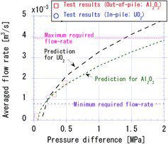
In order to evaluate the required flow rates, the following two definitions were used for the mass of molten fuel, mf, liq, in Equation (Equation1(1) ): one is the mass of molten fuel at the failure of the inner duct and the other is that at the failure of the wrapper tube. The evaluated results for the JSFR are plotted in . Since the amount of molten fuel increases and the time difference between failures of the wrapper tube and the inner duct decreases as thermal outputs of the fuel subassemblies increase, the required flow rate increases sharply in proportion to thermal outputs of the fuel subassemblies. The results of seven subassemblies are plotted in , and the result of one subassembly whose thermal output was the lowest among the selected subassemblies is not presented since the fuel did not melt during calculations. It should be noted that the amount of molten-core materials decreases after the onset of their discharge through the inner duct, and this discharge significantly reduces the thermal load to the wrapper tube. We neglected this reduction effect of the thermal load on the wrapper tube in the current evaluation to obtain the time differenceΔtfail, and, therefore, the upper values of required flow rates shown in would be the over-estimated values. It should be noted that there are several subassemblies whose thermal outputs at the normal full-power operation exceed 8 MW; however, such subassemblies are dispersed in the core region. Therefore, the formation of a molten-fuel pool will be eliminated virtually if the flow rate of approximately 4.0×10⁻³ m3/s is achieved, namely, that flow rate is a bounding one of the JSFR to prevent the formation of a large-scale molten-fuel pool.
Figure 13. Required flow rates for molten fuel through the inner duct and the time difference between failures of the wrapper tube and the inner duct.
Next, we evaluate the averaged melt flow rate based on data obtained through the out-of-pile and in-pile tests, which can be given by
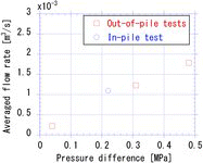
(2) where mm, d is the mass of the melt discharge from the core-simulating vessel, and ρm and Δtd, respectively, are the density of melt and the duration of melt discharge in each test. A ratio of flow areas, ASA/At, where ASA is the flow area of the inner duct of FAIDUS and At is that of the ducts used in the out-of-pile and in-pile tests, is necessary to directly compare the test results with the required flow rates shown in . The evaluated results are summarized in .
It is shown that the melt flow rate increases in accordance with the increase of the pressure difference between the core-simulating and upper vessels. The conditions for pressure differences in these tests were set lower than those expected in CDA conditions since it was supposed that melt discharge under the high-pressure difference would be too rapid to investigate a sequence of discharge. In the present calculations, the pressure difference between the core and the upper plenum regions was evaluated to be more than 1.5 MPa since fission gas was released from molten fuel and tight blockages were formed near the axial top and bottom of the pin bundle. This pressurization mechanism is consistent with experimental results [Citation24].
In order to compare the test results with the required flow rate of molten fuel shown in , the averaged flow rates for the upward discharge tests shown in should be extrapolated to the pressure conditions supposed in the CDA, taking into account the pressure loss inside the duct given by
(3) where l and Dh, respectively, are the length and the hydraulic diameter of the duct, and, ρm and vm, respectively, are the density and the average velocity of the discharging melt. Concerning the friction factor, λ, we used the following Blasius formula [Citation25] given by a function of the Reynolds number, Re, assuming that the flow condition of the main discharge stage was steady flow:
(4) The predicted average flow rates for the upward discharge of molten alumina and fuel are, respectively, shown in with the test results.
It can be confirmed that the evaluated values for both molten alumina and fuel are consistent with both out-of-pile and in-pile test results, and, therefore, these evaluated average flow rates can be extrapolated to pressure conditions supposed in the CDA. The extrapolated results for the in-pile test show that the required flow rates through the inner duct, which is approximately 4.0 × 10⁻³ m3/s in maximum as shown in , will be achieved even though the molten fuel discharges against the gravity if the pressure difference between the core and the upper sodium plenum exceeds approximately 1.4 MPa, which is lower than the evaluated pressure difference (1.5 MPa). The above prediction for upward fuel discharge under the supposed CDA pressure conditions supports the effectiveness of the upward discharge option although the evaluation method is preliminary. In order to confirm the present predictions, the following studies will be effective: First, validations of the SIMMER-III code using the present test results, and then, evaluations using the validated code, in which disruption and melting of fuel pins, heat transfer from molten core to the inner duct and the wrapper tube, upward discharge of molten core through the inner duct and reactivity change coupled with these sequence will be evaluated. In addition to the above evaluations on the fuel discharge through the inner duct, comprehensive evaluations which address the falling of upper discharged fuel, collapse of upper core structures and so on are required to define the amount of discharged fuel sufficient to terminate the CDA in the sub-critical condition since those events insert positive reactivates [Citation23]. Furthermore, the effect of pressurization in the core region on the effectiveness of the upward discharge option should be investigated in detail taking into account possible gas escape through the blockage-like core-materials accumulations around the top and bottom of the fissile region on one hand and the amount of initial fission gas accumulated in fuel pellets on the other hand.
4. Conclusions
A series of experimental studies consisting of the out-of-pile tests and the in-pile test were conducted in order to obtain experimental knowledge of the upward discharge of molten fuel. The following knowledge was obtained through the present experimental study:
A sequence of upward discharge phenomena was confirmed, which consist of molten-core pool formation, inner-duct failure, sodium vaporization and void development toward the discharge direction due to the initial heat transfer from melt to sodium and upward massive melt discharge through the voided duct.
Sodium vaporization after the inner-duct failure can increase the upward driving force and this sodium vaporization occurred mainly at the lower part of the inner duct.
The flow rate of upward melt discharge increased in accordance with the increase of the initial pressure difference between the core-simulating and upper vessels.
Preliminary extrapolation of the present results to the supposed condition in the early phase of the CDA in the JSFR design suggests that the sufficient upward flow rate of molten fuel was expected to prevent the core melting from progressing beyond the fuel subassembly scale. The present study suggests that the introduction of the upward discharge duct into the fuel subassembly will be effective for eliminating the energetic potential.
Acknowledgements
The authors would like to acknowledge invaluable contributions that the NNC/RK-team made to this study. They gratefully acknowledge helpful discussion with Professor M. Saito of Tokyo Institute of Technology and members of EAGLE WG on several points in this study. The authors would like to express their gratitude to Messrs. M. Sugaya, S. Hosono and T. Kondo of NESI Inc., for their important technical contributions. Thanks are due to Dr T Suzuki for helpful comments on a draft of this paper.
References
- Theofanous TG, Bell CR. An assessment of Clinch River Breeder Reactor core disruptive accident energetics. Nucl Sci Eng. 1986;93:215–228.
- Tobita Y, Morita K, Kawada K, Niwa H, Nonaka N. Evaluation of CDA energetics in the prototype LMFBR with latest knowledge and tools. Proceedings ICONE-7; 1999 April 19–23; Tokyo (Japan). [CD-ROM].
- Sato I, Tobita Y, Konishi K, Kamiyama K, Toyooka J, Nakai R, Kubo S, Kotake S, Koyama K, Vassiliev Y, Vurim A, Zuev V, Kolodeshnikov A. Safety strategy of JSFR eliminating severe recriticality events and establishing in-vessel retention in the core disruptive accident. J Nucl Sci Technol. 2011;48:556–566.
- Endo H, Kubo S, Kotake S, Sato I, Kondo Sa, Niwa H, Koyama K. Elimination of recriticality potential for the self-consistent nuclear energy system. Program Nucl Energy. 2002;40:577–586.
- Niwa H, Tobita Y, Kubo S, Sato I. Safety implications of the EAGLE experimental results for the fact project. International Conference Nuclear Power of Republic Kazakhstan; 2007 Sept. 3–5; Kurchatov (Kazakhstan).
- Kotake S, Sakamoto Y, Mihara T, Kubo S, Uto N, Kamishima Y, Aoto K, Toda M. Development of advanced loop-type fast reactor in Japan. Nucl Technol. 2010;170:133–147.
- Tobita Y, Yamano H, Sato I. Analytical study on elimination of severe recriticalities in large scale LMFBRs with enhancement of fuel discharge. Nucl Eng Des. 2008;238:57–65.
- Mizuno T, Niwa H. Advanced MOX core design study of sodium-cooled reactors in current feasibility Study on commercialized fast reactor cycle systems in Japan. Nucl Technol. 2004;146:155–163.
- Ninokata H, Kamide H. Thermal hydraulics of sodium-cooled fast reactors: key design and safety issues and highlights. Nucl Technol. 2013;181:11–23.
- Konishi K, Kubo S, Koyama K, Kamiyama K, Toyooka J, Sato I, Kotake S, Vurim AD, Zuyev VA, Pakhnits AV, Gaidaichuk VA, Kolodeshnikov AA, Vassiliev YS. Overview on the EAGLE experimental program aiming at resolution of the re-criticality issue for the fast reactors. International Conference Nuclear Power of Republic Kazakhstan; 2007 Sept. 3–5; Kurchatov (Kazakhstan).
- Konishi K, Kubo S, Sato I, Koyama K, Toyooka J, Kamiyama K, Kotake S, Vurim AD, Gaidaichuk VA, Pakhnits AV, Vassiliev YS. The EAGLE project to eliminate the recriticality issue of fast reactors - progress and results of in-pile tests -. Proceedings of the NTHAS5; 2006 Nov. 26–29; Jeju (Korea). [CD-ROM].
- Hishida M, Kubo S, Konomura M, Toda M. Progress on the plant design concept of sodium-cooled fast reactor. J Nucl Sci Technol. 2007;44:303–308.
- Matsuba K, Isozaki M, Kamiyama K, Tobita Y. Experimental study on upward fuel discharge during core disruptive accident in JSFR: Results of an out-of-pile experiment with visual observation. Proceedings of ICONE19; 2011 May 16–19, Chiba (Japan). [CD-ROM].
- Matsuba K, Isozaki M, Kamiyama K, Tobita Y. Mechanism of upward fuel discharge during core disruptive accident in sodium-cooled fast reactors. J Eng Gas Turbine Power. 2013;135:032901.1–9.
- Kamiyama K, Saito M, Matsuba K, Isozaki M, Sato I, Konishi K, Zuyev VA, Kolodeshnikov AA, Vassiliev YS. Experimental study on fuel-discharge behaviour through in-core coolant channels. J Nucl Sci Technol. 2013;50(6):629–644.
- Konishi K, Toyooka J, Kamiyama K, Sato I, Kubo S, Kotake S, Koyama K, Vurim AD, Gaidaichuk VA, Pakhnits AV, Vassiliev YS. The results of a wall failure in-pile experiment under the EAGLE project. Nucl Eng Des. 2007;237:2165–2174.
- Toyooka J, Kamiyama K, Konishi K, Tobita Y, Sato I. SIMMER-III analysis of EAGLE-1 in-pile tests focusing on heat transfer from molten core material to steel-wall structure. Proceedings of the NTHAS7; 2010 Nov. 14–17; Chuncheon (Korea). [CD-ROM].
- Chen JC, Kalish S, Schoener GA. Probe for detection of voids in liquid metals. Rev Sci Instrum. 1968;39:1710–1713.
- Tentner AM, Weber DP, Birgersson G, Bordner GL, Briggs LL, Cahalan JE, Dunn FE, Kalimullah, Miles KJ, Prohammer FG. The SAS4A LMFBR whole core accident analysis code. Proceedings of the International Meeting on Fast Reactor Safety, 1985 Apr. 21–25; Knoxville (Tennessee, USA). p. 989–998.
- Niwa H. Model development of SAS4A and investigation on the initiating phase consequence in LMFRs related with material motion. Proceedings of IAEA/IWGFR Technical Committee Meeting on Material-Coolant Interactions and Material Movement and Relocation in Liquid Metal Fast Reactors; 1994 June 6–9; O-arai (Japan). p. 281–295.
- Tobita Y, Kondo Sa, Yamano H, Morita K, Maschek W, Coste P, Cadiou T. The development of SIMMER-III, An advanced computer program for LMFR safety analysis and its application to sodium experiments. Nucl Technol. 2006;153:245–255.
- Kondo Sa, Tobita Y, Morita K, Shirakawa N. SIMMER-III: An advanced computer program for LMFBR severe accident analysis. Proceedings of the ANP’92, 1992 Oct. 25–29; Tokyo (Japan). p. 40.5.1–11.
- Suzuki T, Kamiyama K, Yamano H, Kubo S, Tobita Y, Nakai R, Koyama K. A scenario of core disruptive accident for Japan sodium-cooled fast reactor to achieve in-vessel retention. J Nucl Sci Technol. 2014;51:493–513.
- Onoda Y, Fukano Y, Sato I, Marquie C, Duc B. Three-pin cluster CABRI tests simulating the unprotected loss-of-flow accident in sodium-cooled fast reactor. J Nucl Sci Technol. 2011;48:188–204.
- The Japan Society of Mechanical Engineers. JSME mechanical engineers’ handbook, A5: fluid mechanics. Tokyo: The Japan Society of Mechanical Engineers; 1986. p. A5–74. [in Japanese].

