
Abstract
Plan and status of research and development (R&D) were described on coated fuel particle (CFP) and fuel compacts for the core of small-sized high-temperature gas-cooled reactor (HTGR) HTR50S at second step of phase I (second core of HTR50S). Specifications of existing CFPs for high burnup (HTR50S2-type-CFPs) were adopted as specifications of CFPs, to reduce R&D. HTR50S2-type-CFPs were fabricated based on technology developed in High Temperature Engineering Test Reactor (HTTR) project. The first irradiation test of HTR50S2-type-CFPs is now being carried out. In addition, R&D for fuel compact with high packing fraction is planned, because volume fraction of UO2 kernel to whole of HTR50S2-type-CFP is rather smaller than that of the HTTR-type-CFP. We would aim to complete the proof of nuclear/thermal design of second core of HTR50S on integrity of fuel, feeding back results of R&Ds and nuclear/thermal design to each other. In addition, we describe outline of R&D plans for core of HTR50S in phase II and practical HTGR in Japan in future, naturally safe HTGR.
1. Introduction
The high temperature gas-cooled reactor (HTGR) is a type of nuclear reactor that utilizes ceramic-coated fuel particles such as tri-structural isotropic or so-called TRISO-coated fuel particle (CFP) [Citation1], as shown in . The materials and roles of each coating layer are described in . The structure of the fuel of the core of the HTR50S at the first step of phase I, the core of a Japanese HTGR described below, is shown in [Citation3]. The CFPs are sintered with graphite powder into a cylindrical fuel compact. The fuel compacts are put into a graphite sleeve to form a fuel rod. The fuel rods are put into a graphite block to form a fuel block to be loaded into the core.
Table 1. Role of material of each coating layer of TRISO CFP.
Figure 1. Structure of fuel of HTR50S core of at first step of phase I [Citation3].
![Figure 1. Structure of fuel of HTR50S core of at first step of phase I [Citation3].](/cms/asset/75530ed5-1c69-4190-b5c0-e29cd2df466d/tnst_a_924886_f0001_b.gif)
In Japan, technologies for fabrication of the HTTR fuel were developed in cooperation with Japan Atomic Energy Agency (JAEA) and Nuclear Fuel Industries, Ltd., and finally, the first Japanese mass-produced HTGR fuel was fabricated successfully with the highest quality in the world in the High Temperature Engineering Test Reactor (HTTR) project [Citation4]. The HTTR is a 30 MWt HTGR constructed in JAEA [Citation5–8].
Moreover, JAEA has started a conceptual design of a 50 MWt small-sized HTGR, HTR50S, to deploy in developing countries in the 2030s [Citation9]. The design philosophy is that the HTR50S is a high advanced reactor, which is reducing the research and development (R&D) risk based on the HTTR design, upgrading the performance and reducing the cost for commercialization by utilizing the knowledge obtained by the HTTR operation and the GTHTR300 design [Citation9]. The GTHTR300 is a commercial HTGR which has only been designed in JAEA [Citation10]. The major specifications of the HTR50S were determined and targets of the technology demonstration using the HTR50S (e.g., increasing the burnup) were identified [Citation9]. The specifications of the CFPs and the fuel compacts, used in the HTR50S core at the first step of phase I (the first core of the HTR50S), are the same as those used in the HTTR [Citation11]. No R&D is needed for the CFPs and the fuel compacts of the first core of the HTR50S, except for the irradiation for the proof of the integrity of the CFPs over the maximum burnup of the first core of the HTR50S at high temperature [Citation12]. In addition, JAEA is planning to begin the design of a naturally safe HTGR, continuing the design of the GTHTR300 and the HTR50S.
In this report, the plan and the status of the R&Ds, for the CFPs and fuel compacts or monolithic fuel for the HTR50S and a naturally safe HTGR, are described. It should be noted that this report is described in view that the R&Ds of the fuel are inseparably related to the nuclear/thermal design of the core. In Section 2, we describe the plan and the status of the R&Ds on the CFPs and the fuel compacts to be used in the HTR50S core at the second step of phase I (the second core of the HTR50S), for which the basic specifications of the fuel are drafted. In addition, we describe the outline of the plans for the core of the HTR50S in phase II and the naturally safe HTGR in Sections 3 and 4, respectively. The subjects on the R&Ds of the sleeves and graphite blocks are not included in this article.
In this article, the following two terms related to the milestones of the design of a core are distinguished.
“Completion of the nuclear/thermal design of the core”: Nuclear/thermal design of the core is established and the integrity of the fuel is analytically shown.
“Completion of proof of the nuclear/thermal design of the core on integrity of fuel”: Completion of the obtained essential experimental data to prove the integrity of the fuel on the completed nuclear/thermal design.
2. R&D items for CFPs and fuel compact of second core of HTR50S
In this section, we describe the plan and the status of the R&Ds on the CFPs and the fuel compacts to be used in the second core of the HTR50S, for which the basic specifications of the fuel are drafted. The CFPs are sintered with the graphite powder to form the fuel compact, and the fuel compacts are put into the graphite sleeves to form the fuel rods to be loaded in the second core of the HTR50S [Citation9], as the HTTR. The target of the maximum burnup of CFPs is, however, 100 GWd/t for economy and reduction of waste. Then the CFPs for high burnups should be used in the second core of the HTR50S.
The minimum R&D items for CFPs and fuel compacts of the second core of the HTR50S are described in Section 2.1. In addition, R&D items that should be carried out are described in Section 2.2.
2.1. Minimum R&D items for CFPs and fuel compacts for the second core of HTR50S
First of all, R&Ds on CFPs are essential (see Section 2.1.1). In addition, R&D for fuel compact with high packing fraction is unavoidable (see Section 2.1.2), because the volume fraction of UO2 kernel in CFPs for extended burnups is smaller than that in HTTR-type-CFPs. These R&D items are inseparably related to the nuclear/thermal design of the core. We would aim to complete the nuclear/thermal design of the second core of the HTR50S, feeding back the results of the R&Ds and the design to each other (see Section 2.1.3).
2.1.1. R&D on CFPs for second core of HTR50S
The determination of specifications of the CFPs (see 2.1.1(a)), and the trial fabrication (see 2.1.1(b)) has already been finished and the first irradiation test of the fabricated CFPs is now undergoing (see 2.1.1(c)).
(a) Determination of CFPs for second core of HTR50S
(1) Determination of specifications
The specifications of existing CFPs for high burnup [Citation8,Citation13] are adopted as the specifications of CFPs for the second core of the HTR50S to avoid the R&D for the fabrication of the CFPs. The CFPs with the specifications of the above-existing CFPs are called as HTR50S2-type-CFPs in this article. The target maximum burnup in the core, in which the HTR50S2-type-CFPs are used, is more than 10 %FIMA (about 94 GWd/t) [Citation8,Citation13].
(2) Determination of specifications of HTR50S2-type-CFP
In this part, the reasons of the specifications of HTR50S2-type-CFPs [Citation8,Citation13] are described; however, the plan of the HTR50S did not exist, when the specifications were determined and the CFPs were fabricated. The specifications were not determined for any specific HTGRs [Citation14].
The principles of the determination of the specifications were the following:
The difficulties of R&D should be reduced as much as possible.
The target burnup should be higher than the maximum burnup of the HTTR [Citation8,Citation13].
Then the specifications of HTR50S2-type-CFPs were determined as per conditions (1)–(5), considering those of the CFPs for high burnups, which were fabricated and irradiated in Japan in past days [Citation15], in addition to those of CFPs for the HTTR (HTTR-type-CFPs). The above CFPs for high burnups are called as 91F1A-CFPs in this article, because the CFPs were irradiated in the Japan Materials Testing Reactor (JMTR) of JAEA in the capsule coded as 91F-1A [Citation15].
The diameter of the HTR50S2-type-CFPs was determined to be the same as that of the HTTR-type-CFPs.
The same diameter of the CFPs would minimize the difficulties of R&D for fabrication of fuel compacts.
| (2) | The diameter of UO2 kernel was determined to be smaller than that of the HTTR-type-CFPs. | ||||
The UO2 kernel is the origin of fission product (FP) gases and excess oxygen. These gases are released into the buffer layer and results in the increase in the internal pressure of the CFP and finally results in the pressure vessel failure of the CFP. Therefore, small UO2 kernel can suppress the pressure vessel failure of CFP [Citation8,Citation13]. We considered that no R&D was needed for the fabrication of the fuel kernel with a diameter of 500 μm, because the diameter of fuel kernel of 91F1A-CFP was about 550 μm [Citation15].
| (3) | The thickness of buffer layer was determined to be larger than that of the HTTR-type-CFPs.
| ||||
| (4) | The thickness of SiC layer was determined to be larger than that of the HTTR-type-CFPs. | ||||
The SiC layer is the main layer which gives the mechanical strength to the CFP as shown in . Then, a thick SiC layer is needed to withstand the internal pressure caused by the gases released to the buffer layer [Citation8,Citation13]. Therefore, a thicker SiC layer can suppress the pressure vessel failure of CFP. We considered that no R&D was needed for the fabrication of the CFPs with SiC layers with the thickness of 35 μm, because the thickness of the SiC layer of 91F1A-CFP was about 35 μm [Citation15].
| (5) | The thickness of the outer pyrolytic carbon (OPyC) layer is near to that of the HTTR-type-CFPs.
| ||||
The pressure vessel failure probability of the HTR50S2-type-CFPs was calculated to be rather smaller than that of the HTTR-type-CFPs under an irradiation condition [Citation14].
On the other hand, the volume fraction of the UO2 kernel in the HTR50S2-type-CFP is rather smaller than that in the HTTR-type-CFP as calculated from the specifications shown in . The problem caused by the smaller kernel volume fraction is described later in Section 2.1.2.
Table 2. Dimensions and enrichment of CFPs.
(b) Trial fabrication of CFPs with specifications of HTR50S2-type-CFPs
HTR50S2-type-CFPs were fabricated based on the fabrication technology developed in the HTTR project [Citation8,Citation13]. A cross section of a fabricated CFP is shown in . The dimensions of the fabricated HTR50S2-type-CFP are shown in . Each dimension is near the specifications, as shown in .
Figure 2. Cross section of fabricated HTR50S2-type-CFP (enrichment: 9.9%).
(c) Irradiation test to prove the integrity of CFPs
The first high-temperature irradiation test of the HTR50S2-type-CFPs is now being carried out in the Republic of Kazakhstan in the framework of International Science and Technology Center (ISTC) [Citation18,19].
The fuel compacts, as shown in , were fabricated for the irradiation test with the HTR50S2-type-CFPs with the enrichment of 9.9%. The specifications of the fabricated fuel compacts were determined for the irradiation test as shown in . That is, the specifications of the fuel compacts for the irradiation are not related to the R&D for the high packing fraction described later in Section 2.1.2.
Table 3. Specifications of fuel compact for ISTC irradiation test.
Figure 3. Fuel compacts for ISTC irradiation test.
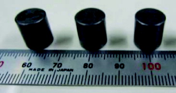
The fuel compacts are now under irradiation in WWR-K reactor at National Nuclear Center of the Republic of Kazakhstan (NNC). The irradiation test began in October 2012 and will finish in August 2014 [Citation19]. The target burnup and the target irradiation temperature are 100 GWd/t and 1323 ± 100 K, respectively [Citation18,19]. The fuel compacts are swept with He gas under irradiation, and the concentration of 88Kr in the sweep gas is monitored to detect the failure of CFP in the mode that IPyC, SiC and OPyC layers are all failed (the through-coating failure of the CFP) [Citation18], because 88Kr is not influenced by precursor nuclide. The history of the release rate to birth rate ratio (R/B) of 88Kr is calculated by the fission gas release model [Citation20,21] developed in the HTTR project with the irradiation temperature history and assumed number of the through-coating failed CFPs. The calculated history of R/B of 88Kr was compared with measured data to determine additional through-coating failure fraction of the CFP during irradiation.
shows the comparison between measured and calculated R/B of 88Kr as function of irradiation duration. The burnup of the fuel specimen attained around 26 GWd/t at the effective full power day (EFPD) of 104 day, and the measured R/B of 88Kr agreed well with the history calculated assuming no additional through-coating failure up to the EFPD of 100 day. Therefore, it was concluded that the integrity of the extended burnup fuel was confirmed at this level of burnup and in this irradiation temperature level.
Figure 4. Histories of irradiation temperature and release rate to birth rate ratio (R/B) of fission gas 88Kr. Estimated burnup is 26 GWd/t at effective full power of 100 day.
In addition to the above-mentioned irradiation test that is in progress, the irradiation tests at higher temperatures are planned. The maximum irradiation temperature of CFPs in the HTR50S would be rather higher than the irradiation temperature of 1323 ± 100 K. For example, the maximum irradiation temperature (estimated conservatively) of CFPs in the first core of the HTR50S was estimated to be 1740 K [Citation11].
2.1.2. R&D for fuel compact with high packing fraction
The CFPs are sintered into the fuel compacts to be put into the sleeves as follows. CFPs are over-coated with the graphite matrix and warm-pressed to make columnar or cylindrical green compacts. Green compacts are preliminarily heat treated for carbonization at 1073 K under nitrogen atmosphere, then sintered at 2073 K under vacuum to make fuel compacts [Citation22].
The volume fraction of the UO2 kernel to the whole of HTR50S2-type-CFP is only about 58% of that of the HTTR-type-CFP as calculated from . Then, the R&D for fuel compact with high packing fraction is planned so that enough uranium content in the core is preserved. Other countermeasures, for example increase of the volume of the fuel compact by increasing outer diameter of fuel compact and the inner diameter of the sleeve, may be needed in addition to the R&D to preserve enough uranium content.
2.1.3. Completion of proof of the nuclear/thermal design of the core on integrity of fuel
The R&D items, mentioned in Sections 2.1.1 and 2.1.2, are inseparably related to the nuclear/thermal design of the core. We plan to complete the proof of the nuclear/thermal design of the second core of the HTR50S on integrity of fuel, feeding back the results of the R&Ds and the nuclear/thermal design to each other.
2.2. R&D items that should be carried out
In this section, R&D items that should be carried out are described as follows:
First of all, research on safety is very important (Section 2.2.1). Safety is very important after the accident at the Fukushima Daiichi Nuclear Power Station.
R&Ds for improvement of fabrication technique of CFPs increase a degree of freedom for the nuclear/thermal design of the core (Section 2.2.2).
The strength of the SiC layer of Japanese CFPs is unknown, nevertheless it is essential for completion of the nuclear/thermal design of the core (Section 2.2.3).
Diffusion data of FPs, especially Cs, in the SiC layers increase a degree of freedom for the nuclear/thermal design of the core (Section 2.2.4).
These R&D items are useful or essential for other cores than the second core of the HTR50S in the future, as described later in Section 4.
2.2.1. Research on safety
One of the design extension conditions (DECs) for the HTGR is the large amounts of air/water ingress accident [Citation23]. It is desirable that the behavior, under severer conditions than those assumed accidents, can be understood for evaluation of safety of HTR50S, though, the large amount of air/water ingress will be prevented in the HTR50S by the containment vessel [Citation24]. The assumed outline of the research related to the CFPs and fuel compacts on the air/water ingress accidents is described below.
At first, oxidation data of dummy CFPs and dummy fuel compacts is planned to be obtained for the design of the reactor. The experimental identification of the condition to form the layer with stable oxide, i.e., silicon dioxide (SiO2), for SiC layer of the CFPs is the most important data [Citation23]. It should be noted that SiC layer is thinned and finally vanished in some oxidation conditions [Citation23]. In addition to the identification of the oxidation mode described in [Citation23], the mechanical strength of the oxidized CFPs are also important data and is planned to be obtained. The formation of the stable oxide layer on the SiC layer does not mean that the oxidized CFPs can confine the harmful materials whatever happens. The averaged fracture loads in the mono-axial fracture test of as-fabricated HTTR-CFPs are about 2–5 kgf [Citation25]. That is, about half of the HTTR-CFPs fail with the load of about 2–5 kgf, even if they are un-irradiated and their OPyC layers, the cushion of the SiC layers (see ), are not thinned with oxidation.
The results of this research item are essential for the design of the naturally safe HTGR (see Section 4), which JAEA proposed after the accident at the Fukushima Daiichi Nuclear Power Station [Citation23,Citation26,Citation27]. The specifications of the CFPs of the naturally safe HTGR are not determined yet, but the mode and the rates of the oxidation of the coating layers would be independent on the specifications.
2.2.2. R&D for improvement of fabrication technique of CFPs
Thickening of the SiC layer
The SiC layer is the main structural layer, as well as the barrier for metallic fission products, as shown in . Then, thick SiC layers can improve safety of the CFPs under any accident conditions. In addition, thicker SiC layers than HTR50S2-type-CFPs may be essential for the naturally safe HTGR, as mentioned later in Section 4.
Suppression of the dispersion in the thicknesses of the buffer layers
The buffer layer is the margin for kernel migration, as well as the plenum for the gases, as shown in . The sum of the thicknesses of buffer and IPyC layers is the sum of the limitation of the fuel kernel migration and the margin. And the margin depends on the dispersion in the thicknesses of the coating layers [Citation16]. The dispersion of the thicknesses of the buffer layers is especially large. Then the suppression of the dispersion in the thicknesses of the buffer layer can increase the limitation of the fuel kernel migration distance. The suppression of the dispersion would increase a degree of freedom for the nuclear/thermal design of the core. It should be noted that the maximum fuel kernel migration distance was estimated to be as much as 53.2 μm; on the other hand, the criterion was 55 μm, in the case of the first core of the HTR50S [Citation12].
2.2.3. Obtaining data of strength of SiC layer
A calculation code for the pressure vessel failure probability of CFPs under irradiation [Citation28,29] is one of the codes for the analytical estimation of the integrity of the fuel and essential for the completion of the nuclear/thermal design of the core. On the pressure vessel failure under the normal operation, the proof of the integrity of CFPs by irradiation tests are enough for the completion of proof of the nuclear/thermal design of the core on integrity of fuel. But the nuclear/thermal design of the core is completed based on the analytical estimation of the integrity of the fuel. Then, the wrong estimation may cause the great loss of time, through the re-design of the core.
In the pressure vessel failure probability calculation code, the strength of SiC layer is one of the most important material properties for the calculation. It is very difficult to obtain the mechanical data of the SiC layer, because it is a spherical shell with a thickness of some tens of micrometers and with a diameter less than 1 mm. We now use old German data for the strength of the SiC layer in our code [Citation29]. On the other hand, a good method to obtain the strength of the SiC layer was developed in the USA [Citation30] in the twenty-first century. In this method, the semi-spherical shells of SiC layers are picked out from the real CFPs or dummy CFPs, and the internal pressure is loaded in the inner surface of the SiC layers [Citation30].
If the strength data of the SiC layer is obtained by this method with the real SiC layer picked out from Japanese CFPs or dummy CFPs, the possibility that the integrity of the HTR50S2-type-CFPs can be properly estimated is increased.
2.2.4. Obtaining diffusion data of FPs (especially Cs) in SiC layer
It is important to limit the amount of the released FPs, especially Cs, from the fuel during the normal operation as well as the accident to limit the public exposure. The FPs, which are released from the fuel under the normal operation and retained in the core and on the pipes, are released to the environment under some accident conditions. The diffusion coefficient of Cs in the SiC layer is a very important parameter for the estimation of the release amount of Cs from the fuel, because the SiC layer is the barrier for the metallic FPs as shown in .
On the other hand, the release amount of Cs from the very latest manufacture of German TRISO CFPs during the post-irradiation heating test was largely overpredicted by calculation [Citation31]. The large overprediction can be caused by improvement of the fabrication technology of the CFPs. The calculation was carried out with old diffusion coefficients. It should be noted that the SiC layer is not a single crystal without defect.
Therefore, a degree of freedom for the nuclear/thermal design of the core would be increased, if the diffusion data of Cs is obtained with the CFPs fabricated in Japan in the twenty-first century.
3. Core of HTGR50S in phase II
The core of the HTR50S will be upgraded to the core in phase II after phase I [Citation11]. The outlet coolant temperature will be increased to 1173 K [Citation11] in phase II.
The maximum fuel temperature was estimated to be 1740 K [Citation11], which is only 28 K lower than the criteria of the maximum fuel temperature (1768 K [Citation11]), in the first core of the HTR50S, nevertheless the outlet temperature is 150 K lower than that of the core of the HTR50S in phase II [Citation11]. Therefore, the following subjects (1) and/or (2) are needed to complete the draft of the nuclear/thermal design of the core, at least.
Nuclear/thermal design to reduce the fuel temperature.
Fuel with high heat conductivity.
For example, a type of sleeveless fuel rod (monolithic fuel) was used for the design of the GTHTR300 [Citation10], and the estimated high performance of the GTHTR300 was based on the predicted high heat conductivity of the sleeveless fuel rod. A sleeveless fuel rod is a fuel rod without sleeve, that is, a columnar or cylindrical fuel compact (fuel region) which is partially or fully covered with the non-fuel region. The non-fuel region consists of the same material as the graphite matrix of the fuel compact. In the case of the sleeveless fuel rod used in the design of the GTHTR300, only the outer periphery of a cylindrical fuel compact was covered with the non-fuel region with a thickness of 1 mm [Citation32]. The radial thermal conductivity of a sleeveless fuel rod would be higher than that of a fuel rod with sleeve, because the gap between the fuel compact and the sleeve is a great barrier for heat conductivity.
4. Future outlook
JAEA is planning to begin the design of the practical HTGR in Japan in future, a naturally safe HTGR, continuing the design of the HTR50S and the GTHTR300. The design concept of the naturally safe HTGR is a modified GTHTR300 to improve the safety. The policy of the fuel of the naturally safe HTGR is decided to be the SiC–TRISO CFPs with UO2 kernels sintered with graphite matrix, as the HTTR. The situation, that all naturally safe HTGRs designed in Japan cannot be realized without technologies which are challenging and/or are very costly to develop, i.e., no one knows whether naturally safe HTGR in Japan can be realized or not, has to be avoided. We will design the naturally safe HTGR which is as economical as possible, feeding back the specifications of the fuel, design of the system (including the nuclear/thermal design of the core) and the cost evaluation.
For the design of the system, the following two research items (1) and (2) are essential.
Research on safety (see Section 2.2.1).
Obtaining diffusion data of FPs (especially Cs) in SiC layer (see Section 2.2.4).
The “new” diffusion coefficients of FPs in the SiC layers would also be essential. It is forecasted to be impossible to design the naturally safe HTGR with both of the economy and the safety in view of public dose in accident, if the amount of the released FPs is estimated with too conservative diffusion coefficients. Then this R&D item will be planned in future.
The average burnup of the CFPs of the naturally safe HTGR should be higher than that of the HTR50S for economy and reduction of waste, though, the specifications of the CFPs cannot be determined without the feeding back of the specifications of the fuel, design of the system and the cost evaluation. The following R&D items (3)–(6) are needed for the CFPs for higher burnups than those for the HTR50S at least. The necessity of the items (4)–(6) is caused by the small volume fraction of the UO2 kernel in the CFP for high burnup as described in Section 2.1.2.
| (3) | Thickening of the SiC layer (see Section 2.2.2). | ||||
| (4) | Suppression of the dispersion in the thicknesses of the buffer layers (see Section 2.2.2). | ||||
| (5) | R&D for fuel compact with high packing fraction (see Section 2.1.2). | ||||
| (6) | R&D for suppression of the failure of the CFPs with thin OPyC layer by handling. | ||||
Thin OPyC layers in specifications can decrease the total volume of CFPs, and can increase the volume fraction of fuel kernel in CFPs. On the other hand, thin OPyC layers would cause increase in the failure of the CFPs by handling, because OPyC layers are the cushion for SiC layer as shown in . Then, the R&D for the suppression of the failure of the CFPs by handling would be needed for the fabrication of the CFPs for the naturally safe HTGR.
5. Summary
The plan and the status of the R&Ds for the CFPs and fuel compact for the HTR50S and the naturally safe HTGR are described as follows:
| (1) | We described the plan and the status of the R&Ds on the CFPs and the fuel compacts for the second core of the HTR50S, for which the basic specifications of the fuel have been drafted.
| ||||||||||||||||||||||||||||||||||||||||
| (2) | The core of the HTR50S will be upgraded into the core in phase II, after phase I. The outlet coolant temperature will be increased to 1173 K in phase II, which is 150 K higher than that for phase I. Therefore, the nuclear/thermal design to reduce the fuel temperature and/or fuel with high heat conductivity is needed to complete the nuclear/thermal design of the core. | ||||||||||||||||||||||||||||||||||||||||
| (3) | A plan to begin the design of a naturally safe HTGR, the practical HTGR in Japan in future, is shown. The policy of the fuel of the naturally safe HTGR is decided to be the same type as the HTTR. The R&D items on fuel for the naturally safe HTGR are also shown. | ||||||||||||||||||||||||||||||||||||||||
Acknowledgements
The authors wish to express their gratitude for constructive comments and the guidance from Dr H. Ohashi of Japan Atomic Energy Agency (JAEA). The present study includes the result of “Development for Advanced High Temperature Gas Cooled Reactor Fuel and Graphite Components” entrusted to the JAEA by the Ministry of Education, Culture, Sports, Science and Technology of Japan (MEXT).
This article was originally published with errors. This version has been corrected. Please see Corrigendum http://dx.doi.org/10.1080/00223131.2014.934526
References
- Fukuda K, Ogawa T, Hayashi K, Shiozawa S, Tsuruta H, Tanaka I, Suzuki N, Yoshimuta S, Kaneko M. Research and development of HTTR coated particle fuel. J Nucl Sci Technol. 1991;28:570–581.
- Sawa K, Yoshimuta S. Design of coated fuel particle for high burnup high temperature gas-cooled reactor. Tokai-mura (Japan): Japan Atomic Energy Research Institute; 1998. Japanese.
- Goto M, Seki Y, Inaba Y, Ohashi H, Sato H, Fukaya Y, Tachibana Y. Conceptual design of small-sized HTGR system (II) – nuclear design. Tokai-mura (Japan): Japan Atomic Energy Agency; 2012. Japanese.
- Ueta S, Aihara J, Sakaba N, Honda M, Furihata N, Sawa K. Fuel performance under continuous high temperature operation of the HTTR. J Nucl Sci Tech. 2014.
- Saito S, Tanaka T, Sudo Y, Baba O, Shindo M, Shiozawa S, Kobayashi F, Kurihara R, Hada K, Yamashita K, Kawasaki K, Iyoku T, Kunitomi K, Maruyama S. Design of high temperature engineering test reactor (HTTR). Tokai-mura (Japan): Japan Atomic Energy Agency; 1994.
- Fujikawa S, Okubo M, Nakazawa, T, Kawasaki K, Iyoku T. [Rise-to-power test of the HTTR (high temperature engineering test reactor)]. Nihon-Genshiryoku-Gakkai-Wabun-Ronbun-Shi (J At Energy Soc Jpn). 2002;1:361–372. Japanese.
- Fujikawa S, Hayashi H, Nakazawa T, Kawasaki K, Iyoku T, Nakagawa S, Sakaba N. Achievement of reactor-outlet coolant temperature of 950C in HTTR. J Nucl Sci Technol. 2004;41:1245–1254.
- Ueta S, Aihara J, Sawa K, Yasuda A, Honda M, Furihata N. Development of high temperature gas-cooled reactor (HTGR) fuel in Japan. Prog Nucl Energy. 2011;53:788–793.
- Ohashi H, Sato H, Tazawa Y, Yan XL, Tachibana Y. Conceptual design of small-sized HTGR system (I) – major specifications and system designs. Tokai-mura (Japan): Japan Atomic Energy Agency; 2011. Japanese.
- Katanishi S, Kunitomi K, Takei M, Nakata T, Watanabe T, Izumiya T. [Feasibility study on high burnup fuel for gas turbine high temperature reactor (GTHTR300), (I)]. Nihon-Genshiryoku-Gakkai-Wabun-Ronbun-Shi (J At Energy Soc Jpn). 2002;1:373–383. Japanese.
- Ohashi H, Sato H, Goto M, Yan X, Sumita J, Tazawa Y, Nomoto Y, Aihara J, Inaba Y, Fukaya Y, Noguchi H, Imai Y, Tachibana Y. A small-sized HTGR system design for multiple heat applications for developing countries. Int J Nucl Ener. 2013; 2013: Article ID 918567.
- Aihara J, Goto M, Inaba Y, Isaka K, Ohashi H, Tachibana Y. Preliminary evaluation of integrity of coated fuel particles under normal operation in core of small-sized HTGR system HTR50S at 1st. step of phase I. Tokai-mura (Japan): Japan Atomic Energy Agency; 2014. (no. JAEA-Technology 2014-009).
- Ueta S, Aihara J, Honda M, Furihata N, Sawa K. Development of high temperature gas-cooled reactor fuel for extended burnup. Proceedings of the 18th International Conference on Nuclear Engineering; 2010 May 17–21; Xi'an (China) (ICONE18-29206).
- Aihara J, Ueta S, Shibata T, Sawa K. [Suggested failure probability calculation method for Japanese high-quality high-temperature gas-cooled reactor (HTGR) fuel]. Nihon-Genshiryoku-Gakkai-Wabun-Ronbun-Shi (J At Energy Soc Jpn). 2012;11:158–163. Japanese.
- Sawa K, Tobita T, Takahashi M, Saito T, Iimura K, Yokouchi I, Serizawa H, Sekino H, Ishikawa A. [Irradiation test of high burnup coated fuel particles for high temperature gas-cooled reactor (91F-1A sweep gas capsule irradiation test)]. Tokai-mura (Japan): Japan Atomic Energy Agency; 2001. Japanese.
- Hayashi K, Sawa K, Shiozawa S, Fukuda K. Assessment of fuel integrity of the high temperature engineering test reactor (HTTR) and its permissible design limit. Tokai-mura (Japan): Japan Atomic Energy Agency. 1989. Japanese.
- Sawa K, Tobita T, Mogi H, Shiozawa S, Yoshimuta S, Suzuki S, and Deushi K. Fabrication of the first-loading fuel of the high temperature engineering test reactor. J Nucl Sci Technol. 1999;36:683–690.
- Ueta S, Aihara J, Mizutani Y, Ohashi H, Sakaba N, Tachibana Y, Honda M, Tanaka H, Furihata N. Conceptual design study of small-sized high temperature gas-cooled reactor for developing countries (3) fuel design. Proceedings of the Annual Meeting of Atomic Society of Japan; 2013 March 26–28; Higashiosaka (Japan) (G09). Japanese.
- Ueta S, Mizutani Y, Sakaba N, Honda M, Furihata N, Shaimerdenov A, Gizatulin S, Chakrov P. Collaboration with Republic of Kazakhstan regarding development of HTGR (2) collaboration of irradiation performance of HTGR fuel. Proceedings of the Fall Meeting of Atomic Society of Japan; 2013 Sep 3–5; Hachinohe (Japan). G40. Japanese.
- Sawa K, Minato K, Fukuda K. Development of an evaluation method of fission product release fraction from high temperature gas-cooled reactor fuel. Tokai-mura (Japan): Japan Atomic Energy Research Institute; 1996. Japanese.
- Ueta S, Sumita J, Emori K, Takahashi M, Sawa K. Fuel and fission gas behavior during rise-to-power test of the high temperature engineering test reactor (HTTR). J Nucl Sci Technol. 2003;40:679–686.
- Kato S, Yoshimuta S, Hasumi T, Sato K, Sawa K, Suzuki S, Mogi H, Shiozawa S, Tanaka T. Fabrication of HTTR first loading fuel. Vienna (Austria): IAEA-TECDOC-1210. 2001 Apr; 187–199.
- Ueta S, Sumita J, Shibata T, Aihara J, Fujita I, Ohashi J, Nagaishi Y, Muto T, Sawa K, Sakaba N. R&D plan for development of oxidation-resistant graphite and investigation of oxidation behavior of SiC coated fuel particle to enhance safety of HTGR. Nucl Eng Des. 2014;271:309–313.
- Ohashi H, Sato H, Tazawa Y, Aihara J, Nomoto Y, Imai Y, Goto M, Isaka K, Tachibana Y, and Kunitomi K. Conceptual design of small-sized HTGR system (V) – safety design and preliminary safety analysis. Tokai-mura (Japan): Japan Atomic Energy Agency; 2014. Japanese.
- Ueta S, Izumiya T, Umeda M, Ishigaki Y, Ohashi J, Iyoku T. Database of fabrication characteristics of the second-loading-fuel for the high temperature engineering test reactor (I) – fuel kernels, coated fuel particles and fuel compacts. Tokai-mura (Japan): Japan Atomic Energy Research Institute; 2006. Japanese.
- Ohashi H, Sato H, Tachibana Y, Kunitomi K, Ogawa M. Feasibility study on naturally safe HTGR for air ingress accident. Nucl Eng Des. 2014; 271: 537–544.
- Ohashi H, Sato H, Kunitomi K, Ogawa M. [Concept on inherent safety in high-temperature gas-cooled reactor]. Nihon-Genshiryoku-Gakkai-Wabun-Ronbun-Shi. (J At Energy Soc Jpn). 2014;13:17–26. Japanese.
- Aihara J, Ohashi H, Sawa K, Tachibana Y. Code-B-2 for stress calculation for SiC-TRISO fuel particle. Tokai-mura (Japan): Japan Atomic Energy Agency; 2013. Japanese.
- Sawa K, Sumita J, Watanabe T. Fuel failure and fission gas release analysis code in HTGR. Tokai-mura (Japan): Japan Atomic Energy Agency; 1999. Japanese.
- Hong SG, Byun TS, Lowden RA, Snead LL, Katoh Y. Evaluation of the fracture strength for silicon carbide layers in the tri-isotropic-coated fuel particle. J. Am. Ceram. Soc. 2007; 90: 184–191.
- IAEA TECDOC. Advances in high temperature gas cooled reactor fuel technology. Vienna (Austria): International Atomic energy Agency; 2012.
- Nakata T, Katanishi S, Takada S, Yan X, Kunitomi K. Nuclear design of the gas turbine high temperature reactor (GTHTR300) (contract research). Tokai-mura (Japan): Japan Atomic Energy Agency; 2002. Japanese.