
 ?Mathematical formulae have been encoded as MathML and are displayed in this HTML version using MathJax in order to improve their display. Uncheck the box to turn MathJax off. This feature requires Javascript. Click on a formula to zoom.
Abstract
The fluid–structure interaction (FSI) effect should be carefully considered in a seismic analysis of nuclear reactor internals to obtain the appropriate seismic responses because the dynamic characteristics of reactor internals change when they are submerged in the reactor coolant. This study suggests that a seismic analysis methodology considered the FSI effect in an integral reactor, and applies the methodology to the System-Integrated Modular Advanced Reactor (SMART) developed in Korea. In this methodology, we especially focus on constructing a numerical analysis model that can represent the dynamic behaviors considered in the FSI effect. The effect is included in the simplified seismic analysis model by adopting the fluid elements at the gap between the structures. The overall procedures of the seismic analysis model construction are verified by using dynamic characteristics extracted from a scaled-down model, and then the time history analysis is carried out using the constructed seismic analysis model, applying the El Centro earthquake input in order to obtain the major seismic responses. The results show that the seismic analysis model can clearly provide the seismic responses of the reactor internals. Moreover, the results emphasize the importance of the consideration of the FSI effect in the seismic analysis of the integral reactor.
1. Introduction
In Korea, a small modular reactor, the System-Integrated Modular Advanced Reactor (SMART), was developed as a next-generation reactor. Unlike conventional reactors, SMART is an integrated structure that includes the main components of the reactor coolant system (RCS) in a single reactor vessel (RV). This system improves safety by eliminating large primary system pipes and prevents large break loss of coolant accident (LBLOCA).
Structural integrity of the reactor needs to be verified to confirm safety during construction. In structural integrity assessment, the dynamic behavior of the reactor internals should be determined when they are exposed to both internal and external vibration sources. Earthquakes are the main source of external vibrations that can cause critical damage to reactor internals. Thus, the seismic analysis is carried out for obtaining the seismic responses of reactor internals following the conventional criteria [Citation1]. The new developing reactors follow the criteria and suggest original seismic analysis methodologies adapting their properties [Citation2–5].
The internals of the small modular integral reactor such as the SMART use a new design concept that requires new methodologies for seismic analysis because their dynamic behaviors are different from those of conventional reactor internals. In the reactor internals, components are submerged in the reactor coolant, which causes the fluid–structure interaction (FSI) effect that changes the dynamic characteristics of the structures such as natural frequencies and mode shapes. In the integral reactor, components are arranged closely together and surrounded by a gap fluid between the structures. The narrow fluid gap increases the added mass effect and produces the coupled dynamic behaviors between adjacent structures, such as the out-of-phase and in-phase modes [Citation6]. Thus, seismic analysis needs to consider the influence of the FSI effect on the dynamic characteristics of reactor internals in order to obtain reliable seismic responses.
In this study, a seismic analysis method appropriate to the integral reactors is suggested and applied to SMART internals. The analysis focuses on developing a simplified seismic analysis model that can account for dynamic behavior under the complex FSI effect. To achieve this, the modeling procedures of the seismic analysis model are subdivided for applying accurate geometry, material properties, and boundary conditions that can affect the dynamic characteristics. For the FSI, the added mass effect from the fluid gap and dynamic coupling of the co-axial structures are carefully considered. All procedures were verified with dynamic characteristics obtained from the finite element (FE) method with a detailed three-dimensional (3D) FE model and experiments using a manufactured scaled-down model of the SMART internals [Citation7,8]. Using the developed seismic analysis model, we carried out a time history analysis for the real size SMART internals using the El Centro earthquake records. The results of the seismic analysis are identified and discussed with emphasis on the FSI effect.
2. Description of the SMART internals
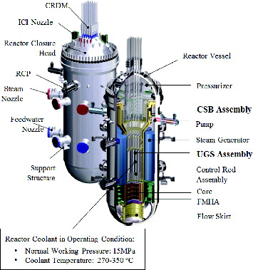
shows the reactor vessel and internal structures of the SMART system [Citation9]. As shown in , the system includes main components such as the reactor coolant pumps, pressurizer, steam generators, and fuel assemblies in one RV. This structure enhances safety by preventing LBLOCA. However, these concentrated structures can create problems when they interact with the reactor coolant, which generates the FSI effect that decreases the overall natural frequencies of the components and the coupling behaviors between the structures. In particular, the co-axial cylindrical structures with a high slenderness ratio, the core support barrel (CSB) assembly and upper guide structure (UGS) assembly, have low-frequency bending modes to seismic hazard when they are submerged. Thus, this research focuses on the seismic behaviors of these two structures.
Figure 1. Schematic configuration of the SMART.
3. Seismic analysis
Seismic analysis is performed to identify the seismic responses of reactor internals during an earthquake. Time history analysis is the most commonly used method and uses acceleration time histories of artificial earthquakes for seismic input in order to obtain time-dependent seismic responses of the structures. In this research, the commercial FE analysis program ANSYS (version 13.0) is used for performing the seismic analysis.
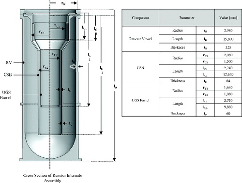
In FE analysis, the accuracy of the results depends on the number of nodes and elements. Therefore, 3D FE models, which can represent the detailed dynamic characteristics of the structures, are generally used in static analyses such as modal analysis. However, such models are unsuitable for dynamic analysis, which needs to calculate the numerous equations of motion and constraints from the FSI effect in each of many time steps. Thus, previous researchers provide several methods to reduce analysis time and cost by simplifying the FE model or analysis process. The 1D FE model, which consists of the beam, lumped mass, and spring elements, is a simplified numerical model commonly used in seismic analysis [Citation10–12]. It is a suitable model because it can precisely and more simply include principal modes, such as bending modes that are most affected by seismic input. In this research, we constructed a simplified seismic model of the SMART reactor internals and demonstrated its validity by comparing the model with results from a modal analysis of a scaled-down model [Citation8]. provides the primary dimensions of the major structures used in the seismic analysis. In addition, shows material properties of the structures and the inner coolant employed in the analysis.
Table 1. Material properties applied to the FE analysis model.
Figure 2. Geometric information of the SMART internals using in the analysis.
In general, the seismic analysis is classified into response spectrum analysis and time history analysis. The time history analysis is more accurate because it uses the numerical integration technique under the time domain in order to calculate seismic responses over thousands of time steps. In this study, several seismic responses are identified and assessed as follows:
response time histories (displacement, velocity, and acceleration);
response spectrum at specific locations;
moment and shear force time histories.
3.1. FSI problem in the SMART internals
When the reactor internals are submerged in the reactor coolant, they are affected by the FSI effect generated from the fluid reaction force. The FSI effect results in the added mass effect and dynamic coupling of the adjacent structures. When the co-axial cylindrical structures are submerged, the governing equation can be expressed as
(1)
(1)
Using the Fritz formula, the reacting forces of fluid is expressed as the equation of the fluid gap and geometries of the cylinders [Citation13]:
(2)
(2) where
(4)
(4) and
(5)
(5)
Substituting Equation (2) into Equation (1), the equation of motion is rearranged as
(6)
(6)
From the mass term in Equation (6), the adjacent co-axial cylindrical structures show coupled behaviors when they are submerged.
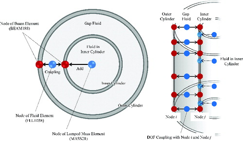
In this study, we design the seismic analysis model as shown in in order to consider the FSI effect in the SMART internals. The coolant located inside the UGS barrel is modeled by the lumped mass element, considering the hydrodynamic mass (MH). In addition, the coolant located between the structures is modeled by the fluid element which is based on the Fritz theory [Citation13]. Degrees of freedom of the fluid element and adjacent beam elements are coupled together in order to apply the dynamic coupling effects from the fluid gap.
Figure 3. FSI effect consideration in the seismic analysis model.
3.2. Seismic analysis model design
A simplified seismic analysis model can rapidly and efficiently provide seismic responses of reactor internals. However, it needs to verify the validity of the analysis model considering the uncertainty from the simplification. Thus, the constructed seismic analysis model is validated by comparing the results to a modal analysis of the detailed 3D FE model using the following steps.
First, the components of the reactor internals are modeled separately with the elastic beam element which is based on the Timoshenko beam theory. represents the designed beam element models of the main structures in the SMART. As depicted in , the sectional information of the reactor components applies precisely to the beam elements so as to preserve the original material properties (Young's modulus and density) that can affect the dynamic characteristics. To improve accuracy, the seismic analysis model is divided sufficiently in the axial direction according to the cross section shapes and sufficient nodes are placed to each division in order to observe the accurate bending modes of the structures. FE models of the inner structures of the CSB and UGS assemblies (the fuel assembly, core shroud, and UGS guide plates) are also constructed to consider the inertial mass and the bending stiffness.
Figure 4. Design of beam element models of major components in the SMART.
Second, seismic analysis models of partially assembled reactor components are constructed in order to determine the boundary conditions. In the SMART system, the CSB and UGS assemblies are clamped along the upper flange of the RV. This boundary condition exercises dominant influence in the first bending mode (i.e., translational vibration mode) of the reactor internals. The boundary condition in the simplified seismic model uses the spring element to consider the deflection of the flange and the hold-down ring, with the torsional spring constant calculated from the results of the 3D FE model. lists the natural frequencies and mode shapes of the partially assembled reactor internals extracted from the simplified seismic analysis model and detailed 3D FE model. It compares two modes of the CSB and UGS assemblies for m = 1 bending mode and m = 2 bending mode (m is the number of nodal lines in the axial direction). The results show that the dynamic characteristics from the simplified seismic beam model are well matched with those of the 3D FE model within 7% error. That means that the simplified beam model is well designed by applying the boundary conditions and dynamic characteristics of the original reactor internals.
Table 2. Dynamic characteristics of the partially assembled reactor internals from the two models without fluid.
Third, the FSI effect is applied to the analysis model constructed in the previous step. It is important to estimate the decrease in the overall natural frequencies of the internal structures generated by the added mass effect owing to the FSI. The lumped mass element is used to account for the added mass effect from the contained fluid inside of the CSB or UGS assembly. In addition, the fluid between the RV and other cylindrical structures is modeled with the fluid element. shows the dynamic characteristics of the partially assembled reactor internals in contact with the coolant from the two models. The error between the two models indicates that the FSI effect is well applied to the simplified model. In addition, the first bending mode natural frequencies of the CSB and UGS assemblies drop approximately 20% and 37%, respectively, according to the added mass effect. It shows that the decrease in the first bending mode natural frequency of the CSB assembly is less than the UGS assembly because the total mass of the CSB assembly, which contains the fuel assembly, is heavier than that of the UGS assembly.
Table 3. Dynamic characteristics of the partially assembled reactor internals from the two models including fluid.
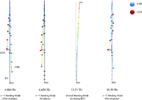
Fourth, the completed seismic analysis model of the reactor internals assembly includes the partially constructed models and boundary conditions determined in the prior steps. demonstrates the established simplified seismic analysis models of the SMART internals. The number of elements used in the seismic analysis model of the reactor internals assembly is listed in . The CSB and UGS assemblies are attached to the reactor vessel with the identified spring constants from the partially assembled models. In submerged co-axial cylinders such as the CSB and UGS assemblies, the coolant in the structural gaps generates dynamic coupling between the structures [Citation13]. In the seismic analysis model, this effect is carefully reflected to confirm the seismic responses under the FSI effect. To achieve this, fluid elements are adopted for the fluid gap between each cylinder (RV, CSB assembly, and UGS assembly) and that can account for the coupling effect from the FSI. lists the results of the modal analysis with the completed seismic analysis model. In addition, lists the comparison of the dynamic characteristics of the principal modes in two different models (3D FE model and simplified seismic analysis model), and illustrates mode shapes from the seismic analysis model. shows that the differences in the natural frequencies of the principal modes between the 3D FE model and the simplified seismic model are less than 5%. The mode shapes from the seismic analysis model illustrate that the dynamic coupling from the FSI is well applied. In addition, the first bending mode natural frequencies of the CSB and UGS assemblies drop approximately 43% and 44%, respectively. It indicates that the added mass effect is increased according to the fluid located in the narrow gap between the CSB and UGS assemblies.
Table 4. The number of elements used in the seismic analysis model of the reactor internals assembly.
Table 5. Results of the modal analysis with the totally assembled reactor internals.
Table 6. Principal modes of the totally assembled reactor internals from the two models including fluid.
Figure 5. The simplified seismic analysis beam models of the reactor internals.
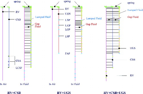
Figure 6. Major mode shapes of the seismic analysis model.
3.3. Time history analysis
3.3.1. Base excitation
In the time history analysis, acceleration time histories of the earthquake are used as the base excitation input of the whole structure that includes the reactor building and internals. In this study, the seismic input is directly transmitted to the bottom of the RV as the base excitation without considering the reactor building. The acceleration time histories of the 1940 El Centro earthquake (north–south direction) was used as the seismic input () [Citation14]. These acceleration time histories satisfy the safe shutdown earthquake (SSE) with 0.3g maximum peak ground acceleration based on the design criteria of the SMART [Citation15].
Figure 7. North-south El Centro earthquake input.
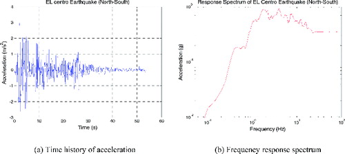
The large-mass method is adopted as the base excitation method, which assumes the ground as the large mass. In this case, the whole structure is connected to the large mass, to which the input acceleration is transmitted. The method shows reasonable results when the large mass is sufficiently large compared with the total mass of the structure [Citation16].
3.3.2. Response histories
The response histories at the major locations of the structures are important to understanding the seismic responses to an earthquake. These responses include displacement, velocity, and acceleration of the structures with respect to the input acceleration time histories of the earthquake. In this research, the acceleration time histories of the El Centro earthquake were applied to the base of the RV in the horizontal direction.
The response histories were measured at the top, bottom, and middle of the CSB and UGS assemblies ( and ). In the SMART, several snubbers and alignment keys are installed between the structures with small gaps in order to limit the lateral vibration at the bottom of the CSB and UGS assemblies. In this study, however, the bottom of the CSB and UGS assemblies are assumed as the free boundary condition to observe an artificially exaggerated lateral vibration under the seismic event. The CSB assembly shows a large dynamic displacement at 10–15 s, and the peak displacement (12.531 mm) occurs at the bottom of the CSB assembly at 11.70 s. The UGS assembly shows responses similar to those of the CSB assembly; a large oscillation appears at 10–15 s, and the peak displacement (13.434 mm) occurs at the bottom of the UGS assembly at 12.88 s. After the peak displacement, the oscillations of the CSB and UGS assemblies stabilize gradually, and the assemblies show out-of-phase oscillations after 31 s. Compared with the bottom, the deformation of the structures at the middle and top is small, less than 4 mm. Judging from the displacement histories at each location, the two structures move with n = 1 bending mode under the same phase in this period. Although the in-phase n = 1 bending mode is dominant under seismic load, and it causes the largest responses at the bottoms of the reactor components, in the real system, the large deformations might be drastically reduced due to the constraints, such as snubbers and alignment keys.
Figure 8. Response time histories of the CSB assembly.
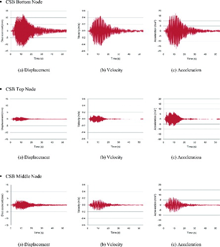
Figure 9. Response time histories of the UGS assembly.
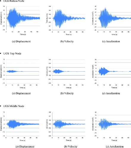
Acceleration responses show behaviors similar to the displacement responses. The acceleration amplitudes at the bottoms of the CSB and UGS assemblies are larger than that at the other measured points at 10–15 s when the structures experience intense vibration, indicating that the bottom of the structure is greatly affected by the seismic load. The peak acceleration at the bottom of the CSB assembly is 17.41 m/s2 at 11.30 s, and that at the bottom of the UGS assembly is 18.76 m/s2 at 11.96 s. Therefore, the acceleration is amplified about five times compared with the original maximum input (3.4104 m/s2).
3.3.3. Response spectrum
The response spectrum is the plot of the maximum response under the frequency domain when the structure is assumed to be a series of single degree of freedom oscillators. The response spectrum at a specific location can be calculated from the response histories in the time history analysis. The generated response spectra can be applied to the response spectrum analysis, which is an essential and economical method to calculate the base shear, the overturning moment, and the stress of particular structures in the reactor such as the reactor coolant pumps and fuel assemblies.
The response spectrum can be used to evaluate the maximum responses of the structures at specific points. shows the produced response spectrum from the response histories developed from the time history analysis with the 4% damping ratio used for welded steel structures [Citation17]. The selected points are the locations with the largest responses:
Figure 10. Response spectra generated using time history analysis.
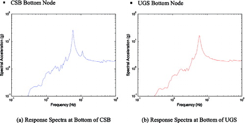
the bottom of the CSB assembly;
the bottom of the UGS assembly.
As shown in the response spectrum, several peaks appear near the natural frequencies of the structure. In the response spectrum at the bottom of the CSB assembly, the maximum peak appears near the in-phase bending mode frequency. On the contrary, the response near the out-of-phase bending mode frequency shows a smaller value. The maximum response of the UGS assembly also appears near the in-phase bending mode frequency, in accordance with the coupling behaviors expected from the FSI.
3.3.4. Moment and shear histories
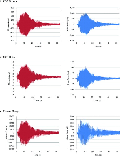
The seismic load calculated from the time history analysis is an important design criterion to assess the structural integrity of reactor internals. It can be applied to the stress analysis in combination with other design loads. In this research, the bending moment and shear force generated by the seismic responses of the reactor components are identified at several locations:
the bottom of the CSB assembly;
the bottom of the UGS assembly;
the flange of the RV.
represents the moment and shear force time histories at the chosen locations. It shows that the maximum seismic load is generated at the flange of the reactor vessel where the CSB and UGS assemblies are assembled. It is because the maximum responses occur at the bottom of the CSB and UGS assemblies according to the oscillations of the structures. Thus, the moment histories have similar tendencies compared to the response histories at the bottom of the reactor internals. The moment acting on the flange of the RV increased dramatically after 5 s, and the maximum moment (20,170 kN m) occurred at 11.7 s, when the response of the CSB assembly was maximized. These results also demonstrate that the in-phase oscillations of the reactor components amplify the seismic load at a fixed location. Shear force oscillates with the moment, increasing after 5 s and continuing at high amplitude until 15 s. The maximum shear force is 2217 kN in the positive direction at 9.1 s and 2220 kN in the negative direction at 5.7 s. Compared with the seismic load at the flange of the RV, the moment and shear force at the bottom of the UGS assembly are negligible. The CSB assembly shows larger values than the UGS assembly as a result of the oscillations of the fuel assembly and core shroud, which are fixed to the bottom of the CSB assembly.
Figure 11. Moment and shear force time histories.
4. Conclusion
This research suggests a methodology for the seismic analysis of an integral reactor, which can be greatly affected by the FSI effect. This methodology focuses on the construction of a simplified seismic analysis model that reflects the dynamic characteristics of a modal analysis from a scaled-down model of the reactor internals. That simplified model was applied to the SMART in order to identify seismic responses and generate seismic load. The results are summarized as follows.
The seismic analysis model was developed by reducing the overall number of nodes and elements using beam, lumped mass, and spring elements. It also considers the FSI effect, including the added mass effect and dynamic coupling of the structures using the fluid element.
The seismic analysis model was verified with the results from the modal analysis with the detailed 3D FE model. The results show that the simplified seismic analysis model well represents the original dynamic characteristics of the reactor internals (i.e., natural frequencies and mode shapes are well matched).
A time history analysis was performed with the simplified seismic model using the acceleration time histories of the El Centro earthquake. The displacement response histories at the bottoms of the CSB and UGS assemblies had the largest values. The peak values of the displacements were 12.531 mm (CSB assembly) and 13.434 mm (UGS assembly). The results demonstrated that the space between the structures is sufficiently wide to prevent a collision due to the deformation. The acceleration response histories showed a tendency similar to the displacement response histories. The peak values at the bottom of the CSB and UGS assemblies were 18.644 and 18.270 m/s2, respectively.
The response spectra are calculated from the response histories at the bottom of the reactor internals. They demonstrate the maximum responses of the CSB and UGS assemblies under the frequency domain and show that the maximum peak value occurs near the in-phase bending mode frequency.
The seismic load, including the moment and shear force, was calculated at several locations. The maximum moment and shear force occurred at the flange of the RV due to the oscillation of the reactor internals. The time histories of the moment and shear force have trends similar to the response histories of the bottoms of the reactor internals.
The overall results show that the simplified seismic analysis model provides correct seismic responses of the reactor internals. Based on the results, the FSI effect has a dominant influence on seismic responses. For this reason, seismic analysis using the dynamic characteristics from the scaled-down model is an effective way to obtain reliable responses of submerged reactor internals.
References
- Newmark NM, Hall WJ. Seismic design criteria for nuclear reactor facilities. Proceedings of the Fourth World Conference on Earthquake Engineering; 1969 Jan 13–18; Santiago (Chile).
- Sigrist JF, Broc D, Laine C. Dynamic analysis of a nuclear reactor with fluid structure interaction. Part 1: seismic loading, fluid added mass and added stiffness effects. Nucl Eng Des. 2006;236:2431–2443.
- Lo Franco R, Forasassi G. Conceptual evaluation of fluid–structure interaction effects coupled to a seismic event in an innovative liquid metal nuclear reactor. Nucl Eng Des. 2009;239:2333–2342.
- Lo Franco R, Forasassi G. Preliminary evaluation of the seismic response of the ELSY LFR. Nucl Eng Des. 2012;242:361–368.
- Zhao C, Chen J. Numerical simulation and investigation of the base isolated NPPC building under three-directional seismic loading. Nucl Eng Des. 2013;265:484–496.
- Chen SS, Rosenberg GS. Dynamics of a coupled shell-fluid system. Nucl Eng Des. 1975;32:302–310.
- Lim SH, Choi YI, Ha K, Park KS, Park NC, Park YP, Jeong KH, Park JS. Dynamic characteristics of a perforated cylindrical shell for flow distribution in SMART. Nucl Eng Des. 2011;241:4079–4088.
- Choi YI, Lim SH, Ko BH, Park KS, Park NC, Park YP, Jeong KH, Park JS. Dynamic characteristics identification of reactor internals in SMART considering fluid–structure interaction. Nucl Eng Des. 2013;255:202–211.
- Lee WJ. The SMART reactor. Proceedings of the 4th Annual Asian-Pacific Nuclear Energy Forum; 2010 Jun 18–19; Berkeley (CA).
- Jhung MJ, Hwang WG. Seismic response of reactor vessel internals for Korean standard nuclear power plant. Nucl Eng Des. 1996;165:57–66.
- American Society of Civil Engineers. Seismic analysis of safety-related nuclear structures and commentary. Reston (VA): American Society of Civil Engineers; 1999.
- Yoo B, Lee JH, Koo GH, Lee HY, Kim JB. Seismic base isolation technologies for Korea advanced liquid metal reactor. Nucl Eng Des. 2000;199:125–142.
- Fritz RJ. The effect of liquids on the dynamic motions of immersed solids. J Eng Ind Trans ASME. 1972;94:167–173.
- Chopra AK. Dynamics of structures: theory and application to earthquake engineering. Upper Saddle River (NJ): Prentice Hall; 2007. p. 247–250.
- Korea Atomic Energy Research Institute. Development of design technology for integral reactor. Daejeon (Korea): Korea Atomic Energy Research Institute; 2001.
- Kim YW, Jhung MJ. Mathematical analysis using two modeling techniques for dynamic responses of a structure subjected to a ground acceleration time history. Nucl Eng Technol. 2011;43:361–374.
- US NRC. Damping values for seismic design of nuclear power plants. Washington (DC): US Nuclear Regulatory Commission; 1973.