
 ?Mathematical formulae have been encoded as MathML and are displayed in this HTML version using MathJax in order to improve their display. Uncheck the box to turn MathJax off. This feature requires Javascript. Click on a formula to zoom.
Abstract
This study focuses on neutronic analysis to examine the criticality conditions for uranium depositions in geological formations resulting from geological disposal of damaged fuels from Fukushima Daiichi reactors. MCNP models are used to evaluate the neutron multiplication factor (keff) and critical mass for various combinations of host rock and geometries. It has been observed that the keff for the deposition become greater with (1) smaller concentrations of neutron-absorbing materials in the host rock, (2) larger porosity of the host rock, (3) heterogeneous geometry of the deposition, and (4) greater mass of uranium in the deposition. This study has revealed that the planar fracture geometry applied in the previous criticality safety assessment for geological disposal would not necessarily yield conservative results against the homogeneous uranium deposition.
1. Introduction
The accident at the Fukushima Daiichi Nuclear Power Station in March 2011 generated damaged fuel in three crippled reactors, containing nearly 250 metric tons (MT) of uranium and plutonium along with fission products, minor actinides, and other materials such as fuel cladding, assemblies, and in-core structural materials [Citation1]. While exact forms and conditions of such damaged fuels are yet to be thoroughly investigated, they will be eventually disposed of in a deep geological repository.
For a prospective repository, a criticality safety assessment (CSA) should be performed to ensure that the repository system including the engineered barriers and far-field geological formations remains sub-critical for tens of thousands to millions of years [Citation2,3]. In CSA, the list for the features, processes, and events (FEPs) related to migration and precipitation of thermally fissile materials (TFM) in waste canisters that would lead to critical configuration is developed for the post-closure period. For example, in the CSA for the license application of Yucca Mountain Repository (YMR) [Citation2], the TFM deposition in fractures of tuff below the repository horizon resulting from multiple waste packages was considered as one of the far-field criticality scenarios.
The central questions in CSA are (1) whether or not critical configurations are conceivable with TFM under geological and groundwater conditions for the prospective repository, and (2) if such critical configurations are conceivable, then whether or not such configurations can actually be explained by the FEPs. Corresponding to these two questions, CSA consists of two parts: the neutronics analysis for evaluating critical mass of TFM [Citation4] and the analysis for transport and deposition of TFM in the near and far fields [Citation5]. For the first part, in the CSA for YMR, various neutronics models were developed [Citation6–13] by considering compositions of TFM, groundwater, rocks, and geometries of TFM depositions for various conditions in Nevada tuff rock.
This study focuses on the first of these two stages of CSA, i.e. the neutronics analysis to explore the conditions for TFM depositions generated from the damaged fuel to become critical in the far field of a water-saturated geological repository. Monte-Carlo calculations have been carried out by MCNP6 [Citation14] to obtain the neutron multiplication factor (keff) and the minimum critical mass of TFM within a parameter space for various TFM-rock-groundwater systems that might cover potential repository site conditions.
Because of lack of actual repository-site information at the present time for the longevity of the CSA, it is crucial that the analysis is performed with well-established conservative models. In the previous studies for repository criticality safety such as [Citation6–11,Citation15], the planar fracture model was used for representing heterogeneity of TFM deposition in geological formations. However, the conservativeness of the planar fracture model has never been investigated in detail. In this paper, in addition to detailed analysis on mechanism and parameters that would affect neutron multiplication, the conservativeness of the planar fracture model has been investigated by comparing various geometries.
2. Background and assumptions
As time elapses, Pu-239 decays to U-235 with the half-life of 24,100 years. Similarly, other trans-uranic isotopes will also eventually decay to uranium isotopes. Because combined time for canister corrosion and dissolution of damaged fuel after canister failure tends to be longer than their decay half-lives, minor-actinide isotopes (neptunium, americium, and curium) will have decayed to plutonium and then to uranium isotopes while they are still in the canister. The host rock of the repository is assumed to be water-saturated.
The temperature of the uranium depositions in this paper is arbitrarily assumed to be fixed at 20°C. In reality, however, due to decay heat and geothermal gradient, ambient temperature is likely to be elevated. To determine the temperature of the system, more detailed analyses are required for heat and mass transfer, based on site-specific information. For example, the contribution of decay heat of the radionuclides of interest is influenced by how long they remain in the system, for which sorption retardation and solubility limitation would play important roles. Also, the temperature elevation due to geothermal gradient is influenced by the site location and the depth of the uranium deposition. The primary objective of this paper is to develop a mechanistic view for how different rock types and geometries affect the neutronics, which will be crucially important information to develop CSA models for specific sites when they become known. Work required to determine the ambient temperature should and will be carried out, but out of the scope of this work. Authors consider that this study with the assumption of 20°C still provides important insights without losing the nature of the problem in a neutronics perspective, while avoiding unnecessary complexity in the discussions.
Under repository conditions, transport mechanisms of uranium and plutonium are known to be distinctively different [Citation15,16]. Plutonium exhibits very low solubility in groundwater and strong sorption with rock. It would adhere to colloids and be transported with groundwater motion. Either in solute or colloid-facilitated transport, most plutonium will stay within short distances (<a few meters) from canisters placed in the repository [Citation15].
Due to difference in solubility between U(VI) and U(IV), hexavalent uranium tends to dissolve in water in an oxidizing environment, such as under strong radiolytic conditions in the vicinity of a waste canister, and tetravalent uranium tend to precipitate in a reducing environment, such as in organic-rich or iron-rich rock in the far field.
Based on these qualitative understandings and assumptions, we identify the following three stages.
A canister containing damaged fuel before water intrusion: until corrosion penetrates through a canister, no water enters the canister. We can practically screen out this stage from our consideration because a canister should be designed to be sub-critical, as was done in the Three-Mile-Island defueling canister design [Citation17].
Plutonium deposition in its vicinity after water intrusion: after corrosion has penetrated through the canister, groundwater starts to enter, and dissolution of damaged fuel progresses. Plutonium would gradually dissolve in the water perched in the canister, and get out of the canister either by molecular diffusion and/or by water motion. Due to extremely low solubility and strong sorption with the backfill materials around the canister, and due to colloid formation, most of plutonium isotopes would stay in the vicinity of the waste canister, and decay to uranium isotopes, which will dissolve into groundwater, and be transported further away into the far field.
Compared with their critical concentrations [Citation18] in the aqueous phase, solubilities of uranium and plutonium are so small that criticality event could not happen with them. However, as the TFM gradually spreads from the failed canister to its vicinity, increasing amount of effective neutron moderators, i.e. water and silica, are included in this system. Also, because the amount of Pu-240 decreases with its short half-life, more thermal neutrons will become available for fission reactions. For this stage, a detailed neutronics analysis is necessary by coupling with mass transport of actinides with decay-chain feature. Results of a preliminary study [Citation19] revealed that mass transport especially in the time range between a few thousands to tens of thousands of years, in which Pu-240 decays, had important effects on neutron multiplication. We do not, however, discuss this scenario in this paper.
| (3) | Uranium deposition in the far-field host rock: 250 MT of damaged fuel will be contained into multiple canisters, and placed in a geological repository together with other high-level wastes. To simplify, however, we do not consider in this analysis effects of other wastes co-disposed of in the same repository. From the previous stage (2), a plume of uranium from each canister is generated by uranium originally included in the damaged fuel and by uranium generated by decay of precursors. We have conservatively assumed that uranium plumes from all damaged fuel canisters are lumped into a single uranium deposition in the far field. In this study, the neutronics analysis has been carried out for this uranium deposition in the far-field host rock. | ||||
3. Method and geometries
The neutronics analyses have been performed by the Monte Carlo code MCNP6 [Citation14]. Cross-section libraries in ENDF/B.VII [Citation14] have been used for isotopes of uranium and plutonium. For compositions of rock and groundwater, natural isotopic abundance is assumed. All the keff results from MCNP calculations have standard deviation smaller than 0.002.
There are four categories of factors that affect neutronics of the system for criticality analysis: (1) geometry of the system, (2) chemical composition, density, and porosity of rock, (3) mass and isotopic compositions of uranium and plutonium, and (4) compositions and densities of chemical compounds including uranium and plutonium. This study mainly focuses on effects of (1) and (2) on the keff and critical mass, while keeping (3) and (4) fixed. For factors (2), (3), and (4), see Section 4.
Uranium is assumed to deposit in its oxide form in either porous or fractured rock, such as roll-front sandstone or vein-type ore in existing natural uranium deposit [Citation20]. Because the size of the uranium deposition in porous rock [Citation21] is of the order of the grain size of those rock, i.e. tens of microns, which is much smaller than typical neutron mean-free-path (several centimeters), we can consider that uranium deposition in porous rock is homogeneously mixed with rock and water in an MCNP model.
For deposition in the fractured rock, two different configurations have been considered for uranium deposition and water in the fracture, as shown in . The neutron shielding capability of the rock mainly depends on its chemical composition and water content. In the present numerical exploration, the thickness of infinite neutron reflector has become the largest, around 70 cm, with dry sandstone, indicating if two uranium depositions are more than 70 cm apart, they are neutronically independent of each other.
Figure 1. Three geometries for the MCNP simulations: (1) fractured system I, (2) fractured system II, and (3) homogeneous system.
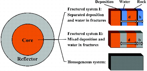
shows the schematic of the MCNP model, in which the spherical core is filled with one of the three different geometries (shown right), surrounded by the one-meter-thick rock as reflector. The reflector is “infinitely” thick for neutrons, so that no neutron leakage could occur. Two types of heterogeneous cores and one type of the homogeneous core are considered. The heterogeneous cores consist of layered plates. In fractured geometry I, the core is filled with layers of rock (in orange), heavy metal depositions (in black), and water (in blue) alternately. The geometry of the fracture is characterized by aperture b, and pitch distance d between two adjacent fractures. The fractured system II is the same as the fractured system I, except that the heavy metal deposition layer and the water layer are homogenized into one phase. In the homogeneous system all the three materials are homogenized.
The combination of rock, water, and heavy metal is expressed by two independent variables: void volume fraction (VVF) and heavy metal volume fraction (HMVF). For the heterogeneous systems, the VVF is given by b/d, representing the averaged fracture volume fraction, or the fracture porosity in rock. For the homogeneous system, VVF represents the void space fraction that is filled with water and heavy metal precipitations, equivalent to the porosity of a porous rock. The HMVF is defined in a similar way, representing the volume fraction of heavy metal precipitations in the entire core. The volume fraction of the solid-phase of the rock then equals to (1-VVF), and the water volume fraction is given by (VVF–HMVF). By definition, the HMVF must be smaller than VVF, because the volume of precipitation cannot exceed the available void space in the rock.
Once the VVF and HMVF are given, the number densities of each nuclide species for MCNP calculation can be estimated by densities given in the materials input for each region. The radius of the core is determined by the total heavy metal mass and HMVF. The reflector is fixed to one meter thick, and consists of the same type of rock.
In order to perform the parametric study, an MCNP-input-file generator has been newly developed to combine the materials and geometry input parameters, and the output of ORIGEN calculations into MCNP input file. For given compositions and geometry for rock and heavy metal, calculations have been first performed for various VVF and HMVF parameters, assuming that the mass of heavy metal in the core is 250 MT. The discrete keff results have been used to generate a keff contour plot by interpolation. By defining a nominal sub-criticality criterion keff < 0.98, the super-critical region can be determined in the parametric space. Within the super-critical parameter range, MCNP calculations have been conducted to obtain the critical mass of heavy metal deposition.
4. Input data
4.1. heavy metal compositions
The burnup calculations based on the detailed Fukushima Daiichi reactor operation schedule and corrected average thermal power are given by Ref. [Citation1]. We also made independent calculations for comparison by the ORIGEN code but with different data libraries. Reference [Citation1] used the cross section libraries developed specifically for the crippled reactors, while we have used standard libraries for boiling water reactor (BWR). Some difference has been observed in the mass ratio between the U-235/Pu-239, but the total mass (U-235 + Pu-239) agrees well.
The results in Ref. [Citation1] are considered more accurate. Therefore, in this study, heavy metal compositions given by Ref. [Citation1] have been utilized. The heavy metal compositions at the accident time are summarized in . Isotopes with weight fraction below 0.01% are not shown.
Table 1. Heavy metal compositions at the time of the accident.
The heavy metal compositions after 200,000 years are tabulated in . These compositions have been used as the input for the MCNP calculations. In this case, only 3.7 kg of Pu-239 remains but the enrichment of U-235 increases from 1.81% to 2.25%. The heavy metal precipitations are assumed to be UO2 and PuO2, with densities 10.97 and 11.50 g/cm3 [Citation22].
Table 2. Heavy metal compositions after 200,000 years of decay.
4.2. Compositions of rock and groundwater
Observation at the Oklo natural reactors [Citation23] indicates that the highest grade uranium ore in sandstone always coexists with hematite and illite [Citation24]. Thus, iron-rich minerals in the rock play crucial roles in both transport and neutronics aspects. Uranium precipitations are usually close to iron-rich minerals in the rock. Iron is also a strong neutron-absorber that will decrease the neutron multiplicity.
Based on these observations, two types of host rocks () are considered in this study: average sandstone and magnetite-hematite-bearing pelitic gneiss containing 15% iron. The chemical compositions are given in Ref.[Citation25], where the crystallized water in the rock is also included. The grain densities are calculated based on the normative compositions, and the porosities of the rock are considered in the range from 0% to 30%.
Table 3. Host rock compositions.
Groundwater is assumed to consist of H2O with density 1 g/cm3, and soluble neutron absorbers such as chlorine are neglected for conservatism. For each kind of rock, homogeneous and heterogeneous geometries are considered (see ). For the heterogeneous systems, the fracture aperture takes values of 0.1, 0.2, 0.5, 1.0, 2.0, 3.0, 4.0, 5.0, and 10.0 cm. In the fractured geometry, a few percent crystallized water existing in the host rock is included (see ).
5. Numerical results
5.1. Effective neutron multiplication factor, keff
The numerical results for the effective neutron multiplication factor keff for the deposition containing 250 MT of uranium with the composition shown in are first discussed in this section. Calculations have been made for combinations of two rock types (sandstone and iron-rich rock) as shown in , and three geometries as shown in .
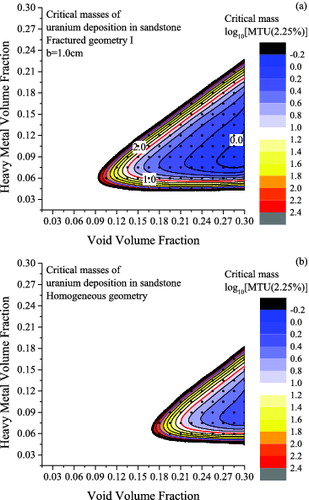
(a) and 2(b) shows the contour plots of keff for fractured geometry I with b = 1.0 cm for the sandstone and for the iron-rich rock, respectively. Black dots represent points at which MCNP computations have been performed. Contour lines have been drawn by interpolation among the nearest dots. The contour line in red color, referred to as the critical contour line hereafter, indicates the nominal criticality criterion, keff = 0.98. The triangular region results from the fact that the HMVF cannot be greater than VVF. In either case of rock, the keff value tends to be greater for a greater value of VVF (i.e. to the right along the horizontal axis). A maximum keff is observed as HMVF increases for a fixed VVF.
Figure 2. (a) keff contour plot for fractured sandstone with fractured geometry I. (b) keff contour plot for iron-rich rock with fractured geometry I.
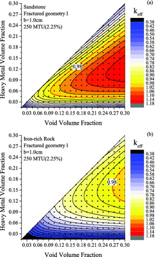
These general tendencies can be explained by the amount of water in the system. Fission neutrons have greater chance to be thermalized with greater amount of water. More detailed discussions on the criticality mechanisms are given in Section 6. If the VVF is 0.094 or smaller for sandstone ( (a)) and 0.265 for iron-rich rock ( (b)), then the uranium deposition with enrichment of 2.25% in fractured geometry I is always sub-critical. We call this threshold VVF as the minimum critical VVF hereafter. The comparison between sandstone and iron-rich rock shows importance of rock compositions. For the iron-rich rock, the likelihood of criticality event would be significantly smaller because iron strongly absorbs neutron.
The minimum critical VVF can be found similarly for every combination of rock type, geometry, and a certain mass of uranium deposition. The results are summarized in , where the minimum critical VVF versus fracture aperture b for different rock types and geometries are plotted for 250 MT of uranium deposition. The solid lines represent the minimum critical VVF for sandstone and the dashed lines for the iron-rich rock, respectively. Because the homogeneous geometry has no dependence on b, the red horizontal line shows the results. The minimum critical VVF for the combination of the iron-rich rock and homogeneous geometry is not shown in the figure, because the system remains sub-critical when VVF < 0.3.
Figure 3. Minimum VVF for keff > 0.98 for different rocks and geometries, assuming all 250 MT of uranium is deposited.
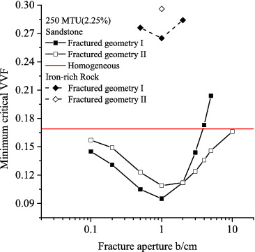
For both rock types with fractured I geometry, the minimum critical VVF becomes the smallest at aperture b = 1.0 cm. For sandstone, in the range of b < 2.0 cm, the minimum critical VVF for fractured geometry I is smaller than that for fractured geometry II. Conversely, in the range of b > 2.0 cm, the minimum critical VVF for fractured geometry II is smaller than that for fractured geometry I. This result indicates that heterogeneity of the uranium deposition has sensitive effects on neutron transport. Detailed discussions on effects of heterogeneity and fracture apertures will be given in Section 6.2. For iron-rich rock, the minimum critical VVF is much greater than that for sandstone.
Similar tendencies were observed when considering the multiplication factor keff for different geometries with various fixed VVF values. For example, shows the keff as a function of fracture aperture b for the three geometries shown in . For all the geometries, the VVF is fixed at 0.24, while the HMVF is chosen to optimize the multiplication. For both types of rocks, in the small-b region, the keff decreases in the order of fractured geometry I, fractured geometry II, and homogeneous geometry. Both fractured geometries approach the homogeneous system when b approaches 0, because the heterogeneity of fractured systems vanishes when the fracture aperture is much smaller than thermal neutron mean free path.
Figure 4. keff for different rock types and heterogeneous geometries with different fracture apertures.
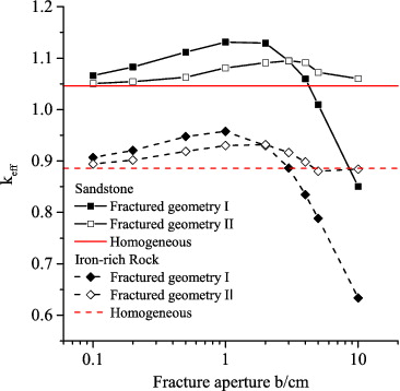
The keff starts to decrease for both fractured systems when b is larger than several centimeters. The keff for fractured geometry I decreases much more sharply than fractured II, and eventually falls far below the homogeneous keff. Detailed discussions on this behavior at large b are given in Section 6.2.
5.2. Critical mass
By reducing the mass of uranium deposit within the super-critical parameter range while fixing the geometry, the critical masses can be calculated. For fractured geometry I, the value of fracture aperture b is fixed at 1.0 cm as the reference value for the critical mass calculations.
(a) and 5(b) shows the contour plots for the critical mass for sandstone comparing two geometries as indicated within the figures. The boundary of the plot is extracted from the red contour line from the keff results ( (a) and 2(b)). The values for critical masses are shown in a logarithm scale in units of MT of uranium, and the contour lines for 1, 10, and 100 MT are shown in black, red, and blue, respectively.
Figure 5. (a) Critical mass contour plot for fractured sandstone. The values in the figure and in the side-bar scale are logarithm of MT of uranium included in the system. (b) Critical mass contour plot for homogeneous sandstone. The values in the figure and in the side-bar scale are logarithm of MT of uranium included in the system.
It is interesting to note that more than 700 MT of uranium with the enrichment of about 3.7% was involved in the sustainable chain reactions in reactor zones 1–6 of Oklo uranium deposit [Citation21]. The highest grade uranium ore found in Oklo contains up to 15% of uranium by weight, which can be converted into the HMVF by assuming dry sandstone as 0.047.FootnoteWith this value of HMVF, the results shown in (b) indicate that 100 MT of uranium deposited homogeneously in the sandstone can become critical.
This comparison of the results in with the Oklo phenomenon implies that uranium deposition with a mass of the order of a few hundred tons could actually exist in natural geological environment, and that a uranium deposition with the mass in the range between fractions of MT to a few hundred MT can become critical dependent on rock types, geometries, and uranium enrichment. Thus, we cannot exclude the possibility of critical configurations to occur in the far field originating from damaged fuel simply by the neutronics analysis.
In order to summarize the influence of various conditions on criticality, the minimum critical VVF for different rock types, geometries, and masses of uranium deposition are tabulated in . The rock type has prominent influence on criticality due to the neutron-absorbing constituents.
Table 4. Minimum critical void volume fractions (VVF) for various combinations of geometries and uranium deposition masses.
Observing each (horizontal) row individually, for any combination of rock and geometry, the minimum critical VVF decreases, as mass of uranium deposition increases, indicating that with greater mass of uranium included, the criticality is achieved in a wider range of rock porosity. Comparing different rock types with fixed geometry (fractured geometry I; see rows 1 and 3), for different uranium deposition masses, the minimum critical VVF for the iron-rich rock is always larger than the sandstone by approximately 0.17. Then, comparing different geometries for the sandstone systems (see rows 1 and 2), the minimum critical VVF for fractured geometry I for sandstone is around 0.07 smaller than that for homogeneous geometry for different masses of uranium deposition.
It is observed that the uranium mass has significant influence only in a small mass range. The decrement of minimum critical VVF is decreasing as the mass of uranium deposition is getting larger. The minimum critical VVF is decreased by 0.01 when the deposition mass is increased from 100 to 250 MT, while the minimum critical VVF is decreased by 0.1 from 1 to 10 MT. This is because with greater mass of the deposition, the neutron leakage is getting lower, which makes the system approaching an “infinite” system in terms of neutron leakage. Consequently, the keff will be more determined by the composition instead of its size, which is almost equal to kinf, and almost independent of the mass or size of the uranium deposition.
In summary, the systems keff will increase, when (1) the rock contains fewer neutrons absorbing materials, (2) the rock has larger porosity, (3) the deposition has heterogeneous geometry, and (4) the deposition contains larger amount of uranium.
6. Discussions
6.1. Influences of uranium mass
For a fixed VVF, there is the HMVF that gives the maximum keff because the void volume is filled with the uranium deposition and water (see ). For the fractured geometry I (), these are expressed by the layer thickness of respective materials. With increase in the layer thickness of HMVF, the thermal neutron absorption in the uranium deposition increases, while the thermal neutron flux decreases because the moderation decreases. These two competing effects result in the maximum HMVF for a fixed VVF. For example, for sandstone with b = 1.0 cm and VVF = 0.24, the maximum keff occurs at HMVF ∼0.12, or the H/U-235 number density ratio ∼120. Compared with the homogeneous uranium-water system, for which the optimized H/U-235 ratio is about 300 [Citation18], it is smaller because the rock provides additional moderation.
In the keff calculations, the total mass of uranium is fixed with 250 MT; the radius of the core is determined in such a way that 250 MT of TFM is accommodated with the given value of HMVF. Therefore, the neutron leakage is also influenced by HMVF. This effect is considered less important, however, because the core radius is usually as large as several meters, and well reflected.
6.2. Influences of different geometries
The influences of different geometries can be semi-quantitatively explained by expressing the infinite multiplication factor of different systems by the four-factor formula [Citation26]
(1)
(1)
where p is the resonance escape probability, f is the thermal utilization factor, ϵ is the fast fission factor, and η is the thermal reproduction factor. To simplify the discussion, the comparison is made only between fractured I and the homogeneous systems, and to adopt the convention of neutronics analysis for reactors, in the discussion hereafter, the uranium deposition is referred to as the fuel, and the water and rock as the moderator.
Generally speaking, the resonance escape probability p of heterogeneous systems is larger than that of a homogeneous system, due to two major effects [Citation26]. First, the separation of moderator and fuel allows some neutrons to slow down without contacting the fuel, and second, the outer layer of the fuel shields the inner layer from resonance energy neutrons, or the so-called self-shielding effect. For the fractured geometry I, the first effect is more important in the small b region. However, with increasing fracture aperture, the thickness of the fuel layer increases to keep the same HMVF. As a result, the self-shielding effect becomes more prominent.
For the heterogeneous system consisting of uranium, water, and rock, the thermal utilization factor f is given by
(2)
(2)
where , VX, and
are the averaged macroscopic thermal absorption cross section, volume, and averaged thermal flux of fuel (X = F) or moderator (X = M) [Citation26], respectively. Recall the definition of VVF and HMVF, and define the thermal disadvantage factor as the ratio between the averaged thermal flux in the moderator and the fuel
(3)
(3)
Then, the thermal utilization factor of a heterogeneous system can be written as
(4)
(4)
By averaging the number densities of materials in fuel and moderator, the thermal utilization factor after the fully homogenization of the heterogeneous system can be given in a similar way:
(5)
(5)
Again, due to the self-shielding effect, the thermal flux tends to be depressed in the highly absorbing fuel region. Thermal disadvantage factor ζ is usually greater than unity, and increases with the thickness of fuel layer due to stronger self-shielding. Comparing Equations (4) with (5), the thermal utilization factor becomes greater after homogenization, and decreases with increasing b.
The aforementioned discussion can be further demonstrated by numerical results. The thermal disadvantage factor of the fractured geometry I for sandstone with VVF = 0.24 and HMVF = 0.12 has been calculated by MCNP, as shown in . The result is given by the ratio between the averaged thermal fluxes tallied in the moderator layer (water + rock) and fuel layer (heavy metal depositions) that are located in at the center of the core. Because the VVF and HMVF are fixed, the thickness of uranium deposition increases proportional to the fracture aperture b. When b is greater than 2 cm, the inner part of the fuel is depleted of thermal flux due to spatial self-shielding. If the thickness of the fuel layer continues to increase, the averaged thermal flux in the fuel region will decrease rapidly. Therefore, the thermal disadvantage factor ζ increases sharply when b is greater than 2 cm. The contribution to the decrease of the thermal utilization factor f overcomes the increase of resonance escape probability p, corresponding to the sharp decrease of keff in .
Figure 6. Thermal disadvantage factor, fast fission factor, and thermal reproduction factor for different fracture apertures for fractured system I.
The influences of fast fission factor ϵ and thermal reproduction factor η are also evaluated by MCNP calculations and shown in in a similar way. When b increases from 0.1 to 10 cm, the fast fission factor ϵ decreases from 1.22 to 1.06 cm. The thermal reproduction factor η is not sensitive to the change in fracture aperture. In all calculations its value is always 1.76.
To summarize the discussions in this section, for the fractured geometry I with increasing fracture apertures, the neutron multiplication is determined by the net effect of increasing resonance escape probability p, decreasing thermal utilization factor f and decreasing fast fission factor ϵ. For the fractured geometry II, because the fuel and moderator are only mixed in the fracture region, the system behaves somewhere between the fractured I and homogeneous systems. Compared with fractured I, by mixing fuel and water, both resonance and thermal neutron self-shielding become weaker in fractured geometry II. The net effect is that the keff of fractured geometry II is smaller than fractured I when b is small, and the situation is reversed when b is large as shown in .
6.3. Influences of rock compositions
The influence of different rock types could also be explained by Equation (4). The rock with stronger neutron absorption will have larger value of the denominator of Equation (4), resulting in smaller f and smaller keff. Another effect is the increased ζ for large b will be amplified by the term For the rock with stronger neutron absorption, the keff will start to decrease at smaller fracture aperture. For example, the optimized b for sandstone is 1 and 2 cm, but for iron-rich rock is 1 cm, as shown in .
7. Conclusion
To investigate whether critical configurations are conceivable when damaged fuel from Fukushima Daiichi reactors is disposed of in a geological repository, neutronics analysis has been performed in this study.
Event sequence toward formation of possible critical configurations has been developed based on the understanding of uranium and plutonium behaviors in geological formations, which resulted in focusing on the uranium deposition scenario in the far-field region with a low enrichment of 2.25%. The analysis has been made for two kinds of rocks by considering a finite system with three different geometries, containing various masses of uranium. The three different geometries include heterogeneous (fractured I and II) and homogeneous systems. The exploration was performed to find optimized combinations of geometry, fracture aperture and the model parameter HMVF, to give the minimum rock porosity (VVF) for criticality. The influences of geometries have been further discussed semi-quantitatively, in which the self-shielding effect is found to be the most important mechanism.
After the present analysis, we conclude that various far-field critical configurations are conceivable for given conditions of materials and geological formations. Whether any of such critical configurations would occur in actual geological conditions remains unanswered. To answer this question, we need to extend this study in the following directions. First, from the neutronics point of view, a more “realistic” fractured system with both the fracture orientation and size randomly distributed is suggested. It is observed in this study, that the difference between the homogeneous and heterogeneous geometries could result in around 0.07 differences in the minimal critical porosity considering regularly fractured for the heterogeneous geometries. However, it is still an open question whether a randomly fractured system is enveloped by the homogeneous and regularly fractured systems.
Second, we need to perform the mass transport analysis to explore whether such a configuration obtained by neutronics analysis is likely to be occurred in geological formations. In order to make meaningful analysis along this direction of studies, however, detailed information about geological formations, geohydrology, and geochemistry is required, which can only be obtained after determining a disposal site. If a repository site is given, as demonstrated for the YMR, the possibility of criticality event to happen can be thoroughly investigated, and if necessary, engineering measures to eliminate such possibility can be considered.
Third, prior to knowing the site location, it is still useful to conduct a generic mass transport analysis. Combining the mass transport analysis with the results of the neutronics analysis, which has been performed partially in this study, some important points for selecting a site for criticality safety can be suggested. These include (1) iron existing in the host rock reduces the likelihood of criticality significantly; (2) low host rock porosity is preferred for criticality safety; (3) the conservatism could change when comparing heterogeneous geometries for different fracture apertures, in other words, the planar fracture geometry applied in the previous CSA for geological disposal [Citation6–11,Citation15] would not necessarily yield conservative results against the homogeneous uranium deposition because the keff for heterogeneous geometry can be smaller than that for homogeneous one in case of larger width of fracture aperture; and (4) the importance of the mass of the deposition increases when it is smaller. To make these more reliable and specific, further studies in the neutronics and mass transport are crucially important.
Acknowledgements
We would like to thank JAEA, Nuclear Safety Research Center, for providing us with the results of ORIGEN calculation [Citation1]. This study was carried out under a contract with METI (Ministry of Economy, Trade and Industry) of Japanese Government in the fiscal year of 2012 as part of its R&D supporting program for developing geological disposal technology.
Notes
1. The HMVF can be calculated as follows:
References
- Nishihara K, Iwamoto H, Suyama K. Estimation of fuel compositions in Fukushima-Daiichi nuclear power plant ( Report No.: JAEA-Data/Code 2012-018). Tokai (Japan): Japan Atomic Energy Agency; 2012.
- USDOE OCRWM. Screening analysis of criticality features, events, and processes for license application ( Report No.: ANL-DS0-NU-000001 REV 00). Washington, DC: Sandia National Laboratories, OCRWM Lead Laboratory for Repository Systems; 2008.
- Hicks TW, Rudge AJ. Revision of the general criticality safety assessment. Oakham (UK): Galson Science Ltd.; 2007.
- Geochemistry model validation report: external accumulation model ( Report No.: ANL-EBS-GS-000002 REV 01). Las Vegas: Bechtel SAIC Company, LLC; 2006.
- Geochemistry model validation report: external accumulation model ( Report No.: ANL-EBS-GS-000002 REV 01 AD 01). Las Vegas: Bechtel SAIC Company, LLC;2007
- Kastenberg WE, Peterson PF, Ahn J, Burch J, Casher G, Chambré PL, Greenspan E, Olander DR, Vujic JL, Bessinger B, Cook NGW, Doyle FM, Hilbert LB, Jr. Considerations of autocatalytic criticality of fissile materials in geologic repositories. Nucl Technol. 1996;115:298–310.
- Rechard RP, Sanchez LC, Trellue HR. Consideration of nuclear criticality when directly disposing highly enriched spent nuclear fuel in unsaturated Tuff – I: nuclear criticality constraints. Nucl Technol. 2003; 144:201–221.
- Rechard RP, Sanchez LC, Trellue HR. Consideration of nuclear criticality when directly disposing highly enriched spent nuclear fuel in unsaturated Tuff – II: geochemical constraints. Nucl Technol. 2003; 144:222–251.
- Ahn J. Criticality safety assessment for a conceptual high-level-waste repository in water-saturated geologic media. Nucl Technol. 1999;126:303–318.
- Greenspan E, Vujic J, Burch J. Neutronic analysis of critical configurations in geologic repositories – I: weapons-grade plutonium. Nucl Sci Eng. 1997;127:262–291.
- Vujic J, Greenspan E. Neutronic analysis of critical configurations in geologic repositories – II: highly enriched uranium. Nucl Sci Eng. 1998;129:1–14.
- Kienzler B, Loida A, Maschek W, Rineiski A. Mobility and criticality of plutonium in a repository. Nucl Technol. 2003;143:309–321.
- Sanchez R, Myers W, Hayes D, Kimpland R, Jaegers P, Paternoster R, Rojas S, Anderson R, Stratton W. Criticality characteristics of mixtures of plutonium, silicon dioxide, nevada Tuff, and water. Nuc Sci Eng. 1998;129:187–194.
- Pelowitz DB. MCNP6TM user's manual (draft) ( Report No.: LA-CP-11-01708). Los Alamos: Los Alamos National Laboratory; 2011.
- Ahn J. Transport of weapon-grade plutonium and boron through fractured geologic media. Nucl Technol. 1997;117:316–328.
- Kienzler B, Vejmelka P, Römer J, Schild D. Actinide migration in fractures of granite host rock: laboratory and in situ investigations. Nucl Technol. 2009;165:223–240.
- Williams DS, Rommel JC, Murray RL. An overview of nuclear criticality safety analyses performed to support Three Mile Island unit 2 defueling. Nucl Technol. 1989;87:1134–1144.
- Paxton HC, Pruvost NL. Critical dimensions of systems containing 235U, 239Pu, and 233U ( Report No.: LA-10860-MS). Los Alamos: Los Alamos National Laboratory; 1987.
- Lemaître-Xavier E, Ahn J. Criticality safety for plutonium-filled canister in a repository[ CD-ROM]. In: McMahon K, Butterfield Month B, editors. Proceeding of GLOBAL 2013; 2013 Apr 28–May 2; Salt Lake City: American Nuclear Society; 2013.
- World distribution of uranium deposits (UDEPO) with uranium deposit classification ( Report No.: IAEA-TECDOC-1629). Vienna (Austria): International Atomic Energy Agency; 2009.
- Gauthier-Lafaye F, Weber F. The francevillian (lower proterozoic) uranium ore deposits of gabon. Econ Geol. 1989;84:2267–2285.
- Aylward GH, Findlay TJV, Findlay T, Aylward G. SI chemical data. 4th ed. New York, NY: John Wiley & Sons, Inc.; 1999.
- Gauthier-Lafaye F, Holliger P, Blanc PL. Natural fission reactors in the Franceville basin, gabon: a review of the conditions and results of a “critical event” in a geologic system. Geochim Cosmochim Acta. 1996;60:4831–4852.
- Gauthier-Lafaye F, Weber F. Natural nuclear fission reactors: time constraints for occurrence, and their relation to uranium and manganese deposits and to the evolution of the atmosphere. Precambrian Res. 2003;120:81–100.
- Angenheister G, editor. Numerical data and functional relationships in science and technology: group V geophysics. Vol. 1A. Berlin (Germany): Springer; 1982.
- Duderstadt JJ, Hamilton LJ. Nuclear reactor analysis. New York, NY: John Wiley & Sons, Inc.; 1976.