
 ?Mathematical formulae have been encoded as MathML and are displayed in this HTML version using MathJax in order to improve their display. Uncheck the box to turn MathJax off. This feature requires Javascript. Click on a formula to zoom.
Abstract
Penetration behavior of radionuclides such as 137Cs into dried concrete material, dried mortar material and epoxy paint for a few dozen days was observed using a solution containing fission products extracted from irradiated fuels to obtain fundamental information on the radionuclide penetration rate and depth. Hardly any radionuclides could penetrate into the epoxy paint. The radionuclide solution penetrated into concrete and mortar materials to a depth of a few millimeters for a few dozen days. The penetration behavior observed near the surface of concrete and mortar materials was similar to the diffusion of nuclides in media such as water-saturated concrete, bentonite and cement materials.
1. Introduction
In the March 2011 accident at the Fukushima Daiichi Nuclear Power Plant, radionuclides such as 137Cs and 134Cs produced in the reactor cores were released to both the environment and interior areas of the reactor building. The reactor building interior areas remain highly contaminated [Citation1], and the high air dose rates within them do not permit persons to enter into them without taking decontamination and/or shielding measures. However, in order to proceed with the government's reactor decommissioning project [Citation2], some workmen will have to enter the reactor buildings while keeping their individual exposure at the admissible dose limit.
As the first step, the reactor building interiors must be decontaminated by remotely controlled decontaminating methods, especially the floors and the walls. To carry out this work, it is necessary to know the contamination aspects, such as the contamination depth, kinds of contaminating species and their adhesion patterns, in as much detail as possible. This information will support the development of decontamination methods and plans. Therefore, Japan Atomic Energy Agency workers [Citation3] are measuring the kinds of radionuclides and their activities on concrete core samples removed from the reactor building floors within the decommissioning project.
Most of the floors in the Fukushima Daiichi Nuclear Power Plant were coated with epoxy paint which has a property that prevents water penetration. Therefore, wherever the epoxy paint had been used, contamination should not have been penetrating into the concrete materials underneath the paint. However, wherever the epoxy paint coatings have been damaged and exposed to contaminated water, there is a potential for contamination penetration into the concrete materials. In this case, the water containing the radioactive nuclides will penetrate into the dry concrete materials. It is necessary to confirm the potential of epoxy paint for preventing of the penetration, and understand the contamination penetration behavior of dried concrete materials to develop future decontamination techniques for deep radionuclide penetration.
In the field of geological disposal of high-level radioactive wastes, migration behavior of medium- and long-lived radionuclides from the wastes to the environment has been studied by a number of researchers. Studies have generally focused on the diffusion behavior of radionuclides in water-saturated materials such as mortar, concrete and other buffering materials [Citation4,5]. Research on the penetration mechanism of radionuclides in dried concrete materials has rarely been conducted, although the diffusion behavior of tritium water into dried cements materials has been studied for evaluation of the material suitability and safety for fusion reactor structures [Citation6].
In this study, we conducted penetration tests to observe how a water solution including radionuclides penetrates into epoxy paint, dried concrete material and mortar material. Specimens of epoxy paint, concrete material and mortar material were left in contact with the solution to simulate a hot spot condition for a maximum of 58 days. The solution was extracted from irradiated fuels and included other radionuclide besides 137Cs; this was to allow observation of different penetration behavior for each radionuclide. Under these limited conditions such as periods, materials and radionuclides, we obtained fundamental information on the penetration rate and depth which will be used to evaluate decontamination methods for epoxy paint and dried concrete/mortar materials.
2. Experimental
2.1. Concrete material specimens and the radionuclide water solution
In order to simulate the conditions for dried concrete materials used in old plants, we obtained aged concrete material from the walls of Reprocessing Test Facility of the former Japan Atomic Energy Research Institute which was constructed in 1967 [Citation7]. In addition, we prepared dried mortar material for the comparison (difference of aggregate fraction and arrangement); this material was manufactured in 2012 and its density is approximately 2.1 g/cm3. The mortar material specifications are shown in . Both concrete and mortar materials were confirmed to contain less than 3% water; this was determined by heating them at 378 K in a reduced pressure chamber for 8 hours. Epoxy paint (Eponix#3100, Dai Nippon Toryou) was substituted for the epoxy paint coating material. Four types of specimens were prepared for the penetration tests: epoxy paint only; concrete material; mortar material; and fixing epoxy resin only as a reference specimen (see ).
Table 1. Specifications of the mortar material.
Figure 1. Penetration test apparatus (type 1).
The main radionuclide contributing to environment contamination is 137Cs, but other radionuclides were also included as targets in the water solution preparation for comparison by using fuel pellets irradiated to 43.0 MWd/kg (its cooling time is more than 20 years) in the Advanced Thermal Reactor, FUGEN [Citation8]. Irradiated fuel pellets were dissolved in 8 mol/dm3 HNO3 solution by heating for 4 to 6 hours with a few drops of HF. The solution was passed through a 0.2-μm membrane filter to remove the residue remaining in the solution. By adding 31% H2O2 and 16 mol/dm3 HNO3 solution into the filtered solution, Pu (VI) was converted to Pu (IV). After this, the solution was taken to dryness by heating; the solid material was dissolved into 8 mol/dm3 HNO3 solution, and then loaded onto an anion exchange resin column (AG 1-×4 200-400 mesh size, BIO-RAD). Pu and U ions in this solution could be trapped on the resin. The other ions were eluted from the resin column using 8 mol/dm3 HNO3 solution. γ-ray emitting radionuclides in the eluate were analyzed by a high purity Ge semiconductor detector (GMX20 P2, ORTEC), and qualitatively evaluated as shown in . These γ -ray emitter radionuclides included 241Am, 134Cs, 137Cs, 154Eu and 155Eu. These nuclide concentrations are so small in the solution that coexisting nuclides are not thought to be influential each other in penetration behavior. The fuel pellets used to prepare the solution had been stored for long term; therefore, the amounts of most of the middle and short life radionuclides had been reduced to quantities that did not affect the radioactivity measurements.
Table 2. Concentrations of γ-ray emitting radionuclides in the solution extracted from irradiated fuel pellets.
2.2. Penetration tests
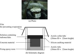
Penetration tests were conducted with the apparatus (type 1) shown in . The concrete and epoxy paint specimens were cut into sizes of 15 mm×15 mm× 15 mm thick and 15 mm×15 mm×3 mm thick, respectively. They were fixed into acrylic tubes (28 mm ID×22 mm height) with a fixing epoxy resin. As the reference specimen, only fixing epoxy resin was filled into an acrylic tube. While the fixing epoxy resin was solidifying, the specimen-containing acrylic tubes were kept in a reduced pressure chamber to remove bubbles in the fixing epoxy resin. An acrylic collar tube was attached on the top of the specimen-containing acrylic tube using silicon caulking material, and then 2 mL of the solution containing radionuclide was poured onto the specimen. In order to prevent evaporation of the solution, a plastic paraffin film was wrapped over the top of the acrylic collar tube. These penetration test apparatuses were set in a glove box at room temperature for 3, 16 and 58 days.
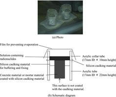
The apparatus described above has a structure in which the bottom of a concrete specimen is enclosed by the fixing epoxy resin. In addition, the specimen is restrained by the hardened fixing epoxy resin. The former may disturb penetration behavior by enclosing (i.e. covering) the bottom surface of the specimen. The latter can inhibit expansion of the specimen due to absorption of the solution. If the expansion is related to the path width, this may affect the penetration behavior. Therefore, another penetration test apparatus (type 2) was prepared for confirming these two points and it is shown in . Additionally, this apparatus was utilized for the mortar specimen testing. Consequently, using this apparatus, we confirmed the effects of enclosing the bottom and restricting expansion of the specimens, and we tried to detect the apparent difference between the concrete and mortar materials also.
Figure 2. Penetration test apparatus for confirmation (type 2).
The test conditions using the two apparatuses in type 1 and type 2 are summarized in .
Table 3. Test matrix of conditions: apparatus, period and material.
2.3. Analyses of penetration behavior
After the desired period for penetration had ended, the remaining solution and the acrylic collar tube were removed to allow the specimens to dry for one day in the glove box at room temperature. Dose rates on the penetration surface were measured with a dosimeter (AE-133, Applied Engineering Inc.) through a polyvinyl chloride sheet. A two-dimensional dose rate distribution on the penetration surface was obtained with an imaging plate (BAS IP SR-2040 E, General Electric Co.). These measurements were conducted every time the specimen was sectioned by grinding (0.3 – 0.5 mm thickness/one time grinding) the penetration surface with abrasive papers (#120 for concrete and mortar specimens, #180 for epoxy paint specimens). The powder obtained during grinding was stored into a 5-mL vial, and was prepared as a sample for γ-ray spectrometry with the detector mentioned above. Each concentration of radionuclide was evaluated in the unit of μg/mg of the powder.
3. Results
3.1. Penetration profiles
For all the reference specimens (fixing epoxy resin), the radioactive species only adhered onto the surfaces and did not penetrate into the resin. This implies that there was no effect from fixing epoxy resin on the penetration profiles obtained for the other specimen tests.
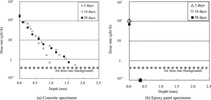
(a) and (b) shows dose rate profiles in the depth direction of concrete and epoxy paint specimens, respectively, obtained using the type 1 apparatus. In the epoxy paint specimens ((b)), the dose rate for every penetration period was equivalent to the air dose rate (background) except for the surface without grinding. The depth was approximately 0.4 mm per one grinding; therefore, the solution could hardly penetrate into the epoxy paint. On the other hand, the penetration profiles for the concrete specimens ((a)) showed that the dissolved radionuclides could penetrate into them. However, the dose rate could be lowered to the air dose rate (background) by 1.0–2.0 mm grinding. The radionuclide penetration proceeded with time.
Figure 3. Penetration profiles of concrete and epoxy specimens for 3, 16 and 58 days (the dose rates were measured after every grinding).
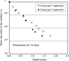
In order to confirm the effects of open or enclosed bottom surfaces and restriction of specimen expansion by the fixing epoxy resin on penetration in the concrete material, the penetration behavior was observed using the type 2 apparatus for confirmation. The comparison for 16 days is shown in for both type 1 and type 2 apparatuses. The dose rates were normalized in this graph since the specimen sizes differed. Very little difference was apparent for the apparatuses; therefore, the effects of open or enclosed bottom surfaces and restriction of expansion by the fixing resin were too small to prevent the penetration. As well, the difference of profiles below 1 mm depth is caused by shimmering of the background; here the data near the surface are meaningful.
Figure 4. Comparison of penetration profiles in concrete specimens obtained using type 1 and type 2 apparatuses.
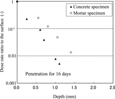
Both penetration behavior into the concrete specimen and the mortar specimen are compared in , in which the type 2 apparatus was utilized. The profiles indicated that the radionuclides could penetrate into the mortar specimen somewhat easier than into the concrete specimen. This reason was tied to understanding the results of the imaging plate measurement mentioned in Section 3.2.
Figure 5. Comparison of penetration profiles between the concrete specimens and the mortar specimens.
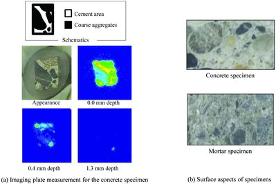
3.2. Imaging plate measurement
The imaging plate measurement describes the path of radionuclides during penetration. (a) plots the distribution of dose rate for the concrete specimen. As seen in this figure, the intensity for the coarse aggregates was lower than in the cement area. The radionuclides could mainly penetrate the concrete materials via the cement area. The penetration rate depended on the path width that is, the cross-sectional area of the cement, therefore the penetration in the mortar specimen which had a large cement area and fine aggregates proceeded earlier than in the concrete specimen shown in (b). However, this tendency is not true for the other researchers’ similar experiments [Citation9], in which they prepared concrete specimens from the same raw material by different cross-sectional area of cement. From this discrepancy, it is difficult to compare, directly and quantitatively, the profiles for concrete specimens with those for mortar specimens. The difference is thought to be caused by differences of specimen structure such as pore and fissure density.
Figure 6. Example imaging plate measurement of the concrete specimen and the surface aspects of concrete and mortar specimens. The colors indicate decreasing intensity of dose in the order of red > yellow > green > blue.
3.3. γ-ray spectrometry of the powder obtained during grinding
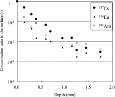
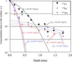
Normalized concentration profiles for 137Cs, 154Eu and 241Am in the depth direction of the concrete specimen are shown in (for 16 days). The concentration of 137Cs decreased more gradually along the depth direction than those of 154Eu and 241Am. However, all the profiles below 0.5–1.0 mm in depth had a similar gradual slope that was not like the slope near the surface. Generally Cs, Eu and Am in water solution are ions such as Cs+, Eu3+ and Am3+. These ions have different adsorption and desorption properties on the surface of water-saturated path [Citation10]. In addition, diffusion coefficients for these ions in free water differ from each other [Citation11]. According to the literature [Citation10,11], the apparent diffusion coefficient of Cs in water-saturated mortar materials is generally higher than that of Am or Eu, which is in good agreement with our results.
Figure 7. 134Cs, 137Cs, 154Eu and 241Am concentration profiles of the concrete specimen (16 days).
It appeared that the penetration mechanism depended on each ion's properties near the surface and the other conditions such as fissures aspects for the deep region.
4. Discussion
The penetration mechanism into the dried concrete and mortar materials is discussed here.
When the penetration mechanism of nuclides into dried concrete and mortar materials is treated, two migration processes must be taken into consideration. The first one is the advection current process of solution and the other is the diffusion process. Generally, to describe penetration, an advection–diffusion equation is used as follows:
(1)
(1) where Cm (e.g. g/m3) is the average concentration of a nuclide, t (s) is the time, x (m) is the distance from the surface along the penetration direction, Da (m2/s) is the apparent diffusion coefficients in porous medium, and u (m/s) is the advection flow velocity of solution. However, u for general concrete and mortar materials is quite large and concrete and mortar with a thickness of 4 cm will become filled with the solution within a day according to a literature [Citation12].
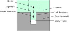
As other analysis methods for penetration of solution into porous medium, it is possible to use Darcy's law, the Lucas–Washburn equation or the force balance model for gravity, capillary and internal pressure forces shown in . However, these could not describe the penetration behavior in this study since the penetration profiles obtained in this study does not have a penetration limitation of the solution, but a logarithmic decrease of the concentrations. Consequently, the penetration behavior is not controlled by solution penetration. If the penetration behavior in this study is described using Equation (1), the ion migration is not dependent on the advection flow velocity, but on the ion adsorption and desorption on the concrete and mortar materials. Then, the second term on the left side of Equation (1) can be omitted to give the ordinary diffusion equation.
Figure 8. A penetration driving force model.
In high-level waste geological disposal, as mentioned in the introduction, the focus is on radionuclide diffusion behavior in water-saturated buffering materials [Citation4,5]. Although dried concrete and mortar materials are used, an analysis similar to the one just above is utilized. The second term on the left side of Equation (1) is omitted to obtain Fick's law as Equation (2).
(2)
(2)
Cm in Equation (2) is normalized to C′m by dividing it by radionuclide concentration on the specimen surface, C0m. The data of 137Cs, 154Eu and 241Am in (for 16 days) are fit to a solution of Equation (2) with boundary.
(3)
(3)
(4)
(4)
compares the experimental concentration profiles and diffusion theoretical profiles for 16 days. It is impossible to fit the experimental profile just only with a diffusion coefficient. Dividing it into two regions like in a method of Atkinson and Nickerson [Citation5] yields two diffusion coefficients for the surface region and the deep region. The obtained apparent diffusion coefficients are summarized in for each nuclide; they include the results for concrete and mortar specimens obtained using type 2 apparatus. Apparent diffusion coefficients for 137Cs, 154Eu and 241Am in the concrete material are 1 to 4×10⁻¹⁴, 3 to 8×10⁻¹⁵ and 3 to 8×10⁻¹⁵ m2/s, respectively, near the surface (Atkinson and Nickerson [Citation5] called this process “shallow”), while those at the deep portion are similar regardless of the nuclides, ranging from 3 to 5×10⁻¹⁵ m2/s. As to the mortar material, the coefficients near the surface are 1×10⁻¹³, 3×10⁻¹⁴ and 3×10⁻¹⁴ m2/s for 137Cs, 154Eu and 241Am, respectively, and are approximately one order of magnitude above those in the concrete material. Apparent diffusion coefficient of Cs in water-saturated bentonite materials was reported to be approximately 10−11 m2/s by Sato et al. [Citation12], while Atkinson and Nickerson [Citation5] found it was 3.5×10⁻¹⁴ m2/s for the shallow process (surface) in water-saturated sulfate-resisting Portland cement. The test conditions in the present study were similar to those of Atkinson and Nickerson since the concrete materials consisted of cement, and the penetration behavior observed near the surface in the present study was similar to that for diffusion of nuclides in water-saturated media. Eu chemical properties are similar to one of Am since their f-orbital electrons play important role in adsorption. Therefore, these ions could behave in the same manner, and then the diffusion coefficients could be similar for Eu and Am.
Table 4. Apparent diffusion coefficients obtained from experimental data.
Figure 9. Comparison of experimental concentration profiles and diffusion theoretical profiles (16 days).
The apparent diffusion coefficients at the deep portion for all elements are similar, which implies that the penetration behavior is related to the path structure. Idemitsu et al. [Citation4] proposed a model, in which there are two migration paths, and then they explained that the diffusion profile in porous materials can be described for both the near surface and the deep portion with two different diffusion coefficients. These migration paths refer to the matrix and fissures. In the deep portion, the diffusion behavior depends on the fissure structure. In addition, this is related to the advection flow rate since materials used in this study are not water saturated but dried. In other words, during the period for penetration, the advection flow into the interior of the materials might continue in the deep portion (nevertheless the concentration is too low to be responsible for the dose). In order to understand the details, the properties of concrete and mortar materials must be analyzed. Leastwise, except the penetration periods, there is no influence of dryness of the concrete material when the rough indication to break-up depth is obtained for decontamination just on the surface.
For the Three Mile Island Unit 2 (TMI-2) nuclear power plant accident, which occurred in 1979, contaminations in the containment structures were closely observed by measuring concrete cores obtained from the wall materials, the floor materials and so on [Citation13]. 137Cs intensities were observed along the side surfaces of concrete cores extracted from concrete floors of the reactor building using a collimated γ-ray spectrometer. The 137Cs penetration data in TMI-2 samples indicated that the radioactivity dropped to 1/100th that of the surface radioactivity at the depth of more than 8 mm, while in this study the 137Cs radioactivity in the concrete materials dropped to 1/100th that of the surface radioactivity by grinding off a layer of approximately 2 mm thickness. As to this difference, we can consider the following. In TMI-2, the selection of sampling locations was based on certain criteria: the representativeness of the location; the occurrence of long-time pooling of contaminated water at the location and the observation of visible surface scars and other damage at the location. Most of the samples were extracted in areas where contaminated water pooled for long time (the second criterion), and long-time pooling of water generally meant 3 or 4 years prior to sampling. In addition, the penetration profile of 137Cs in the literature [Citation13] is in a good agreement with the one obtained with Fick's law, the diffusion coefficient evaluated in this study of 1×10⁻¹⁴ m2/s and a period of 3.5 years.
The knowledge obtained in this study can be used to consider contamination behavior for the concrete materials in the Fukushima Daiichi Nuclear Power Plant when exposed to contaminated water for a relatively long time.
5. Conclusion
To observe penetration of a water solution containing radionuclides into epoxy paint, dried concrete and mortar materials, we conducted penetration tests under limited conditions such as a maximum time period of 58 days, and for limited types of radionuclides (137Cs, 154Eu and 241Am). By measuring the dose rate along the depth direction for the materials, the dose distribution on the surface and the mass of each nuclide, we obtained fundamental information on the penetration rate and depth as follows:
Hardly any radionuclides could penetrate into the epoxy paint.
The radionuclides penetrated into the dried concrete and mortar materials to a depth of a few millimeters for a few dozen days.
The penetration behavior of the water solution observed near the surface of the dried concrete and mortar materials was not dependent on the advection flow but was similar to that for the diffusion of nuclides in media such as water-saturated concrete, bentonite and cement materials.
Acknowledgements
We wish to thank Mr Ken Sekioka, Mr Daishiro Tokoro and Mr Masanori Shinada of the Inspection Development Corporation for their invaluable help in these experiments.
References
- Tokyo Electric Power Company Inc. Air dose rate in the reactor building. [cited 2013 Mar 22]. Available from: http://www.tepco.co.jp/nu/fukushima-np/f1/images/f1-sv3-20130322-j.pdf
- Sakai H, Yaita Y, Endo H, Ootani T, Takahashi Y, Oikawa K, Murata H, Fukushima M, Kawatsuma S. Basic data acquisitions for development of remote decontamination techniques. Preprints 2013 Spring Mtg., At. Energy Soc. Jpn., Higashi Osaka, Japan, 2013 Mar 26–28; D32; 2013.
- Kumai M, Maeda K, Sato I, Osaka M, Fukushima M, Kawatsuma S, Goto T. Basic data acquisitions for development of remote decontamination techniques. Preprints 2013 Spring Mtg., At. Energy Soc. Jpn., Higashi Osaka, Japan, 2013 March 26–28; D35; 2013.
- Idemitsu K, Kuwata K, Furuya H, Inagaki Y, Arima T. Diffusion paths of cesium in water-saturated mortar. Nucl Technol. 1997;118:233–241.
- Atkinson A, Nickerson AK. Diffusion and sorption of cesium, strontium and iodine in water-saturated cement. Nucl Technol. 1988;81:100–113.
- Numata S, Amano H, Minami K. Diffusion of tritiated water in cement materials. J Nucl Mater 1990;171:373–380.
- Muraguchi Y, Kanayama F, Usui H, Izumo S, Tachibana M. JRTF decommissioning project - evaluation of project management data concerning dismantling activities of glove boxes I-. Japan: Japan Atomic Energy Agency; 2012. (JAEA-Technology 2012-035).
- Tanaka K, Maeda K. The local burnup distribution and the development of microstructures on the high burn-up FUGEN MOX fuel E09. Japan: Japan Nuclear Cycle Development (Japan Atomic Energy Agency); 2004. (JNC TN9400 2004-066)
- Koike K, Yamaguchi A, Takewaka K. Concrete engineering series no. 99. Japan: Japan Society of Civil Engineers; 2012.
- Radioactive Waste Management Center. Environmental parameters series 2, radionuclides distribution coefficient of soil to soil-solution. Japan: Radioactive Waste Management Center; 1990. (RWMC-90-P-13).
- Li Y-H, Gregory S. Diffusion of ions in sea water and in deep-sea sediments. Geochimica at Cosmochimica Acta. 1974;38:703–714.
- Sato H, Ashida T, Kohara Y, Yui M. Retardation mechanism of H-3, Tc-99, Cs-137, Np-237 and Am-241 in compacted sodium bentonite. Mat Res Soc Symp Proc. 1993;294:403–408.
- McIsaac CV, Davis CM, Horan JT, Keefer DG. Results of analyses performed on concrete cores removed from floors and D-ring walls of the TMI-2 reactor building. Idaho, US: GEND (General public Utilities, Electric Power Research Institute, U.S. Nuclear Regulatory Commission and U. S. Department of Energy); 1984. ( GEN-INF-054).