
Abstract
The dissimilar butt welding joint of 11Cr-ferritic/martensitic steel (PNC-FMS) and Type 316 austenitic stainless steel (SUS316) produced by electron beam (EB) welding was studied. This study was carried out to investigate optimization of EB welding and postweld heat treatment (PWHT) for the wrapper tube materials. Optimum EB welding conditions were a focus position of 30–40 mm and a welding speed of 1750–2000 mm/min, and optimum PWHT was performed after welding at 690 °C for 60 min. As a result, no formation of δ-ferrite was observed adjacent to the fusion zone, and the mechanical properties of the welds were similar to those of the base material. In this regard, EB welding is a proper fusion welding process for dissimilar PNC-FMS and SUS316.
1. Introduction
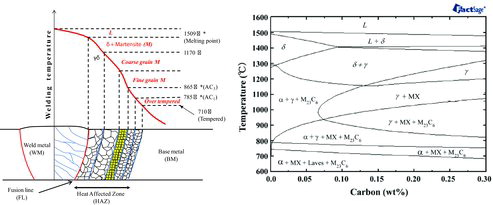
It is expected that ferritic/martensitic (F/M) steels will be used not only as the long-life core material for fast reactors (FRs) but also as blanket materials for fusion reactors due to their excellent void swelling resistance. 11Cr-F/M steel (PNC-FMS) has been developed at the Japan Atomic Energy Agency as wrapper material for the demonstration FR, the Japan Sodium-cooled FR (JSFR) [Citation1–3]. Use of PNC-FMS for FR wrapper tubes requires dissimilar butt welded joints for the Type 316 austenitic stainless steel (SUS316) handling head and the entrance nozzle and PNC-FMS wrapper to ensure safety in the event of an earthquake during FR operation as well as during the handling of irradiated fuel assemblies. F/M steels are generally regarded as being more difficult to employ than austenitic steels are because it is essential to perform postweld heat treatment (PWHT) to temper the brittle martensitic structures formed in the weld metal (WM) and heat affected zones (HAZs). shows a schematic of the structural regions of the welded PNC-FMS joint HAZ as well as a PNC-FMS equilibrium phase diagram, which was calculated by the FactSage thermochemical software and FSstel database [Citation4]. It is well known that phase transformation, coarse grain and fine grain occur in the HAZ due to the welding heat input, as shown in , and that failures typically occur not in base materials (BMs) but in welded joints that include HAZ. Recently, in fossil-fired power plants, the primary concern regarding 9%–12% Cr F/M steels has been that welded joints have significantly lower creep strength than BMs due to fine grain in HAZ, a phenomenon known as Type-IV failure [Citation5–9]. However, Type-IV failure is not an important issue for wrapper tubes in the JSFR because major load on welded joints has sufficiently low internal pressure due to sodium coolant that is under 0.5 MPa. The main issue for PNC-FMS joints is the formation of delta (δ) ferrite along fusion lines (FLs) because δ-ferrite can have detrimental effects on Charpy impact properties during irradiation and thermal aging; namely, increased ductile brittle transition temperature (DBTT) and decreased upper shelf energy (USE)[Citation10–13]. To prevent the formation of δ-ferrite, Narita et al. suggested complete elimination of δ-ferrite by normalization in the first step of PWHT in the manufacture of complex wrapper tubes [Citation14].
Figure 1. Schematic illustration of the structural regions of welded PNC-FMS joint heat affected zone and equilibrium phase diagram of PNC-FMS.
On the other hand, electron beam (EB) welding has also been studied as the primary candidate technology because HAZ in EB welding are narrower than those of other fusion welding processes. However, the fusion welding method is not suitable due to the formation of δ-ferrite. Therefore, chemical compositions should be optimized by increasing austenite formers and decreasing ferrite formers. The objective of this study was to evaluate mechanical properties and microstructures in order to optimize welding conditions and PWHT for the wrapper tube materials on the butt joint between PNC-FMS and SUS316 using EB welding. In addition, the formation behavior of δ-ferrite on different EB welding conditions and with/without nickel-base alloy filler (Inconel 625: 0.02% C, 0.08% Mn, 3.87% Fe, 0.08% Si, 21.53% Cr, 8.94% Mo, 3.51% Nb, 0.13% Co, 0.007% P, Ni-balance) was also evaluated.
2. Experimental procedures
2.1. Materials
Materials used were PNC-FMS and SUS316 plates with a thickness of 5 mm to correspond to the target thickness of the JSFR wrapper tube. The development of PNC-FMS has been reported in detail elsewhere [Citation15]. PNC-FMS plates were produced by the thermo-mechanical process equivalent to the wrapper tube fabrication process, and SUS316 plates were standard products of JIS (Japanese Industrial Standard) G4304 grade. The chemical composition and heat treatment conditions of these materials are shown in .
Table 1. Chemical composition (wt%) of PNC-FMS and SUS316 used in electron beam welding tests.
2.2. EB welding and PWHT
All plates were degaussed by electromagnet before EB welding. Optimization tests for EB welding conditions were performed at a constant acceleration voltage of 70 kV at different parameters; namely, beam currents, focus positions and welding speeds. Type-410 (SUS410) and Type-304 stainless steel (SUS304) rather than PNC-FMS and SUS316 plates were used for these optimization tests in order to investigate weld defects on the specimen surfaces because SUS410 is martensitic steel similar to PNC-FMS and SUS304 is the austenitic steel similar to SUS316. In addition, a 1.2 mm thick Inconel 625 plate was used as a filler material in order to evaluate the formation behavior of δ-ferrite with/without nickel-base alloy filler. This EB test was carried out at an acceleration voltage of 60 kV and a beam current of 47 mA. The welding speed was 400 mm/min and the EB was focused at +40 mm from the surface of butt joint.
After optimization tests, EB dissimilar butt welding between PNC-FMS and SUS316 was carried out. Then, external and metallographic observations and radiographic examination according to JIS Z3104 were carried out to investigate welding defects.
Optimization tests for PWHT were performed at 650 °C for 30 min, 670 °C for 30 min, 690 °C for 15 min, 690 °C for 30 min, 690 °C for 60 min, 710 °C for 30 min and 730 °C for 30 min. The above PWHT conditions were chosen on the basis of PNC-FMS tempering conditions; namely 710 °C for 40 min. Before and after PWHT, Vickers hardness test was performed on a cross-sectional perpendicular to the welding direction with a load of 200 gf for 10 s at regular intervals of 0.25 mm.
2.3. Mechanical and microstructural tests
Transverse and BM tensile tests, whose specimen forms are respectively shown in (a) and (b), were carried out in air using a screw-driven tensile testing machine at an initial strain rate of 5.0 × 10⁻⁵ s−1, which was changed to 1.3 × 10⁻⁵ s−1 after yielding in accordance with JIS G0567. Transverse test specimens were machined to 5 mm thickness to determine the tensile strength of the joint with the original thickness. Test temperature range was between room temperature and 800 °C, and all elongations were determined from the engineering stress–strain curve. Broken specimens were observed by optical microscopy to identify failure locations. It is most important for welds to be overmatched at all test temperatures in order to design fuel subassembly wrapper tubes.
Figure 2. Dimensions of transverse (a) and BM (b) tensile specimens forms.
The Charpy impact specimens were machined to 2.5 × 10.0 × 55.0 mm with a V-notch depth of 2.0 mm, root radius of 0.25 mm and angle of 45 degrees. The V-notch was made on the specimen surface parallel to the direction of plate thickness at the center of WM, FL, HAZ and PNC-FMS, as shown in . Before fabricating V-notches on specimens, all specimens except for PNC-FMS were chemically etched to confirm the location of each position. Charpy impact tests were conducted at temperatures between −150 and 100 °C using a Charpy pendulum impact testing machine.
Figure 3. Metallographic observation of Charpy V-notch center positions: (a) weld metal (WM), (b) fusion line (FL), (c) heat affected zone (HAZ) and (d) top view illustration of welded specimens.
The longitudinal face and root bend test specimens for dissimilar butt weld were machined to 20 × 150 × 5.0 mm, as shown in . The roller bend tests were carried out at room temperature with a bearing radius of 25 mm, a bearing span of 33 mm and a pressing radius of 10 mm in accordance with JIS Z3122 and Z2248. After bend tests, penetration tests were performed to detect cracks and defects.
Figure 4. Dimensions of longitudinal face and root bend specimen for dissimilar butt weld.
Macro-line and micro-line analyses were carried out by electron probe microanalyzer (EPMA) with a probe diameter of 10 and 1 μm at regular intervals of 10 and 1 μm, respectively, in order to investigate compositional change behavior due to EB welding.
3. Results
3.1. Optimization for EB welding conditions
The EB welding condition and appearance on surface are summarized in , and typical appearances after EB welding are shown in . The first EB conditions from No. 1 to 6 were at focus positions near the surface in order to narrow EB diameter on the specimens and the second conditions from No. 7 to 13 were at focus positions over the surface in order to widen penetration beads. The remaining conditions from No. 14 to 17 were increase of both welding speeds and beam currents at focus positions over the surface in order to prevent the shortage in the penetration of BMs.
Table 2. Results of EB welding tests.
Figure 5. External observation of EB welded SUS316/SUS416 specimens: (a) No. 4, (b) No. 13 and (c) No. 17 shown in .
In EB conditions from No. 1 to 6, penetration beads were very narrow but unstable. There were many spatters and humping beads, as shown in (a). In EB conditions from No. 7 to 13, penetration beads were not improved and were unstable. Spatters and humping beads were much larger than those under the former conditions, as shown in (b). On the other hand, in EB conditions from No. 14 to 17, there were no spatters or solidification cracking on specimen surfaces, as shown in (c). This suggested that a reduced density of welding heat-input was caused by accelerating welding speeds, and that the weld formation mechanism was influenced not by keyhole type alone but also by heat flow type.
In the case of dissimilar EB-welded PNC-FMS/SUS316 under the No. 15 condition, (a)–(c) shows respective external observations, X-ray radiography and cross-sectional optical microstructure. There were no surface defects such as cracks, undercut, spatter and so on, or internal defects such as blowhole and lack of fusion ((a) and (b)). Then, as shown in (c), no δ-ferrite was observed adjacent to FL. On the basis of these results, EB welding with conditions from No. 15 to 17 successfully produced defect-free welds on PNC-FMS/SUS316 plates without the formation of δ-ferrite.
Figure 6. EB welded PNC-FMS/SUS316 specimens: (a) external observation, (b) X-ray radiography and (c) cross-sectional optical microstructure.
3.2. Optimization for PWHT conditions
Vickers hardness values before and after PWHT in the WM, FL, HAZ are shown in as a function of Larson Miller Parameter (LMP, constant value: 20), which are visually expressed at temperatures (K) and times (h). The FL and HAZ were determined to be nearest in PNC-FMS HAZ and to be 0.25 mm from this FL, respectively. These values mean representative points for PNC-FMS HAZ.
Figure 7. Relationship between Vickers hardness and LMP: (a) weld metal, (b) fusion line and (c) FL + 0.25 mm (heat affected zone).
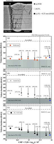
There was significant reduction in hardness at all positions after PWHT compared with the as-welded, as shown in (a)–(c). Hardness values over 19.26 of LMP/1000 (690 °C × 60 min) were nearly equal to those of normalizing and tempering treatments. Furthermore, PWHT conducted for an extended period in the neighborhood of an as-received tempered temperature of 710 °C would suggest that recovery of martensitic structure of PNC-FMS BM near the HAZ was progressing rapidly and that a reduction in strength had occurred due to hardness softening. Therefore, 690 °C for 60 min was selected as the optimum PWHT and the Vickers hardness profiles after this selected PWHT in also showed uniform hardness distribution in WM. After this PWHT, all mechanical and microstructural tests were carried out.
Figure 8. Vickers hardness profiles of EB welded PNC-FMS/SUS316 before and after PWHT (690 °C × 60 min).
3.3. Mechanical properties for dissimilar welds
The transverse tensile properties of the welds as a function of test temperatures are shown in (a) and (b). (c) and (d) shows the optical cross-sectional microstructures of fractured tensile samples at 650 and 700 °C, respectively. The ultimate tensile strength (UTS) of PNC-FMS and SUS316 decreased with an increased test temperature and then these values reversed over about 700 °C which the UTS of SUS316 was higher than that of PNC-FMS, as shown in (a). There was no significant degradation in the UTS of the welds at any test temperature in comparison with both BMs. Total elongations were much less than that of SUS316 BM due to the localized deformation of the BM region in the gauge part as shown in (b). EB welds fractured in SUS316 BM below 650 °C and in PNC-FMS BM over 700 °C, as seen in (c) and (d). These results apparently showed why the localized deformation shifted from SUS316 BM to PNC-FMS BM in the gauge length over 700 °C, which was also corresponding to the change in UTS behavior.
Figure 9. Transverse tensile properties of EB welded PNC-FMS/SUS316: (a) ultimate tensile strength, (b) total elongation, (c) cross section of the fractured tensile sample at 650 °C and (d) cross section of the fractured tensile sample at 700 °C
shows the absorbed energy as a function of test temperatures for WM, FL, HAZ, PNC-FMS BM and SUS316 BM, whose Charpy V-notch positions are shown in . SUS316 Charpy impact tests were only carried out at 25 and 100 °C because low temperature brittleness did not occur for SUS316 BM due to the face centered cubic (FCC) structure. As shown in , in the region of USE and LSE, those of the welds at all positions were much higher than that of BM and cracks initiated in the welds deviated into PNC-FMS BM that was softer than that of welds. Although hardness of SUS316 BM was much softer than those of welds and PNC-FMS BM, cracks did not deviate into SUS316 BM due to FCC structure. From a viewpoint of engineered approach, these results suggested that crack propagation did not occur along the PNC-FMS welded interface and that the welds prevented brittle fractures from taking place if cracks occurred in the region of welds during use. However, it is also important to evaluate fracture toughness of the welds. In the future, we will consider an approach for evaluation of fracture toughness to prevent fracture path deviation. The improved methods are, for example, miniature Charpy impact test, compact tension test with side-groove, side-notched Charpy test [Citation15], and so on.
Figure 10. Charpy impact properties of EB welded PNC-FMS/SUS316: (a) Charpy impact transition curves and specimen appearance with V-notch of (b) weld metal, (c) fusion line and (d) heat affected zone.
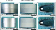
shows the appearance of the longitudinal face and root bend test specimens before and after penetration test. There were no cracks or defects on the bend specimens. This result suggested that welds had appropriate ductility in common with BM.
Figure 11. Appearance of specimens after bend tests: (a) the longitudinal face bend specimen for dissimilar butt weld and (b) the longitudinal root bend specimen for dissimilar butt weld.
3.4. Microstructural observation for dissimilar welds
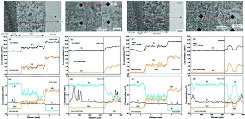
shows the results of EPMA before and after PWHT for this dissimilar weld. As shown (a) and (c), the tendency of chemical compositions in the WM region was a dilution ratio of approximately 50% between PNC-FMS and SUS316. However, there was great variability among positions of WM. In particular, the region where Cr, Ni, and Mo concentrations were high showed a relatively low tendency toward W concentration. These results suggested that the percentage of SUS316 was higher than that of PNC-FMS in the regions because Cr, Ni and Mo concentrations of SUS316 was much higher than that of PNC-FMS and SUS316 contained no W element, as shown in . It was well known that region of WM generally forms dendrite structures through the melting and agitation of dissimilar compositions due to welding heat input by conventional fusion welding. The streak structures in the WM region, which were observed by optical microscopy, as shown in (a), corresponded to this EPMA tendency and also to the flow patterns of the molten weld pool. This EB welding speed was much higher than that of conventional welding and homogeneous dilution of dissimilar compositions in the WM did not occur. As a result, these residual elements of SUS316 were observed along flow morphology during weld solidification. Furthermore, carbon concentration near the FL in the as-welded was maintained at a constant level; however, concentration after PWHT fluctuated locally, as shown in (b) and (d). This result indicated that formation of carbide precipitates was enhanced near the FL region by PWHT. In addition, no segregation of Cr, depletion of carbon or formation of δ-ferrite was observed near the FL region by EPMA. It was suggested that interstitial carbon did not diffuse from PNC-FMS to WM during EB welding because of increase in the welding speed, which means increase in the cooling rate.
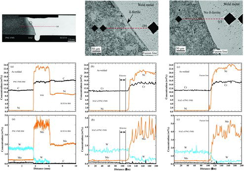
Figure 12. Chemical compositional profile of EB welded PNC-FMS/SUS316 specimens before (a and b) and after (c and d) PWHT.
shows optical microstructure and EPMA analysis for as-dissimilar welded with the Inconel 625 filler. Both formation and no formation of δ-ferrite were observed near the FL region and the dendrite structure was also observed in the WM region. When Inconel 625 filler was used, EB welding diameter had to be broad and speed had to be slow because Ni filler had to be melted fully by welding heat input. Therefore, homogeneous dilution of dissimilar compositions occurred and dendrite structure was observed in the WM region. As compared to (b) and (c), there was no significant diffusion of elements such as Cr, Ni, Mo and W near the FL region with and without δ-ferrite; however, significant decrease in carbon was only seen near the FL region with δ-ferrite. These EPMA results clarified that the formation of δ-ferrite was most affected during EB welding in relation to the carbon migration in the austenite formers, such as Ni and carbon, and the ferrite formers, such as Cr, Mo and W.
Figure 13. Chemical compositional profile of EB welded PNC-FMS/Inconel 625/SUS316 specimens: (a) macro-line scan, (b) micro-line scan in δ-ferrite and (c) micro-line scan in no δ-ferrite.
4. Discussions
As shown in the previous section, different δ-ferrite formation behavior was observed near the FL region with and without nickel-base alloy filler after EB welding.
When PNC-FMS was welded by fusion welding, microstructures of PNC-FMS were two phases of “austenite (γ) + ferrite (δ)” over ferrite-to-austenite transformation temperature of 1170 °C estimated by phase diagram, as shown in . During welding, the δ-ferrite could not include all of the carbon and the interstitial carbon diffused PNC-FMS HAZ to the nickel-base alloy side, which means WM region, because the temperature in the WM region was higher than that in the HAZ region. However, the solid solubility of the nickel-base alloy for carbon was very low and consequently the carbon migration would be inhibited to act as a diffusion barrier. As a result, the WM region was not able to include all carbon and a part of carbon was included in the grain of PNC-FMS near the FL region. Therefore, it was suggested that grains near the FL were not uniformly transformed from martensite into ferrite and that a portion of the grain maintained martensite.
To investigate the effects of δ-ferrite formation on heat input during welding, optical microscopy observations were performed for dissimilar welded PNC-FMS and SUS316 whose welding speed of 500 mm/min was much lower than that of the optimum EB welding condition, as shown in . The formation of δ-ferrite was observed near the FL, and dendrite structure in the WM region was also observed. This suggested that interstitial carbon diffused from PNC-FMS to SUS316 during EB welding because of deterioration of the welding speed and the formation of a band of δ-ferrite near the adjacent FL. This tendency was different from that with increased welding speed using the same materials although this tendency was similar to that of the dissimilar welded material with the Inconel 625 filler as shown in . It has thus been clarified that the formation of δ-ferrite was suppressed not by change of PNC-FMS chemical compositions that decrease in Cr equivalent, but by increase in welding speed that made a contribution to heat flow type in addition to keyhole type.
Figure 14. Cross-sectional optical microstructure of the EB welded PNC-FMS/SUS316 specimen at welding speed of 500 mm/min.
5. Conclusion
In order to investigate the applicability of EB welding to dissimilar butt joint between PNC-FMS and SUS316, various EB welding conditions and PWHT were studied. After optimum EB welding and PWHT, mechanical tests and microstructure were conducted on dissimilar joints. The results are summarized as follows:
For the wrapper tube materials, optimum EB welding conditions were a focus position of 30–40 mm and welding speed of 1750–2000 mm/min and optimum PWHT was performed after welding at 690 °C for 60 min. EB welding successfully produced defect-free dissimilar butt joint between PNC-FMS and SUS316 without nickel-base alloy filler, and there was no formation of δ-ferrite adjacent to the fusion line.
There was no significant degradation in mechanical properties such as tensile, Charpy impact and bend properties, and all dissimilar welds were overmatched.
These EPMA results clarified that the formation of δ-ferrite was most affected during EB welding in relation to the carbon migration.
It was clarified that the formation of δ-ferrite was suppressed by an increase in welding speed, which contributed to heat flow type in addition to keyhole type.
Acknowledgements
The authors would like to thank Dr M. Ono of JFE Techno-Research Corporation for EB welding tests and valuable discussions throughout this investigation.
References
- Nomura S, Shikakura S, Ukai S, Seshimo I, Harada M, Shibahara I, Katsuragawa M. Development of long life FBR core materials. Proc. Int. Conf. on Fast Reactors and Related Fuel Cycles (FR'91); Oct 28–Nov 1, 1991, Kyoto (Japan). p. 7.4.1–7.4.10.
- Shikakura S, Nomura S, Ukai S, Seshimo I, Kano Y, Kuwajima Y, Ito T, Tutakai K, Fujita T. Development of high-strength ferritic/martensitic steel for FBR core materials. J At Energy Soc Japan. 1991;33:1157–1170. Japanese.
- Yano Y, Oka K, Akasaka N, Yoshitake T, Abe Y, Ohnuki S. Effects of microstructural evolution on Charpy impact properties of modified ferritic/martensitic steel after neutron irradiation. J Nucl Sci Technol. 2006;43:648–654.
- Bale CW, Bélisle E, Chartrand P, Decterov SA, Eriksson G, Hack K, Jung I-H, Kang Y-B, Melançon J, Pelton AD, Robelin C, Petersen S. FactSage thermochemical software and database – recent developments. Calphad. 2009;33(2):295–311.
- Laha K, Chandravathi KS, Parameswaran P, Bhanu Sankara Rao K, Mannan SL. Characterization of microstructures across the heat-affected zone of the modified 9Cr-1Mo weld joint to understand its role in promoting Type IV cracking. Metallurgical and Mater Trans A. 2007;38A:58–68.
- Yamada S, Yaguchi M, Ogata T. Microstructural change of a 9Cr steel longitudinal welded tube under internal pressure creep lading. Mater Sci Eng A. 2013;560:450–457.
- Parker J. Factors affecting Type IV creep damage in Grade 91 steel welds. Mater Sci Eng A. 2013;578:430–437.
- Wang X, Xu Q, Liu H, Liu H, Shang W, Ren Y, Yu S. The method for reproducing fine grained HAZ of W strengthened high Cr steel. Mater Sci Eng A. 2014;589:50–56.
- Sakthivel T, Vasudevan M, Laha K, Parameswaran P, Chandravathi KS, Selvi SP, Maduraimuthu V, Mathew MD. Creep rupture behavior of 9Cr-1.8W-0.5Mo-VNb (ASME grade 92) ferritic steel weld join. Mater Sci Eng A. 2014;591:111–120.
- Klueh RL, Alexander DJ. Embrittlement of Cr-Mo steels after low fluence irradiation in HFIR. J Nucl Mater. 1995;218:151–160.
- Klueh RL, Alexander DJ. In: Stoller RE, Kumar AS, and Gelles DS, editors. Irradiation effects on impact behavior of 12Cr-1MoVW and 2-1/4Cr-1Mo Steels. Effects of Radiation on Materials: 15th International Symposium, ASTM STP 1125; Philadelphia (PA): American Society for Testing and Materials; 1992. p. 1256–1266.
- Seran JL, Levy V, Dubuisson P, Gilbon D, Maillard A, Fissolo A, Touron H, Cauvin R, Chalony A, In: Stoller RE, Kumar AS, and Gelles DS, editors. Le Boulbin E. Behavior under neutron of the 15-15Ti and EM10 steels used as standard materials of the Phenix fuel subassembly. 15th International Symposium, ASTM STP 1125; Philadelphia (PA): American Society for Testing and Materials; 1992. p. 1209–1233.
- Klueh RL, Shiba K, Sokolov MA. Embrittlement of irradiated ferritic/martensitic steels in the absence of irradiation hardening. J Nucl Mater. 2008;377:427–437.
- Narita T, Ukai S, Kaito T, Ohtsuka S, Fujiwara M. Development of manufacturing process of PNC-FMS wrapper tube with SUS316 short joint. J Nucl Sci Technol. 2005;42:825–832.
- Hagiwara Y, Tsukamoto S, Otani T, Arakane G, Matsuda K. Toughness evaluation by means of side-notched Charpy test. Tesu-to-Hagane. 2004;90(7):76–82. Japanese.