
 ?Mathematical formulae have been encoded as MathML and are displayed in this HTML version using MathJax in order to improve their display. Uncheck the box to turn MathJax off. This feature requires Javascript. Click on a formula to zoom.
Abstract
Effects of γ-ray irradiation upon crevice corrosion (CC) of type 316L stainless steel (316L SS) as an initiation site of stress corrosion cracking in a boiling water reactor environment have been studied using a material corrosion test loop which could be irradiated with a 60Co γ-ray source during testing. The CC tests were conducted using crevice specimens with various sizes of crevice gaps. Many of the examined specimen surfaces exhibited a selective grain boundary dissolution; that is, intergranular attack (IGA) as a result of the CC when the crevice gap size was lower than a certain value. The IGA initiation time was shortened by the γ-ray irradiation. The IGA occurred mostly near the crevice mouth at a distance of less than 2 mm from the mouth edge. When γ-ray exposure had occurred, it was found that the number of IGA sites deeper in the crevice increased compared with the IGA site distribution under the no-irradiation condition. Since the electrochemical corrosion potential inside crevice specimens must be low under the conditions for which IGA could occur, it was assumed that γ-ray irradiation accelerated the corrosion rate of 316L SS by decreasing the Fe2+ surface activity inside the crevice or increasing the cathodic current of radiolytic oxidants on the crevice surface. It was concluded that γ-ray irradiation affects the IGA occurrence not only temporally but also spatially.
1. Introduction
The intergranular stress corrosion cracking (IGSCC) of structural materials, such as type 304 stainless steel (304 SS) and type 316L stainless steel (316L SS), has an impact on safety, reliability, and economic efficiency of light water reactor (LWR) plants. Many research efforts have been directed toward understanding its mechanism and many countermeasures have been identified and taken to mitigate the IGSCC conditions. It is well known that IGSCC in 304 and 316L SSs occurs when effects overlap, including degradation of corrosion resistance of materials, generation of residual stress at welds, and presence of a corrosive environment (high oxidant concentration, high electrochemical corrosion potential (ECP), and high caustic anion concentration).
Both γ-ray and neutron irradiations also affect the IGSCC and irradiation-assisted stress corrosion cracking of the materials used in LWRs in the following ways. (1) These irradiations change material micro-structures, hardness, corrosion resistivity, and other properties [Citation1]. (2) They cause stress redistribution. (3) They make the reactor water corrosive by causing water radiolysis in which radiolytic species such as hydrogen peroxide (H2O2) are generated, and this raises the ECP of the materials enough to cause IGSCC during plant operation [Citation2].
Among studies about irradiation effects on IGSCC, the formation process of the corrosive environment and effects on the oxides on and in the reactor materials are important issues for water chemistry control. This is because irradiation effects are closely related to the effectiveness of IGSCC mitigation countermeasures such as hydrogen water chemistry [Citation3] and noble metal chemical addition [Citation4].
In addition, many internal components in a reactor have design crevices and non-design crevices such as cracks and spaces between base metal and peeling oxide films. As shown in , like for IGSCC, crevice corrosion (CC) occurs when effects overlap, including the corrosive environment, material properties, and crevice shape. It is considered that CC is caused by the different oxidant conditions inside and outside a crevice.
Figure 1. Relationships among CC parameters in a nuclear power plant.
Under the crevice condition, the IGSCC mean failure time in the constant load test has been reported to be shorter than that without any crevice [Citation5]. Therefore, there is still room for further study on the CC behavior in high-temperature water under irradiation, especially as an IGSCC initiation site.
The authors have previously conducted CC tests of 304 SS and 316L SS in high-temperature water under γ-irradiation to understand the governing parameters for the formation of a corrosive environment inside the crevice during irradiation. Intergranular attack (IGA) was found to result from CC. The CC occurred when the crevice size was less than a certain value in which the ECP inside the crevice became much lower than the value outside [Citation6]. Also, irradiation was found to accelerate IGA initiation since the presence of radiolytic products made the crevice water chemistry condition severer. Moreover, since the crevice water is affected by pH, metal ion concentration, and oxidant concentration, it was thought reasonable to evaluate the environment in a crevice by measuring the ECP there.
Therefore, objectives of this study were to understand radiation effects, especially γ-ray irradiation effects, on the CC of SSs used under BWR (Boiling Water Reactor) operating conditions from the viewpoint of local cell formation. The CC tests were conducted with a material test loop that allowed the use of a 60Co γ-ray source. The test specimen surfaces were examined with a scanning electron microscope (SEM). The distribution of the IGA initiation sites caused by the CC was examined using the SEM images.
2. Experimental
The experimental procedure and the setup were the same as used previously [Citation6]. The CC tests of both 304 and 316L SSs were conducted at 288 °C under 60Co γ-ray irradiation at a relatively high conductivity that was controlled by sulfuric acid addition (0.1 ppm) at 8 ppm dissolved oxygen (DO) concentration. Sulfate ion was selected for study as it is the major corrosive impurity in BWR coolant. The high-temperature and high-pressure water loop, designed for carrying out material tests under γ-ray irradiation conditions, was used (). The autoclave of the loop was made of 316L SS. The γ-ray absorbed dose rate in the autoclave was 104 Gy/h at the specimen location. The water flow rate from the makeup tank was kept at 10 L/h by using the feed pump. Pressure of the loop was set to 8 MPa with a pressure regulator so as not to cause water boiling. The water was heated to 288 °C using the heaters surrounding the autoclave then maintained the temperature. The water conductivity in the makeup water tank was kept below 6 μS/m by passing the water through an ion exchange resin column. DO concentration in the makeup water tank was controlled by bubbling O2 and Ar gases into the tank. Organic carbon in the water was removed by decomposing it with ultraviolet light. DO concentration and conductivity of the water were continuously measured using in-line monitors. After the water had passed through the autoclave, it was deionized using the ion exchange resin and sent back into the makeup tank. Test conditions are listed in .
Table 1. CC test conditions.
Figure 2. Experimental setup for CC tests under the γ-ray irradiation conditions.
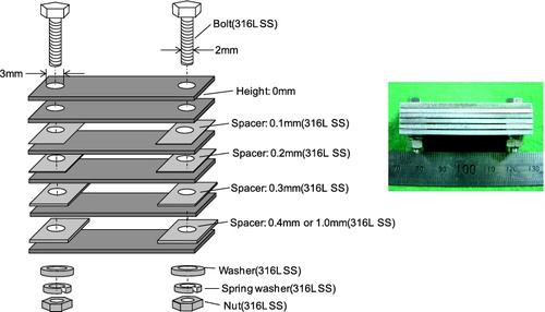
The CC test specimens were made of 304 SS and 316L SS which were subjected to solution annealing and sensitizing heat treatment. Their chemical compositions are listed in . A photo and schematic drawing of the CC specimens are shown in . The crevice gap between each specimen was adjusted by inserting spacers at both ends of a specimen. Hematite (Fe2O3) was filled between the CC specimens to examine the effects of the corrosion product deposition inside the crevice.
Table 2. Chemical compositions of SSs for CC tests and internal ECP measurements.
Figure 3. Specimens used in CC tests.
The corrosion state of the CC specimen surfaces was examined with the SEM (Hitachi S-3000FB). Whether or not there was any CC occurrence and if so, where the CC was initiated was determined from the SEM images. When the Fe2O3 filling was strongly fixed to the surfaces of the specimens, they were cleaned by ultrasonic cleaning and rinsed with permanganic acid and oxalic acid.
Surface oxide films formed on the crevice surfaces under both γ-ray irradiation and no-irradiation conditions were observed with a laser Raman spectroscope (Renishaw®, RAMASCOPE system 3000) after ultrasonic cleaning, without rinsing.
3. Results and discussion
3.1. Crevice corrosion tests
Previously, IGA was found to be a characteristic type of damage from SEM surface observation results for the CC test of a 316L SS specimen [Citation6]. The IGA was examined as an index of the CC of 304 and 316L SSs in the simulated BWR environment. The IGA was found either under the irradiation condition or the no-irradiation condition. There was no difference in the form of the IGA itself between these conditions. In the IGA region, dissolution of grain boundaries of 316L SS was clearly observed and some grains dropping out of the specimen surfaces were found as shown in . However, during γ irradiation, the IGA occurred in a shorter test period than for the no-irradiation condition in addition to the strong fixation of the Fe2O3 filling on the crevice surface.
Based on the test results obtained in the previous study [Citation6], the relationship of the IGA occurrence to various CC test parameters was summarized as shown in . Even though the specimens were immersed in high-temperature water for 1500 h, if they had not been exposed to γ-ray irradiation and there was no Fe2O3 filling, the specimen surfaces after the CC tests did not have much damage and metallic shine was observed after cleaning with oxalic acid. If the Fe2O3 filling was present, the IGA occurred at 1500 h. Then, the Fe2O3 filling was strongly fixed to the surfaces of the specimens and a small portion of it was not removed by ultrasonic cleaning. In this case, two acid cleanings could remove the adhered Fe2O3 filling from the specimens. Moreover the γ-ray irradiation accelerated the IGA initiation and caused strong fixation of the Fe2O3 filling on the surfaces. The ultrasonic cleaning could not remove the surface oxide significantly. Even the two acid cleanings could not restore the metallic shine of the specimen surfaces.
Figure 4. SEM images of a 316L SS specimen (with γ-ray irradiation for 500 h and Fe2O3 filling; crevice gap, 0.2 mm) [Citation6].
![Figure 4. SEM images of a 316L SS specimen (with γ-ray irradiation for 500 h and Fe2O3 filling; crevice gap, 0.2 mm) [Citation6].](/cms/asset/e4140575-9409-45f4-96b7-06d26219c27f/tnst_a_971899_f0004_b.gif)
Figure 5. Relationships between IGA occurrence and various CC test parameters [Citation6].
![Figure 5. Relationships between IGA occurrence and various CC test parameters [Citation6].](/cms/asset/37d8bba6-7cf4-4865-81c6-b10848c11e63/tnst_a_971899_f0005_b.gif)
3.2. IGA occurrence site distributions
In this work, the distribution of the IGA initiation site on the crevice surfaces was examined to understand the local cell which causes the motive force of the CC. The crevice surfaces of the crevice-corroded 316LSS specimens were examined after the ultrasonic cleaning and the two acid cleanings to see the IGA occurrence below the deposited oxide. SEM was used to look for the IGA sites. Images showing observed IGA occurrence distribution on the crevice surface are shown in for both no-irradiation and γ-irradiation conditions.
Figure 6. Observed IGA occurrence distribution on the crevice surfaces.
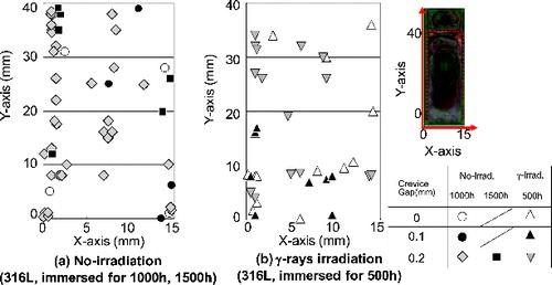
In the case of the no-irradiation condition (316L SS specimens were immersed for 1000 or 1500 h), the IGA was observed mainly near the edge of the specimens, that is a few millimeter from the crevice mouth. On the other hand, under the γ-irradiation condition, it seemed that the number of IGA sites near the center of the specimens increased for the 316L CC test specimens immersed for 500 h. Under the γ-irradiation condition, although immersion time was shorter compared with the no-irradiation condition, the considerable numbers of IGA sites had formed.
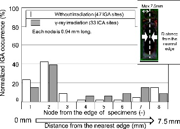
The relationship between the distance from the crevice mouth, which is the nearest edge of the specimens, and the normalized IGA occurrence is plotted in . Distance from the crevice mouth was divided into eight nodes, each 0.94 mm long. The IGA site numbers of each node were counted. Total numbers of IGA sites were 47 and 33 for no-irradiation and γ-irradiation conditions, respectively. The IGA site number of each node was then normalized by the total IGA site number. In the case of the no-irradiation condition, almost 65% of the IGA sites were near the edge of the specimens. Under the γ-ray irradiation, about 55% of the IGA sites were found at less than 1.9 mm distance from the crevice mouth and in addition, the IGA occurrence in the region from 3.8 to 6.6 mm (from fourth to seventh nodes) was more than under the no-irradiation condition. Therefore, the γ-ray irradiation could enhance the IGA initiation deep in the crevice even though motive force of the local cell formed by the bulk oxidants was weaker at the center of the crevice.
Figure 7. Relationship between distance from nearest edge of specimens and normalized IGA occurrence.
3.3. IGA occurrence and ECP distribution inside the crevice
Although many parameters have been thought to be related to IGA occurrence, electrochemical reactions are the most important. In the authors’ previous study [Citation6], the ECP measurement inside the crevice under the no-irradiation condition was conducted as described below. An external-type Ag/AgCl reference electrode and a zirconia (Zr) wire-type reference electrode for the internal ECP were set in the autoclave to measure ECPs of the 316L SS crevice specimens. In the measurements, a crevice was formed with a polytetrafluoroethylene (PTFE) plate, a 316L SS plate, and two spacers. The Zr wire-type reference electrode was inserted into the center of the crevice through the PTFE plate. Potential difference between the Zr and 316L SS was measured with an electrometer (Keithley6512). The internal ECP measured at the center of the CC test specimen without irradiation had crevice gap dependence as shown in . The internal ECP was as high as that in the bulk (the external ECP) when the crevice gap size was above 0.4 mm. The external ECP of SS at 8 ppm DO was within 0–0.2 V vs. SHE (standard hydrogen electrode). The internal ECP decreased with a decrease of the crevice gap size from 0.4 to 0.2 mm, and below 0.2 mm, the internal ECP decreased to values in the range from −0.4 to −0.6 V vs. SHE [Citation7]. This range included the value of the redox potential of water on the SS, and the internal ECP was approximately at the same level as the internal ECP under irradiation; that is, −0.39V (vs. SHE) in 2 ppm DO at 288 °C [Citation8]. Since the external ECP was constant at the given water chemistry conditions, the difference between the internal ECP and the external ECP (ΔECP) became larger as the crevice gap size decreased.
Figure 8. Relationship between the internal ECP and the IGA initiation due to CC under no-irradiation condition [Citation6].
![Figure 8. Relationship between the internal ECP and the IGA initiation due to CC under no-irradiation condition [Citation6].](/cms/asset/1c00a059-78d1-4c3d-b7be-26f2b29087e1/tnst_a_971899_f0008_b.gif)
According to other reported experimental findings in which the ECP distribution inside a crevice was measured in high temperature and high purity water [Citation9], internal ECP at the crevice mouth is almost the same as the external ECP. However, the internal ECP decreased steeply along the crevice depth direction (). When bulk water was stagnant, the ECP inside the crevice leveled off at the lowest potential value at a depth of a few millimeters from the crevice mouth; these steep ECP decreases were caused by oxygen consumption on the crevice surface during diffusion of oxygen along the crevice depth direction [Citation9].
Figure 9. ECP distribution inside a crevice for each bulk water flow condition [Citation10].
![Figure 9. ECP distribution inside a crevice for each bulk water flow condition [Citation10].](/cms/asset/42dd8fbc-eb0c-4cc8-b97a-ad97d1bfaf9b/tnst_a_971899_f0009_b.gif)
Based on the point defect model (PDM) [Citation10], the time of the protective film break t is given as the following equation:
(1)
(1) Here, ξ/Jm is a constant which determines the passive film break time, χ is the equivalent charge, F is the Faraday's constant, α is a coefficient for ionic species, V is the potential, Vc is the critical potential, R is the gas constant, and T is the absolute temperature. Vc is given by
(2)
(2) Here, aimpurity is the activity of anion impurity, u is the barrier layer volume, and
is the diffusion coefficient of the cation vacancy.
This model suggests that the protective film breaks when the cation void flux becomes larger than the critical flux with the increase of V − Vc. As an analogy, V − Vc is rewritten as V − Vin + Vin − Vc, where Vin is the ECP inside the crevice. When ΔE(=V − Vin) which drives the CC increases, sulfate ion concentration increases by the CC to keep the charge balance due to Fe ions dissolution. Then, according to Equation (2), the critical potential Vc for the protective film break is lowered with an increase of sulfate ion concentration inside the crevice. The Vin − Vc becomes larger before CC causes the sulfate ion concentration increase. Then, the occurrence of film break also becomes larger exponentially. Therefore, Equation (1) is rewritten as
(1′)
(1′) where ΔVc = Vin − Vc.
These potential changes are the driving force of the IGA. The deeper inside the crevice a region is, the more sensitive it is to the protective film break. To see the effects of the Vin and Vc, a simple calculation was conducted using Equation (1′). V was the bulk potential and set to be 0.2 V vs. SHE. Vin was set to be 0.2 V vs. SHE at the crevice mouth and to decrease linearly as 0.2 times the relative distance from the crevice mouth, becoming −0.6 V vs. SHE at the crevice tip (1.0 of the relative distance). Initial Vc was 0 V vs. SHE and Vc was set to be the same value as Vin. Calculated t was normalized by the value at the crevice mouth. As shown in , the protective film break time was shortened sharply along with the relative crevice depth because Vin and Vc linearly decreased. After Vin and Vc leveled off, the protective film break time was constant. This calculation ratio of cathode to anode current densities was assumed to be unity. However, in case of the CC, this ratio must be larger than unity, so the relative protective film break time must be shorter in the region where Vin and Vc level off because of the increase in the anodic current density.
Figure 10. Relationship between the protection film break time and potential distribution inside a crevice.
In addition, motive force from the bulk surface does not go an infinite distance, and then the coupling current which flows between the cathodic region and the anodic region also does not go far into the crevice. Therefore, IGA occurrence must have a peak at the location where the ECP inside the crevice Vc starts leveling off. Since a small portion of the coupling current can reach deep inside the crevice, some IGA occurs at deep positions. If ΔE is small, CC sufficient to cause increased sulfate ion concentration does not occur, then Vc does not decrease and ΔVc remains small. Therefore, the decrease of Vin must be an important process in the development of CC.
3.4. Irradiation effects on IGA occurrence
Based on the CC results, the IGA due to the CC could have occurred when the internal ECP was lowered below −0.4 V vs. SHE and ΔECP became large under the test conditions in this study. In this situation, the anodic region must be polarized and dissolved by a large motive force of the ΔECP in the active state [Citation9] with the help of the sulfate ion. Even if the crevice is irradiated, the internal ECP must be low.
As discussed elsewhere [Citation6], the irradiation effect on the CC must be the change of the Fe ion concentration near the surface of the crevice mouth. Of course, if the oxygen or H2O2 concentration in the bulk is low, ECP of the SS outside the crevice also drastically increases due to this irradiation effect. However, in this test condition, the external ECP did not increase much [Citation11] since DO was as high as 8 ppm. Therefore, the difference in corrosion behavior must be attributed to water chemistry inside the crevice, that is oxidation of Fe2+ to Fe3+ by OH (hydroxyl radical), described as the following equation:
(3)
(3)
The activity of Fe2+ on the surface decreases and consequently, the corrosion rate of the base metal becomes faster than that for no-irradiation. The acceleration of dissolution of Fe2+ and oxidation of Fe2+ to Fe3+ by OH or H2O2 would be the reason why Fe2O3 was observed on the crevice specimens that had experienced γ-ray irradiation in this study while the internal ECP must be too low to form Fe2O3 on the crevice surface [Citation6].
The maximum cathodic current density i was calculated by
(4)
(4) Here, ζ is the coefficient for unit conversion. zOH and
are the charge numbers with the cathodic reaction (for ·OH it is 1 and for H2O2 it is 2) [Citation7]. g(·OH) = 4.86 and g(H2O2) = 0.31 are g-values of ·OH and H2O2 for γ-rays [Citation12]. Q is the dose rate at the occluded volume in the crevice. NA is Avogadro's number. H is the crevice gap. Crevice width and depth are set as unity. Since the crevice consists of two surfaces, current density is divided by 2. Also, mobility of oxidants is assumed to be infinity. Only OH and H2O2 of primary radiolytic products were considered. If ·OH was assumed to react rapidly with other chemical species and not to react on the surface, H2O2 would be the main oxidant and the only oxidant in the crevice environment. Although the concentrations of OH and H2O2 in a crevice are needed to evaluate pH [Citation13], thermal decomposition [Citation14], and corrosion reaction in detail, since it was difficult to evaluate these three individually, the ECP in a crevice environment was estimated as in the equilibrium state.
Equation (4) is rewritten as following:
(5)
(5)
At the test condition dose rate Q = 104 Gy/h, the maximum current density of ·OH + H2O2 and H2O2 was calculated as shown in . Maximum current densities for Equations (4) and (5) were proportional to the crevice gap. Anodic current density of the 316L SS in high temperature and high purity water and that with sulfate ion [Citation7] behaved as shown in the figure. Previously [Citation6], anodic current density was discussed based on the polarization curve of the 304 SS. However, that for the 316L SS is more suitable for this study.
Figure 11 Relationship between the maximum current density of radiolytic hydrogen peroxide and the passive current.
IGA was observed at distances below 0.2 mm from the crevice mouth for the CC specimens used in this study. In this case, even if both ·OH and H2O2 were considered to react completely on the crevice surfaces, the maximum current density was estimated as ca. 1.5 × 10⁻⁶ A/cm2. Then, the maximum current density intersected the anodic polarization curve at about 0 V vs. SHE in pure water at most and at −0.56 V vs. SHE in the presence of 1 ppm sulfuric acid. In the CC tests under γ-ray irradiation, sulfuric acid was added to keep conductivity around 100 μS/m and this corresponded to about 0.1 ppm sulfuric acid concentration. Therefore, under γ-ray irradiation at 104 Gy/h, the internal ECP of 316L SS must be in a range from −0.57 to 0 V vs. SHE. If it was assumed that only H2O2 contributed to the determination of the internal ECP, the internal ECP was estimated to be below −0.4 V vs. SHE since the maximum current density by Equation (2) was 1 × 10⁻⁷ A/cm2 at the 0.2 mm crevice gap. Moreover, if corrosion product is present in the crevice, the amount of water in the crevice is less than that without corrosion product. The maximum current density also becomes smaller. Considering the IGA occurrence and the presence of SO42− and corrosion product in the crevice, the internal ECP of 316L SS crevice under irradiation must be low [Citation8].
In addition, γ-ray irradiation affected the distribution of the IGA occurrence. The γ-ray irradiation could cause the IGA at a deep part of the crevice even though motive force of a local cell formed by the bulk oxidants cannot sufficiently reach the center of the crevice as shown in . The ECP inside the crevice must be low as discussed above. However, irradiation supplies oxidants such as O2, H2O2 and ·OH and a cathodic current is generated deep in the crevice. Also, irradiation must accelerate the corrosion rate inside the crevice by changing the Fe2+ ion concentration near the surface of the crevice surface. This must change the critical flux of the PDM. Therefore, as discussed above, the protective film destruction time is shortened in every region of the crevice.
It was assumed that γ-rays accelerated the corrosion rate of 316L SS with decreasing Fe2+ activity inside the crevice or increasing cathodic current of radiolytic oxidants on the crevice surface. The γ-ray irradiation affected the IGA occurrence not only temporally but also spatially. This forms a local cell. Oxidants diffuse into the crevice and are consumed on the cathodic site near the crevice mouth. At the same time, metal dissolves at the anodic site inside the crevice. Impurity anions are increased to a high concentration in the crevice by motive force of the local cell. Then, the water chemistry in the crevice becomes more corrosive and the crevice acts as an acceleration factor for IGSCC when stress is present ().
Figure 12. Schematic of the CC mechanism.
4. Conclusion
Effects of γ-ray irradiation upon CC of 316L SS as an initiation site of IGSCC in a BWR environment have been studied using a material corrosion test loop which allowed irradiation with a 60Co γ-ray source during testing. The findings are summarized as follows.
CC tests of 304 SS and 316L SS were conducted using crevice specimens with various crevice gap sizes in high-temperature water under γ-ray irradiation to understand the CC governing parameters. The IGA occurred as a result of the CC when the crevice gap size was less than a certain value and was accelerated by the simulated corrosion product filling. In the presence of γ-rays, the IGA was observed in a shorter immersion time than for the no-irradiation condition.
Most of the IGA occurred at a distance less than 2 mm from the crevice mouth. When γ-ray exposure had occurred, it was found that the number of IGA sites deep in the crevice increased compared with the IGA site distribution under the no-irradiation condition. This was because the ECP inside the crevice specimens must be low under the conditions in which the IGA could occur.
References
- Was GS, Busby JT. Role of irradiated microstructure and microchemistry in irradiation-assisted stress corrosion cracking. Philos Mag. 2005;85(4–7):443–465.
- Wada Y, Ishida K, Tachibana M. Effectiveness analysis of noble metal treatment to mitigation of intergranular stress corrosion cracking of stainless steel in BWR reactor water environment. Proceedings of 11th International Confererence on Environmental Degradation of Materials in Nuclear Power Systems; 2003 Aug 10−14; Stevenson (WA). ( CD-ROM).
- Law RJ, Indig ME, Lin CC, Cowan RL. Suppression of radiolytic oxygen produced in a BWR by feedwater hydrogen addition. Proceedings of 3rd International Conference on Water Chemistry of Nuclear Reactor Systems; 1983 Oct 17–21; Bournemouth, UK.
- Hettiarachchi S, Law RJ, Diaz TP, Cowan RL, Keith W, Pathania RS. The first in-plant demonstration of noble metal chemical addition technology for IGSCC mitigation of BWR internals. Proceedings of 8th International Symposium on Environmental Degradation of Materials in Nuclear Power Systems – Water Reactors; 1997 Aug 10–14; Amelia Island (FL).
- Ohnaka N, Shoji S, Kikuchi E, Minato A, Ito H. [Effects of environmental factors on the IGSCC susceptibility of sensitized SUS 304 stainless steel in high temperature water]. Boshoku-Gijutsu. 1983;32:214–220. Japanese.
- Wada Y, Watanabe A, Ishida K, Tachibana M, Shigenaka N, Kawashima N, Aizawa M. Local radiolysis and electrochemical corrosion potential in crevice environment. Proceedings of the 9th International Radiolysis, Electrochemistry and Material Performance Workshop; 2012 Sep 28; Paris, France. ( [CD-ROM] ISBN978-2-9516195-3-1).
- Tachibana M, Ishida K, Wada Y, Shimizu R, Ota N, Hara N. Determining factors for anodic polarization curves of typical structural materials of boiling water reactors in high temperature–high purity water. J Nucl Sci Technol. 2007;44:253–262.
- Miller WD, Indig ME, Lawrence Nelson J, Wozadlo GP. Investigation of the protection potential against irradiation assisted stress corrosion cracking. Proceedings of 5th International Symposium on Environmental Degradation of Materials in Nuclear Power Systems –Water Reactors; 1991 Aug 25–29; Monterey (CA).
- Wada Y, Ishida K, Tachibana M, Aizawa M, Fuse M. Hydrazine and hydrogen coinjection to mitigate stress corrosion cracking of structural materials in boiling water reactors (VII) – effects of bulk water chemistry on ECP distribution inside a crack. J Nucl Sci Technol. 2007;44(11):1448–1457.
- Chao CY, Lin LF, MacDonald DD. A point defect model for anodic passive films. J Electrochem Soc. 1981;128(6):1187–1194.
- Wada Y, Ishida K, Watanabe A, Tachibana M, Aizawa M, Fuse M. Effects of γ-rays irradiation upon SCC initiation and propagation under BWR conditions. Proceedings of 14th International Confererenec on Environmental Degradation of Materials in Nuclear Power Systems; 2009 Aug 23–27; Virginia Beach (VA). (CD-ROM).
- Wada Y, Ishida K, Tachibana M, Aizawa M, Fuse M, Kadoi E, Takiguchi H. Hydrazine and hydrogen co-injection to mitigate stress corrosion cracking of structural materials in boiling water reactors (IV). J Nucl Sci Technol. 2007;44(4):607–622.
- Spunks JWT, Woods RJ. An introduction to radiation chemistry. Vol. 262. New York (NY): Wiley; 1990.
- Uchida S, Shigenaka N, Tachibana M, Wada Y, Sakai M, Akamine K, Ohsumi K. Effects of hydrogen peroxide on intergranular stress corrosion cracking of stainless steel in high temperature water (I). J Nucl Sci Technol. 1998;35:301–308.