 ?Mathematical formulae have been encoded as MathML and are displayed in this HTML version using MathJax in order to improve their display. Uncheck the box to turn MathJax off. This feature requires Javascript. Click on a formula to zoom.
Abstract
After the Fukushima accident, several investigation reports, including experiments and simulations have been done for each of the affected units to completely understand the accident progression and use their results to improve the knowledge of severe accident management and the severe codes performance. In Unit 2, the major uncertainties are related with the reactor core isolation cooling (RCIC) system performance during the accident progression especially focused in the RCIC turbine, which is assumed to work in two-phase flow. The main objective of this study is to analyze the RCIC turbine performance under two-phase flow scenarios under the assumption that the power produced by the turbine is lower than expected due to the liquid phase in the flow. A degradation coefficient quantifying the turbine power reduction is developed as a function of the flow quality by using the sonic speed reduction at critical flow conditions principle obtained by applying the non-homogeneous equilibrium model (NHEM). The degradation coefficient was applied to RELAP/ScdapSIM severe accident code showing a drastic reduction of the turbine-generated power during two-phase flow and obtaining a RCIC system behavior closer to the Tokyo electric power company (TEPCO) investigation report conclusions.
1. Introduction
Fukushima accident has been a wakeup call for nuclear safety and all the data recorded during the accident have been analyzed in depth in several investigation reports gathered in the Information Portal for the Fukushima-Daiichi Accident Analysis and Decommissioning Activities [Citation1].
Due to the lack of data caused by the station blackout, severe accident simulation codes, like MELCOR [Citation2], MAAP [Citation3], RELAP/Scdap [Citation4] and SAMPSON [Citation5,Citation6], have become useful tools to completely understand the accident progression in the different units. The objectives of those analyses were to make an accurate prediction of the accident progression as well as improve the codes itself with all the new information learned from it.
Regarding Unit 2, investigation reports [Citation1–6] agreed that the accident progression was majorly conditioned by the RCIC (reactor core isolation cooling) system performance; the RCIC is designed to ensure that sufficient reactor water inventory is maintained in the vessel to permit adequate core cooling by providing a water makeup from either the CST (condensate storage tank) or the suppression pool. This prevents the reactor fuel from overheating in the event that the reactor is isolated from the secondary plant. Usually, an RCIC trips at the reactor water level of L-8 (top active fuel (TAF) + 5.65 m) to prevent steam containing water droplets from flowing into the turbine. However, in case of the Fukushima accident, due to the loss of power and the 70 h operation time recorded by Tokyo electric power company (TEPCO) [Citation1], it is assumed that the stop order never arrived creating a two-phase flow situation in the turbine.
Steam turbines like RCIC one are designed to work under a single-phase steam flow. In case of wet steam (steam + water), the phenomenology is more complicated, thus there are additional effects that should be taken into consideration; for example, the effect of the differing velocities between both phases.
In a normal steam turbine, the blade angles have been designed to fit the steam velocity vector. Water, even assuming a correct inlet angle, due to its properties would easily adhere to the blades, moving outward toward the tips on account of centrifugal force. Since this phenomenon takes place over the entire blade it will lead to a larger moisture concentration being incremented at each successive stage.
Although some water would be trapped by the so-called water catchers, the rest of the water will lose almost all its kinetic energy leading to a reduced energy of the moisture.
Several analysis have been done regarding the RCIC performance during Fukushima Unit 2; TEPCO [Citation1,Citation3] and the Institute of Applied Energy (IAE) [Citation7] stated the incongruence between the simulation results and the onsite measured data.
In their analysis, TEPCO [Citation3] failed to reproduce the reactor pressure vessel (RPV) pressure due to the difficulty in quantitatively evaluating the water injection capability of RCIC in a two-phase flow scenario. Eventually, to fit their results, they assumed that the water injection flow was smaller than the rated flow due to a lower rotational speed and fixed the flow rate of RCIC to 30 m3/h, which is about one-third of the rated flow rate of 95 m3/h.
IAE [Citation7] also assumed degradation in the turbine due to water presence. They used an iteration process based on a numerical analysis of the RCIC system to fit their simulation results to the TEPCO data obtaining a reduction factor for the turbine as a function of the void fraction of the flow.
The objective of this paper is focused on Fukushima Unit 2 analysis uncertainties originated from the RCIC operation under the assumption that the turbine is underperformance due to the presence of water in the flow. A new model is developed with the consideration of two-phase flow degradation in RCIC turbine power. To quantify the moisture energy loss due to water, non-homogeneous equilibrium model (NHEM) will be used, to set up a degradation coefficient (ηNHEM) by calculating the output power using the velocity triangles at critical flow condition and at different upstream flow qualities and comparing them with the single-phase flow. The degradation coefficient has been applied to RELAP/ScdapSIM severe accident code in order to evaluate its effects on the turbine performance and resolve the problems related to RCIC modeling, which affect the Unit 2 accident analysis.
1.1. Methodology
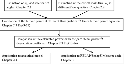
Development of the turbine degradation coefficient based on the NHEM and its application into numerical and computational analysis summarized in the flow chart shown in starts with the estimation of some geometric parameters of the turbine. Those parameters are the nozzle critical area Acr and inlet/outlet angles of the blade. They are estimated using the design values from and the turbine design equations [Citation8].
Table 1. Fukushima Daiichi Unit 2 RCIC design specifications.
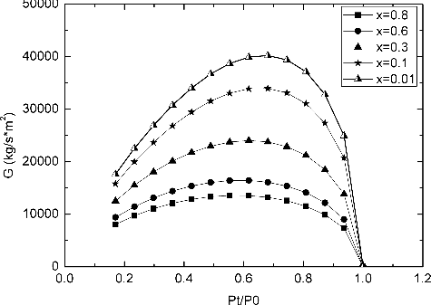
At the same time, the NHEM equations are used to calculate and plot the mass flux values for different turbine upstream qualities depending on the expansion experienced by the fluid. The results are displayed in with the objective to find the critical mass flux Gc for each flow quality.
Then, using the data from previous steps, the critical mass flow for each quality mc, and the velocity triangles for steam and water phases can be found. Applying the Euler turbine work equation, the maximum power that the turbine can achieve for each different upstream flow quality can be obtained.
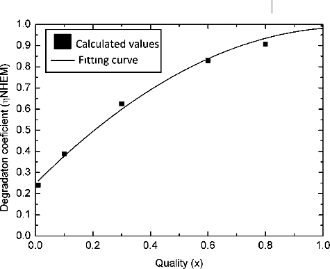
The last step to successfully quantify how the power is reduced as a function of the water fraction in the flow is simply to compare the power of each quality W(x0) with the pure steam (single phase) power Wpure steam and plot the results as shown in
Then, the coefficient is used either for the analytical model or the RELAP/ScdapSIM computational analysis described in Sections 2 and 3.
2. RCIC turbine
2.1. Characterization of Turbine parameters
Prior to use the NHEM, the turbine geometry must be found. The geometry will be used to find the velocity triangles independent of the scenario and, in conjunction with the Euler turbine work equation, to find the turbine output power.
The geometry will be calculated under single-phase scenario using the data from the specification sheet summarized in [Citation7].
shows the design parameters for the RCIC system for Fukushima Unit 3, which has the same specifications as the one in Unit 2.
Before impacting the blade, the flow has to pass through the nozzle where its pressure is reduced while its velocity is augmented keeping the overall energy constant. If the value of 2.51 kg/s of steam from is considered to be the critical flow for single-phase conditions, the critical area of the nozzle is described by EquationEquation (1)
(1)
(1) [Citation8],
(1)
(1) where Acr (m2) is the critical area of the nozzle, pups (Pa) and ρups (kg/m3) are the upstream pressure and density, and n is a parameter equal to 1.135 for saturated steam.
The pressure reduction produced in the nozzle with Acr is described by EquationEquation (2)(2)
(2) [Citation8],
(2)
(2) where pdws (Pa) is the downstream pressure corresponding to the critical expansion and pups is the upstream pressure corresponding to 7.83 MPa from .
Since the energy in the expansion is constant, the velocity is incremented as shown in EquationEquation (3)(3)
(3) [Citation8],
(3)
(3) where hups (kJ/kg) and Vups (m/s) are the enthalpy and velocity upstream the nozzle and hdws (kJ/kg) and Vdws are the enthalpy and velocity downstream the nozzle. Vdws is the downstream velocity (outlet) of the nozzle but also is the inlet velocity of the flow to the blade. Using the velocity triangles in junction with the previous calculated Vdws and the velocity of the blade (Vb) from , the inlet/outlet angles can be calculated.
2.2. Non-homogeneous equilibrium model
The NHEM, originally developed by Moody (1965) [Citation9], is an extension of the HEM (homogeneous equilibrium model), which allows different velocities between vapor and liquid phases. The slip ratio, S, is defined as the ratio between velocities. This ratio is also considered as a variable, which determines the conditions of maximum mass flux. The mass flux can be described by EquationEquation (4)(4)
(4) ,
(4)
(4) where G is the mass flux (kg/s*m2), h0 is the enthalpy at upstream condition (kJ/kg) which depends on the upstream pressure (p0) and quality (x0), and ρt and ht are the density (kg/m3) and the enthalpy (kJ/kg) at downstream assuming isentropic expansion. The objective is to find the critical mass flux ( Gc) at a given conditions. The easiest way to accomplish is to fix the upstream conditions p0 and x0, and then swipe pt using values from 0 < pt < p0 and plot the corresponding G.
The downstream density is dependent on S,
(5)
(5)
Considering the different equations, it can be noticed that the mass flux not only depends on pressure but also on the slip ratio, S. Assuming that G should not only be maximized with respect to pressure but also with respect to the slip ratio leads to the inclusion of a new restrain (with a negative second derivative). This leads EquationEquation (4)
(4)
(4) to yield at maximum flow conditions,
(6)
(6)
The slip ratio used for this research, which is described in EquationEquation (6)(6)
(6) minimizes the specific kinetic energy of the two-phase mixture. There are other theoretical values, like the slip ratio formulated by Fauske (1962), which minimizes the specific two-phase flow momentum that would not be discussed here [Citation9].
shows the mass flux values for different upstream qualities and different downstream pressures (pt). The ratio pt/p0 describes how large the expansion is; for ratios close to 1, the expansion is small being pt close to p0.
Gc corresponds to the mass flux under critical conditions and is located at the maximum point of each curve. Using the mixture specific volume at Gc conditions both, steam and water, velocities can be found by using EquationEquations (7(7)
(7) ) and (Equation8
(8)
(8) ). These velocities correspond to the inlet steam and water velocities (V1steam/ V1water) in the turbine velocity triangle,
(7)
(7)
(8)
(8) where
xt is the flow quality and αt is the void fraction at downstream point.
Once V1steam/ V1water are defined, the rest of the velocity vectors can be calculated using the blade geometry previously found.
2.3. NHEM degradation coefficient
EquationEquation (9)(9)
(9) shows the Euler turbine work. The Euler turbine equation relates the power added to or removed from the flow, to characteristics of a rotating blade row. The equation is based on the concepts of conservation of angular momentum and conservation of energy,
(9)
(9) where T (N*m) is the torque and ω (rad/s) is the angular velocity of the turbine.
Applying the conservation of angular momentum, T must be equal to the time rate of change of angular momentum in a stream tube that flows through the turbine,
(10)
(10) where r2 and r1 (m) are the inlet outlet radius of the turbine. V2t and V1t(m/s) are the inlet/outlet velocities’ component in the direction of the blade velocity. At last,
(kg/s) is the mass flow rate through the turbine.
If the blade is moving then power is supplied by the fluid, and combining EquationEquations (9(9)
(9) ) and (Equation10
(10)
(10) ), the output power equation can be rewritten as
(11)
(11)
Assuming r2 = r1 = r, the main stage radius and knowing that the blade velocity isVb = ω*r, EquationEquation (11)(11)
(11) is changed to
(12)
(12) where
Vb (m/s) is the blade velocity.
The final step to find the degradation coefficient is just to divide the different output powers by the pure steam power (373 kW from ) and plot the resulting coefficients to find the curve function,
(13)
(13)
shows the values obtained by applying EquationEquation (13)(13)
(13) to the generated power for different qualities (x0). The resulting values are located between 0 and 1 and explain quantitatively how the output power is reduced as a function of the flow quality. Fitting the data using a second-order polynomial fitting curve, the degradation coefficient becomes
(14)
(14) with a determination coefficient (R2) of 0.9947 between the data and the fitting curve.
If the flow is pure steam, the degradation factor is equal to unity representing no degradation in the turbine. Otherwise, if the flow is a mixture of steam and water, the output power should be further reduced by multiplying it by the corresponding factor.
2.4. Analytical model of RCIC mass flow
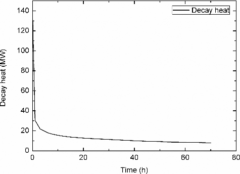
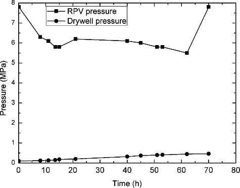
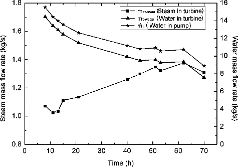
Prior to use the degradation coefficient in the RELAP code, an analytical model of the RCIC system was done in order to estimate the mass flow rates using the TEPCO data [Citation1], the decay heat () and the RPV pressure and the Drywell pressure () during the RCIC operational time. The objective of this analytical model is to estimate the water and steam mass flow rates in the turbine as well as the flow quality x and the water mass flow rate in the pump
The equations used for this analytical model consider the RCIC system as a Rankine cycle, where RPV is the boiler and the suppression chamber is the heat sink. An especial feature of this system is that the turbine is directly connected to the pump forcing the turbine-generated power to be equal to the power received by the pump.
The numerical analysis was made under the assumption that the water level in the RPV remained constant throughout 70 h [Citation1].
First, using the RPV energy balance, the mass flow rate in the RPV
can be calculated
(15)
(15) where
(kg/s) is the mass flow rate in the RPV, Δh is the fluid enthalpy (kJ/kg).
The constant water level in the RPV assumption forces the injected mass flow rate corresponding to the injected water by the RCIC pump and the extracted mass flow rate
corresponding to the water+steam extracted by the RCIC turbine to be the same,
(16)
(16) where
(kg/s) and
(kg/s) are the pump and turbine mass flow rates.
With the mass balance displayed in EquationEquation (16)(16)
(16) , the flow quality x in the turbine included in ηNHEM can be calculated using the pump-turbine power equivalency equation,
Wp = −Wt*ηNHEM,
(17)
(17) where
Wp (kW) and Wt (kW) are the pump and turbine power, Δhs = const (kJ/kg) is the enthalpy difference in the turbine assuming isentropic expansion, H (m) is the pump head, g (m/s2) is the gravity, ηist is the turbine isentropic efficiency, ηshaft is the shaft efficiency and ηp is the pump efficiency.
Then, with the values of x, already found, the water and steam fractions of
can also be calculated. Steam mass flow rate in the turbine can be calculated by the total mass flow rate in the turbine and the flow quality,
(18)
(18) where
(kg/s) is the steam mass flow rate in the turbine.
Once is calculated, the water fraction
of
is the remaining mass. displays the numerical solution of the water in turbine
, steam in turbine
and water in pump
.
3. RCIC RELAP/ScdapSIM analysis
RELAP/ScdapSIM is a severe accident code developed and widely used for best-estimate transient simulation of light water reactor coolant systems during severe accidents.
A steam turbine is a device that converts thermal energy contained in high-pressure, high-temperature steam into mechanical work. In RELAP, the turbine component is modeled and treated as a single junction and volume, then is represented using modified energy, continuity and momentum equations.
3.1. Old (original) turbine model
The turbine power per mass flow unit in RELAP/ScdapSIM, which is included in the fluid momentum equation, is calculated as an efficiency (η) factor times the isentropic enthalpy change across the stage (dh). The enthalpy change can be changed into a pressure change (dp) divided by the fluid density (ρ) [Citation10],
(19)
(19)
If constant efficiency and density are assumed, EquationEquation (19)(19)
(19) can be approximated to EquationEquation (20)
(20)
(20) ,
(20)
(20)
The computed turbine power from EquationEquation (19)(19)
(19) is not only one of the parameters used in the gas and liquid momentum equations for the turbine model but also is used to compute other turbine parameters, such as the torque meaning that any change in the power equation will have a large impact on the overall model behavior [Citation10].
3.2. New (improved) turbine model
For the model improvement, the previous calculated degradation coefficient equation has been applied to RELAP/ScdapSIM source code in addition to the formula used in the code to calculate the turbine power. EquationEquation (19)(19)
(19) becomes
(21)
(21) where W ′ is the new computed power and W is the power calculated in EquationEquation (19)
(19)
(19) . By applying this simple modification to the turbine power equation, the overall momentum equation and all the turbine properties that depend on the power are automatically changed.
3.3. Model setup
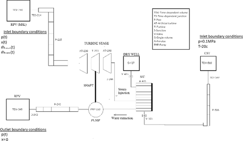
In order to evaluate the turbine model modification effects on the results of the RCIC system simulation under Fukushima accident conditions, a new RCIC nodalization, shown in , has been created.
The RCIC system nodalization used for the simulation includes the RCIC turbine, the pump and the suppression chamber (S/C) as well as the CST and the vacuum breakers.
The first boundary condition is the TEPCO's RPV pressure displayed in , which is a time-dependent variable applied to TDV-210 and TDV-345, which represent the RPV MSL and lower plenum regions, respectively. The second boundary condition applied to these volumes is the flow quality; for TDV-210, the quality is also a time-dependent variable which correspond to the x values calculated in Section 2.4; for TDV-345, the quality is constant and equal to 0 representing that only water is injected to the RPV.
Other time-dependent boundary conditions are the mass flow rates, in the turbine calculated in Section 2.4 and displayed in . These are used in TDJ-214.
The last couple of boundary conditions are applied to the CST represented in the nodalization by the volume TDV-510. The conditions for this volume are a constant pressure and temperature, which represent the fluid conditions inside the tank.
A single-phase period of 8 h of pure steam at the beginning of the simulation was established representing the time before the water reaches the MSL (main steam line) height and starts to flood the turbine then, a two-phase flow is assumed during the rest of the simulation. Also the CST is supposed to work during the first 13 h after the tsunami providing a water mass of 1000 tons to the RPV [Citation1].
3.4. Results and discussion
In this section, a comparison between the unmodified code (old model – no turbine degradation) and the model including the turbine power modification (new model – ηNHEM included) is done displaying the differences between both models under the Fukushima Unit 2 accident conditions.
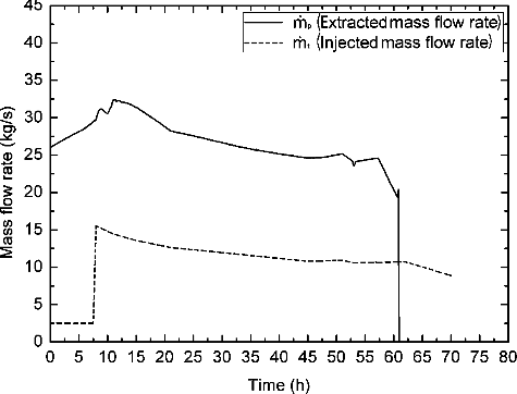
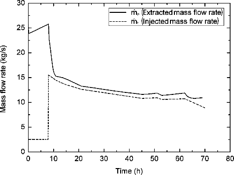
and show the mass flow rate injected by the turbine to the suppression chamber and the mass flow rate extracted by the pump for both, the old and new models.
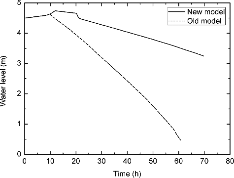
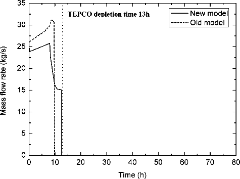
shows a huge discrepancy between the mass flow injected and the mass flow extracted in the old model. The simulation predicts an average value for the mass flow rate around 26 kg/s showing reaching 32 kg/s at t = 11 h once the water starts to move through the turbine. In this figure, a discrepancy between the old model prediction and the TEPCO measurements can be observed; meanwhile TEPCO establish an operation time for the RCIC close to 70 h [Citation1] in the simulation it only last for 60 h. The water mass flow rate is suddenly stopped once the simulation crashed due to the suppression chamber water depletion () and the absence of water to be pumped back to the RPV.
Although the mass should be conserved during the RCIC operation, the simulation with the old model demonstrated that a higher rate of water injection to the RPV is directly related to the overestimation of turbine power. This situation indicates that turbine must have not worked like an ideal turbine. In addition to the isentropic efficiency, another factor must have played a role reducing the turbine power, thereby, reducing the pumped water flow rate into the RPV. Using the TEPCO data [Citation1], the simulation results should be similar to the real accident and have balanced injected-extracted mass flow rates allowing the RCIC to operate during 70 h.
Unlike the old one, the simulation using the new model, utilizing the degradation coefficient, presents a drastic reduction on the amount of water pumped back to the RPV once water starts to flood the turbine at around 8 h. In this case, the simulation ends without stopping the mass flow rate due to the presence of water in the suppression chamber ().
It is interesting to evaluate the meaning of mass flow rate behavior observed in . The fact that both mass flow rates are coupled once the water starts to enter into the turbine after 8 h may lead to suggest that the RCIC system possess some feedback capability. Under these circumstances, a hypothetical increment in the RPV water level will decrease the turbine-generated power causing a reduction of
and, consequently, reducing the RPV water level. The same would happen if the RPV decreased; it would cause a turbine power increment, increasing
and, eventually, raising again the RPV water level.
In other words, once are coupled, the system created by the RCIC cannot be unstabilized by itself. This phenomenon gives a reasonable explanation about why the TEPCO measurements [Citation1] show a constant RPV water level during the RCIC operation time.
The discrepancy between the old and the new model can even be observed during the single-phase period. During that time, the computed power by the new model results in lower values than the old one. The explanation is simple if the turbine is considered as an element where the fluid suffers an expansion from high pressure to low pressure conditions. Due to this expansion, the fluid quality is not constant through the entire turbine (at the end, the fluid quality is lower than at the beginning). This provokes that, even considering pure steam at the inlet of the turbine, the average quality will be slightly under the unity (for example around 95%) which affects the turbine degradation coefficient and causes the small difference observed in computed power values of turbine power during the single phase.
represents the water level in the suppression chamber (S/C). The reason why the simulation using the old model only last for 60 h can be fully explained observing the S/C water level; due to the huge amount of water mass extracted by the pump, the suppression chamber is depleted faster than expected causing the simulation to end once there is no enough water to be pumped.
In the new model, since less water is extracted from the S/C, the water level remains high enough to operate for 70 h.
Other factor that contributes to the water level decrement is the steam generation; hot steam from RPV is being injected in the S/C incremententing the pressure and eventually opening the vacuum breakers to the Drywell to equalize the pressure.
Regarding the CST mass flow rate, shows the amount of time needed by both models to move 1000 tons from the CST to the RPV and compare them with the real time recorded by TEPCO during the accident.
Due to the larger amount of water displaced by the pump in the old model, the 1000 tons are moved faster ending the CST operation time in only 9.8 h. The new model, on the other hand, show a closer value to the real time of 13 h with a difference of 30 min only, ending the CST operation time around 12.5 h
The previous results show how the simulation using the old model has an unexpected mass unbalance between the mass injected by the turbine to the S/C and the mass extracted by the pump from the S/C. That unbalance is caused by the overprediction of the mass of water pumped back to the RPV which causes the CST to last only for 9.8 h and the S/C to be depleted in only 60 h.
In fact, the pump overpredicts the amount of pumped water but the cause of that behavior is the turbine; in the RCIC, the pump is directly connected to the turbine forcing its efficiency to be directly proportional to the turbine performance. In other words, the cause why the pump is pumping more water, and in consequence the S/C is being depleted in only 60 h, relies on the power developed by the turbine.
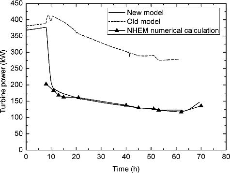
shows the turbine output power calculated by RELAP/ScdapSIM for the old model (before modification) and new model (after modification) comparing them with the turbine power obtained from the RCIC analytical model in Section 2.4.
In the old model curve, a small increment of the power can be observed once the water starts to flood the turbine, probably produced by the increment of the overall mass flow rate caused by the presence of water in the flow. Then, the power starts to decrease mainly due to the pressure reduction between upstream (RPV) and downstream (suppression chamber) but in any moment it is reduced under 250 kW.
The new model, on the other hand, shows a drastic reduction on the turbine power once the water fill inside the turbine, presenting a reduction of 2 or 3 times in comparison of the old model.
4. Conclusions
The NHEM has been used to develop a modification factor for the turbine power called degradation coefficient by comparing the power produced by the maximum flow achievable at a given flow quality. The degradation coefficient quantifies how the output power is reduced as a function of the flow quality.
The resulting formula has been introduced in the RELAP/ScdapSIM source code in order to see its effects on the reproduction of Fukushima Unit 2 accident progression. For the simulation, a RCIC system nodalization has been used and the accident conditions have been reproduced based on the data recorded by TEPCO onsite. The comparison between the simulations results with and without the modification show that the old RELAP/ScdapSIM model overpredicts the turbine power under two-phase flow conditions; generating more power that the pump uses to move higher amount of water and eventually causing the depletion of the suppression chamber before 70 h.
Although the results show a huge divergence once the source code has been modify, there are other phenomena that can influence on the turbine power and should be considered and analyzed in future researches; the torus room flood and the steam flashing. One assumption made after the accident was that the room where the torus is located was flooded by the tsunami, this event changed the conditions (pressure, temperature) inside the suppression chamber which eventually would affect the turbine. The steam flashing is the sudden conversion of the water into steam due to a quick expansion; in RCIC, the pressure difference between upstream and downstream is around 7 MPa that might cause some water to convert into steam an modify the turbine performance.
Disclosure statement
No potential conflict of interest was reported by the authors.
References
- Information portal for the Fukushima Daiichi accident analysis and decommissioning activities. [Internet]. Tokyo: TEPCO; c2012–2015 [cited 2015 May 20]. Available from: https://fdada.info/
- Hoshi H, Ogino M, Kawabe R, et al. MELCOR analysis on Tepco's Fukushima Dai-Ichi NPS accident. Paper presented at: The 15th International Topical Meeting on Nuclear Reactor Thermal - Hydraulics, NURETH-15. NURETH15-653; 2013 May 12–17; Pisa.
- Mizokami S, Yamanaka Y, Watanabe M, et al. State of the art Maap analysis and future improvements on TEPCO Fukushima-Daiichi NPP accident. Paper presented at: The 15th International Topical Meeting on Nuclear Reactor Thermal - Hydraulics, NURETH-15. NURETH15-536; 2013 May 12–17; Pisa.
- Allison CM., Hohorst JK, Allison BS, et al. Preliminary assessment of the possible BWR core/vessel damage states for Fukushima Daiichi station blackout scenarios using RELAP/SCDAPSIM. Science and Technology of Nuclear Installations. New York: Hindawi Publishing Corporation; 2012.
- Okada H, Takahashi A, Suzuki H, et al. Analysis of accident progression of Fukushima Daiichi nuclear power plant with SAMPSON code – (2) unit 2. Paper presented at: The 15th International Topical Meeting on Nuclear Reactor Thermal - Hydraulics, NURETH-15. NURETH15-075; 2013 May 12–17; Pisa.
- Naito M, Suzuki H, Okada H, et al. State of the art SAMPSON analysis and its future improvements for calculations of the Fukushima Daiichi NPP accident. Paper presented at: The 15th International Topical Meeting on Nuclear Reactor Thermal - Hydraulics, NURETH-15. NURETH15-601; 2013 May 12–17; Pisa.
- Takahashi A, Pellegrini M, Suzuki H, et al. Accident analysis of Fukushima Daiichi nuclear power plant unit 2 by the SAMPSON severe accident code. Paper presented at: Proceeding of the 22nd International Conference on Nuclear Engineering, ICONE22. ICONE22-30670; 2014 Jul 7–11; Pague.
- Church EF. Steam turbines.3rd ed. New York (NY): McGraw-Hill Book Company; 1950.
- Elias E, Lellouche GS. Two-phase critical flow. Int J Multiphase Flow. 1994;20:91–168.
- Nuclear Safety Analysis Division. Relap5/Mod3.3 code manual volume I: code structure. Rockville (MD): System Models, and Solution Methods, Inc.; 2001.

