
 ?Mathematical formulae have been encoded as MathML and are displayed in this HTML version using MathJax in order to improve their display. Uncheck the box to turn MathJax off. This feature requires Javascript. Click on a formula to zoom.
Abstract
This paper presents a new method of resonance interference effect treatment using resonance interference factor for high fidelity analysis of light water reactors (LWRs). Although there have been significant improvements in the lattice physics calculations over the several decades, there exist still relatively large errors in the resonance interference treatment, in the order of ∼300 pcm in the reactivity prediction of LWRs. In the newly developed method, the impact of resonance interference to the multi-group cross-sections has been quantified and tabulated in a library which can be used in lattice physics calculation as adjustment factors of multi-group cross-sections. The verification of the new method has been performed with Mosteller benchmark, UO2 and MOX pin-cell depletion problems, and a 17×17 fuel assembly loaded with gadolinia burnable poison, and significant improvements were demonstrated in the accuracy of reactivity and pin power predictions, with reactivity errors down to the order of ∼100 pcm.
1. Introduction
Equivalence theory [Citation1] is widely used for the production calculations of the effective multi-group (MG) cross-sections (XSs) of commercial light water reactors (LWRs). Although there have been many researches to enhance the accuracy of the effective XSs over the decades, modern resonance treatment methods, including equivalence theory, still have relatively large errors in resonance interference model, approximately in the order of ∼300 pcm in the reactivity prediction of LWRs.
Bondarenko iteration method is one of the well-known contemporary resonance interference models [Citation1,Citation2]. The methods introduce non-negligible errors in the effective XSs by simply assuming the absorption XSs of background isotopes flat within each energy group. To improve accuracy with this approach, the resonance energy groups need to be refined sufficiently like ultra-fine group (UFG) method. However, the UFG approach is not a viable option for daily production work due to its massive consumption of computational resources. Lee applied the UFG method to fast reactor analysis, but the method simplifies geometries for computational efficiency [Citation3]. A long mean-free-path of fast reactor makes it possible to get reasonable results even with the geometry simplification. For LWRs, Sugimura applied UFG collision probability method to solve slowing-down equation and then calculate the MG XS using the spectrum but the collision probability method was limited to a simple pin-cell geometry, and still non-negligible computer resources were required [Citation4]. In order to reduce the requirements of computational resources in solving the UFG slowing-down equation, Knott and Koike used narrow resonance and intermediate resonance approximations in neutron energy spectrum to generate a correction factor, respectively [Citation5,Citation6], which could also introduce errors in the MG XSs. Lee applied a continuous energy Monte Carlo method to the resonance energy range of deterministic code in order to enhance the accuracy [Citation7].
In this paper, a new resonance interference method is presented which uses the resonance interference factor (RIF). Unlike Mark's RIF method [Citation8], the new method interpolates RIFs in a pre-generated RIF library (RIFL) and then uses the factors for the effective XS adjustment, rather than performing the time consuming on-the-fly slowing-down calculation. Peng and Kim also used a similar approach, i.e., the use of pre-generated adjustment factors or pre-generated MG XS library with interfering isotope. But this approach treats interference effect between 235U and 238U only due to the limitation of the number of isotopes caused by the huge size of library [Citation9,Citation10]. The issues in the previous research works have been resolved by the resonance treatment method with RIFL developed in this paper. The pre-generated RIFL contains information of 40 resonance absorbers, which are sufficiently many resonance isotopes to analyze LWR depleted lattices. The RIFs are interpolated in the library with the background XSs and atom ratios, and then used to correct the resonance interference effect. An approximation is introduced to reduce the size of library and minimize the increase of execution time. Preliminary studies were performed in order to develop this new resonance interference method [Citation11,Citation12]. In the studies, detailed descriptions for the RIFL and methods were not presented, and verifications were performed for limited problems such as homogeneous mixture and pin cell. In this paper, the RIFL has been upgraded to analyze various fuel types, and detailed methods for the RIFL generation and application are described. The new method has been implemented in the lattice physics code STREAM [Citation13–15], and its accuracy is compared with the conventional resonance interference model. From the benchmark calculations of LWR pin cells and assembly, the STREAM with the RIFL shows significant improvements of accuracy in the reactivity, reaction rates, and power distribution.
2. Conventional methods of resonance interference treatment
2.1. Conventional resonance interference model
In the conventional equivalence theory [Citation1], the effective XS of a target resonance isotope is computed first by assuming that only the target resonance isotope has absorption XS. Other resonance isotopes are assumed to have the potential scattering XS only. The effective XSs of resonance isotopes are re-evaluated in order to consider the resonance interference effect among resonance isotopes after the first-step XSs of all isotopes in a fuel material are computed. The absorption XSs of other resonance isotopes are added to the background XS of the target resonance isotope. If the one-term rational approximation is applied, the effective absorption XS is computed as follows:
(1)
(1) where RIia is an absorption resonance integral per unit lethargy, σib is a background XS of isotope i, σia is an absorption XS, and
is an absorption XS of other resonance isotopes which is defined by
(2)
(2) where Ni is a number density of isotope i.
As a result of the interference treatment by the conventional equivalence theory, the effective XS of the isotope always increases due to the increase of background XS, which could be inconsistent with reality depending on compositions. One of the conventional methods, Bondarenko iteration method adopts an iterative procedure of EquationEquations (1)(1)
(1) and (Equation2
(2)
(2) ) until all the effective XSs converge [Citation2].
2.2. Drawback of the conventional equivalence theory
The conventional resonance interference model assumes that the absorption XSs of the other resonance isotopes are constant within the corresponding energy group. This assumption can cause significant errors in the effective XS for some cases depending on compositions. The resonance interference occurs in a very complicated manner and, for the accurate treatment of the interference, a point-wise (PW) or UFG neutron energy spectrum calculations are needed. It is also important to consider the relative locations of interfering resonance peaks in the spectrum calculations.
Three 0-D homogeneous problems are designed to demonstrate the complexity of the resonance interference effect. Three material compositions in temperature 293.6 K are considered as follows (atom number density in #/barn-cm and isotope name): case 1 has 2.00 1H and 1.00 238U, case 2 has 0.04 239Pu in addition to case 1, and case 3 has 0.04 240Pu in addition to case 1. The resonance interference effect from Pu isotopes to 238U is quantified by evaluating the amount of changes of 238U XS.
shows the UFG spectra, obtained by in-house UFG slowing-down solution code with fixed sources at high energy, and the capture XSs of U and Pu isotopes. The variations of the effective XS depending on the interfering isotopes are closely related to the UFG neutron energy spectrum. Flux spectrum of case 1 shows a dip around the peak of the resonance of 238U isotope. When the 239Pu is added to the mixture in case 2, additional flux drops occur. The dips caused by the 239Pu resonances are away from the 238U resonance peak. The 238U capture XS of case 2 between 16 and 27.7 eV by EquationEquation (3)(3)
(3) increases due to the additional dips from 239Pu:
(3)
(3) where x represents a reaction type, u is an index of UFG, g is a group index, σx, g is an effective XS, and φu is UFG flux.
Figure 1. UFG flux spectrum and XSs.
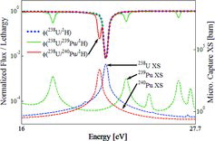
In contrast with case 2, it should be noted that the 240Pu resonance peak in case 3 is close to the 238U resonance, and the 240Pu resonance makes a flux dip near to the 238U resonance. The close flux dip corresponding to 240Pu resonance causes the reduction of flux weighting on 238U resonance peak, and consequently, it causes the reduction of 238U effective XS.
In case 1, the 238U capture XS is 6.10 barns. The microscopic capture XS is calculated with EquationEquation (3)(3)
(3) . In case 2, the 239Pu added into the mixture increases the 238U XS upto 6.33 barns by the resonance interference. However, when 240Pu is added in case 3 instead of 239Pu, the 238U XS decreases down to 5.85 barns. The 240Pu resonance interference effect causes the reduction of 238U capture XS.
It is noted that, through cases 1–3, the resonance interference does not always cause the increase of XSs as expected from the conventional interference method. It depends on the overlap/no overlap of the resonances, i.e., the relative locations of resonances. If the resonances do not overlap each other, the resonance interference effect leads to the increase of MG XS. On the contrary, if the resonances overlap each other, it causes the reduction of MG XS. In order to model the resonance interference effect accurately, the UFG or PW flux calculation should be used for the weight spectrum calculations because there is no way to know how the resonances overlap unless the detail XS variations in the group is taken into account. In the conventional resonance interference model, the resonance interference effect always increases the MG XS, which is not true. Even when the resonance interference effect actually increases the effective XS, the conventional method still cannot predict the accurate magnitude of the interference effect because of the constant absorption XS assumption.
2.3. Conventional resonance interference factor method
The RIF method [Citation8] was proposed in order to solve the drawbacks of the conventional resonance interference model. The RIF fix, g is defined as a ratio of two MG XSs of the target isotope. One is the MG XS of the target isotope in a fuel mixture, and another is the XS of the target which is separated from the other resonance absorbers as follows:
(4)
(4) where x is a reaction type, g is a group index of MG, u is a group index of UFG, and i is an index of the resonance absorber.
The UFG flux calculation is performed to compute the RIFs. The RIFs are used to correct the effective XS to take into account the resonance interference effect as follows:
(5)
(5) where σix, g is the effective XS generated by equivalence theory without considering resonance interference effect and
is a corrected effective XS by RIF.
The neutron transport codes which adopt conventional RIF method perform the on-the-fly UFG slowing-down calculation to compute the RIF, which requires significant amount of computational resources depending on the calculation methods [Citation5,Citation16,Citation17,Citation18]. In order to reduce the execution time, there have been attempts to compute the flux spectrum with narrow and intermediate resonance approximations [Citation5,Citation6]. However, the approximations introduce errors compared to the solutions of the UFG slowing-down calculations.
3. New resonance interference factor method
3.1. Resonance interference factor library
The RIFL method has been developed to overcome the drawbacks of the conventional RIF method. The new RIFL method adopts the concept of RIF but the difference from the conventional method is that the RIFs are pre-generated in a similar format of MG XS library. An in-house computer code which solves the UFG slowing-down problem has been developed and used to generate the RIFL. The code uses 48,070 energy groups (0.3 eV to 10 MeV) and the asymptotic elastic scattering kernel has been adopted. The RIFL is generated by solving 0-D slowing-down equation in EquationEquation (6)(6)
(6) :
(6)
(6) where
is a macroscopic scattering XS from UFG u′ to u, Σt, uis a macroscopic total XS, and φu is a flux in UFG u.
In the slowing-down calculation, an initial source is set to non-zero arbitrary value at the highest energy group. Although fission spectrum can also be used as a source, the impact of the difference in sources is negligible since there is very small amount of fission neutrons in the resonance energy range. Hydrogen is chosen as moderator material, since the hydrogen is the most dominant moderator in LWR design.
The RIF is tabulated as a function of background XS, temperature, and the number density ratios of resonance absorbers. The RIF table is prepared for each energy group and reaction type. The specification of the RIFL is summarized in
Table 1. RIF library specification.
The RIFL is generated for dominant resonance absorbers with respect to the reactivity in the resonance energy range and resonance interference effect. Total 40 resonance absorbers have been selected through sensitivity tests based on LWR design. There are three categories of resonance isotopes in the RIFL, according to the number density behavior and usage. The categories are used to divide the grids of background XSs and number density ratios. Category A has only 238U which is the most dominant isotope in fuel materials of LWRs. The order of magnitude in the number density and background XS of 238U are quite different from the other isotopes. Category B contains isotopes in UO2, MOX fuels, and gadolinia burnable absorber at beginning of cycle (BOC). Category C has fission products and actinides which are generated in depletion. The number densities of all isotopes in the category C are usually smaller than those in the categories A and B. The background XS grids are determined based on the behaviors of each category. The number of grids of the background XSs is 10. The grid values of background XSs are shown in
Figure 2. Grid of background XS for each category.
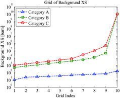
The background XS of 238U is about 60 barns for a typical LWR pin cell when the one-term rational approximation is applied, and its variation is small in LWRs. For the two- or three-term approximation, the background XS of 238U for each term may usually be 20–200 barns. For the actual background XS treatment in terms of the RIF interpolation of the present method which is described in Section 3.2, the equivalent one-term background XS is applied in order to reduce a range of the background XS. Therefore, the background XS grids are concentrated around 60 barns for the isotope in the category A. The isotopes in category B have a few hundreds to a few thousands barns of background XSs in the fuel at BOC, and the number densities decrease as the fuel region depletes. Therefore, it is needed to cover a wider range of background XSs for category B. The isotopes in the category C require larger background XSs than those of the category B because of its smaller number densities. The method to choose the background XS grid values is similar to that of the MG XS library [Citation17].
The next important parameter of RIF is the number density ratio between resonance absorbers. The resonance interference effect increases when there exists more resonance isotopes in the fuel mixture, i.e., the enrichment of fuel and the kinds of resonance absorbers are important parameters affecting the magnitude of the interference effect. The concept of RIFL is that the resonance interference effect is calculated in advance before the actual LWR analysis with lattice physics code. It is a challenging task to generate the RIFL for all possible combinations of resonance isotopes. When the number of resonance absorbers increases, e.g., highly depleted fuel, the number of combinations of resonance interferences increases dramatically. It is not only difficult to generate RIFL for all the combinations of resonance absorbers, but the size of library will become too large. Therefore, the RIFL method in this paper takes into account only one-to-one interaction between two resonance absorbers, and the total resonance interference effect is calculated by summing up individual interference effects. The RIFL contains information of one-to-one interference effect. The total number of resonance absorbers in the library is chosen to be 40. Therefore, the number of combinations of two resonance absorbers is 40 × 39 = 1560. For each combination, the total number of density ratios, 20, is used in the RIFL. The grid values of the ratios are chosen according to the characteristics of each category. shows the grids of ratios for different categories.
Figure 3. Grid of number density ratio for combinations.
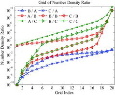
In , ‘B/A’ means the number density ratio of the category B to category A. In LWR fuels, the number density of category A (only 238U) is much larger than that of other categories. Therefore, ‘B/A’ and ‘C/A’ have values lower than 1 for all grid points. ‘B/B’ and ‘C/C’ mean the ratios between isotopes in their own category. For example, the ratio grids between 235U and 239Pu belong to ‘B/B’. There is no ‘A/A’ because the category A has 238U only. Other ratios are also determined by considering probable number densities of each category in LWR fuels.
The remaining parameters from are the energy group, reaction type, and fuel temperature. The RIFs are generated for 15 resonance energy groups (4 to 2.478E+04 eV) since the lattice physics code STREAM uses 15 resonance energy groups. In case of the resonance absorbers with resonances below 4 eV, STREAM uses an extended resonance energy range (0.3 to 4 eV), and applies the resonance treatments to those isotopes [Citation13]. The RIFL contains RIF information in the 24 extended resonance groups for corresponding resonance absorbers.
The RIFs are generated according to reaction types such as capture, fission, and scattering, the XSs of which are different from each other. Therefore, the interference effect is also different. Temperature can also have impact on the resonance interference effect because of broadened resonance XS according to temperatures. However, a sensitivity study of RIF to temperature shows small impact. Therefore, the RIFL has only three temperatures: 293.6, 600, and 900 K.
Using the pre-generated RIFL, the RIF of LWR lattice for target resonance isotope i interfered by resonance isotope j, atom ratio γ, background XS σi0, reaction type x, energy group g, and temperature t is calculated as follows:
(7)
(7) where σi, mixx, g, t(γ, σ0i) is a MG XS of isotope i in the mixture of isotopes i, j, and hydrogen; σi, isox, g, t(σ0i) is a MG XS of isotope i in the mixture of isotope i and hydrogen; σix, u, t is a UFG XS of isotope i; φi, ju, t(γ, σ0i) is a flux in the mixture of isotopes i, j, and hydrogen; and φiu, t(σ0i) is a flux in the mixture of isotope i and hydrogen.
The background XS σi0 of target isotope i is defined as the macroscopic potential scattering XS of hydrogen (ΣHp) divided by the number density of isotope i (Ni):
(8)
(8)
It should be noted that the background XS in EquationEquation (8)(8)
(8) does not include the XS from the resonance isotope j in order to prevent from double count to consider the interfering isotopes. The interfering isotope is counted in the number density ratio.
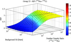
RIF is calculated by using EquationEquation (7)(7)
(7) and tabulated in the library. and show RIFs for 239Pu and 240Pu interfered by 238U, respectively. As shown in the figures, RIFs vary depending on the background XS and the number density ratio. In the RIFL, the number density ratio is defined as the ratio of the number densities of interfering isotope j to that of the target isotope i (
). The RIFs of both 239Pu and 240Pu become unity when the background XS increases and/or the ratio decreases. When the background XS is very large and the ratio is small, the flux depression by interfering isotope is negligible. In this case, the RIF value goes to unity. On the other hand, the interference effect becomes larger when the ratio increases and the background XS decreases. As described in Section 2.2, the resonance interference effect can increase or decrease the effective XS depending on how the resonances are overlapped within the energy group. In the energy group between 15.968 and 27.7 eV, the resonances of 239Pu and 238U are not closely overlapped each other. The flux depression by interference resonance absorber increases the weighting on the resonance peak of target isotope. Therefore, the RIF values of 239Pu interfered by 238U are larger than 1.
Figure 4. Capture reaction RIF of 239Pu interfered by 238U (group 25: 15.968 to 27.7 eV).
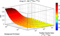
Figure 5. Capture reaction RIF of 240Pu interfered by 238U (group 25: 15.968 to 27.7 eV).
On the other hand, the resonances of 240Pu and 238U are closely overlapped in the energy group of 15.968 and 27.7 eV, and therefore, the flux depression by 238U decreases the flux weighting on the 240Pu resonance peak, which eventually reduces the 240Pu effective XS.
3.2. New resonance interference treatment method with RIF library
The new resonance interference treatment method with RIFL is described in this section. The method is based on the equivalence theory. In the equivalence theory, the fuel-to-fuel collision probability, Pff, g, or the fuel escape probability, Pe, g, for energy group g are approximated by rational expression as follows:
(9)
(9) where αl, g and βl, g are coefficients of lth term of the rational expression, Xg is an optical length which is defined as the ratio of total XS to escape XS (
), and L is the total number of terms of rational approximation.
STREAM uses the optimum rational approximation method, where the coefficients of rational expression are computed through fixed source calculation with method of characteristics (MOC) transport solver, and the least square fitting process, rather than using the conventional rational approximation with Dancoff factor [Citation13]. The effective XS of target isotope i is derived as EquationEquation (10)(10)
(10) by using the fuel-to-fuel collision probability [Citation1,Citation17]:
(10)
(10) where RIix, g is a resonance integral per unit lethargy for reaction type x, the temperature index t is omitted for brevity, and the background XS σib, l, g is defined as follows:
(11)
(11) where λig is an intermediate resonance parameter and σip is a potential XS.
The background XS is composed of the potential XS of isotopes in the fuel lump and the escape XS. The background XS can be defined in two ways as shown in EquationEquation (11)(11)
(11) . If the target isotope i is included in the RIFL, the other resonance absorbers in the RIFL are not included in the background XS. In this case, the RIF will consider both the scattering and absorption effects. If the target isotope i is not included in the RIFL, all isotopes in the fuel region are included in the background XS. In this case, resonance interference effect on the isotope i is ignored, and the following resonance interference treatment is not performed.
Once the effective XS of target isotope i is calculated by EquationEquation (10)(10)
(10) , the RIF
of target i interfered by absorber j is interpolated in the RIFL with the equivalent background XS
and the number density ratio γ. A log–log–linear interpolation scheme is applied to the parameters
, γ, and fi ← jx, g in sequence. The equivalent background XS
is calculated by EquationEquation (12)
(12)
(12) using log–log interpolation in the MG XS library as follows:
(12)
(12) where σi, mx, g is x reaction XS corresponding to the background XS σi, mb, g in the XS library, m is an index for background XS grid, and σi, mx, g ⩽ σx, gi < σi, m + 1x, g.
It should be noted that the equivalent background XS of target i in EquationEquation (12)(12)
(12) does not include its potential XS, λigσpi. It is because the definition of background XS in the RIFL, σi0 in EquationEquation (8)
(8)
(8) , does not include the background XS of target isotope itself.
The individual RIF fi ← jx, g of target isotope i is interpolated for all resonance isotopes j in the RIFL (j ∈ RIFL). The interpolated RIFs are used to compute variations of the effective XS from the interfering isotope j as follows:
(13)
(13)
In EquationEquation (13)(13)
(13) , the total resonance interference effect on the target isotope i from other resonance absorbers is calculated for all the individual one-to-one resonance interference effects. The effective XS σix, gin EquationEquation (10)
(10)
(10) is corrected by adding Δσix, g as follows:
(14)
(14)
Consequently, the final expression of the effective XS, , takes account for all the resonance interference effects from all the other resonance absorbers. The scattering matrix is normalized to be the corrected scattering XS.
The resonance self-shielding method with the RIFL has been proposed based on the equivalence theory, where the background XS from interfering resonance absorber in the RIFL is not included in the total background XS, σib, l, g, as described in EquationEquation (11)(11)
(11) . Although the RIFL method is based on the equivalence theory, the method can also be applied to other resonance treatment methods such as the subgroup method or the embedded self-shielding method.
Since the new RIFL method uses simple interpolations and does not need iterative calculations such as the Bondarenko iteration method, the increase of execution time is negligible, and the size of ASCII formatted RIFL is just 140 MB per temperature. It is also possible to further reduce the library size by omitting the self-shielding treatment of scattering XS and/or reducing the grid points in temperature since the RIF's sensitivity to temperature is small. Although the detail sensitivity tests for temperature are not presented in this paper, it has been confirmed that the 300 K intervals in the RIFL is sufficient to achieve reasonable accuracy.
The RIFL generated from the 0-D homogeneous system neutron spectrum can be applied to both homogeneous and heterogeneous problems since the background XS plays a role as a bridge between homogeneous system and heterogeneous system. Therefore, the application of new RIFL method is not limited by the geometry of problems as long as appropriate background XSs can be defined.
4. Verifications
4.1. Summation approximation in RIF library method
In the RIFL method, the total resonance interference effect is approximated as the sum of each individual effect as described in EquationEquations (13)(13)
(13) and (Equation14
(14)
(14) ), i.e., the cross-terms of the interference effects are ignored. This approximation will be called as a ‘summation approximation’ hereafter. The errors introduced by the summation approximation will be quantified using the in-house 0-D UFG calculation program.
For the investigation of the summation approximation, a simple homogeneous problem was designed with the material composition in . The composition is obtained from a typical LWR pin-cell model at burnup 60 MWd/kgU, and only actinides and hydrogen are considered. On top of that, the number density of hydrogen in the mixture is increased to make a similar condition of the homogeneous problem with a typical heterogeneous pin-cell problem in terms of the magnitude of background XS considering the omitted isotopes and escape XS. The purpose of this verification is to evaluate accuracy of the summation approximation in computing the total resonance interference effect. In case of fresh fuel, there are few kinds of resonance absorbers such as 235U and 238U. In this case, there is no possibility that the summation approximation causes error because the total interference effect is exactly same as individual interference effect. That is why highly depleted fuel is selected in the verification which is the most complicated situation in terms of the resonance interference.
Table 2. Number density of homogeneous problem.
compares the 238U capture XSs calculated from three different methods. First, ‘UFG’ indicates the reference XSs from a UFG fixed source calculation with all isotopes included together, and ‘Isolated’ means that the XS is calculated from a UFG fixed source calculation but with 238U/1H mixture only. The differences of the two XSs represent the amount of interference effects. ‘RIF’ indicates the XSs corrected by the summation approximation. It should be noted that there are significant differences between the XSs of ‘UFG’ and ‘Isolated’, as high as 3.919%, which is the resonance interference effect by other resonance absorbers, and the summation approximation can reduce most of the differences. The maximum difference decreases down to 0.058%, which verifies the validity of the summation approximation.
Table 3. 238U capture XSs of homogeneous problem.
4.2. Mosteller pin-cell benchmark
A well-known Mosteller pin-cell benchmark [Citation19] consists of UO2 fuel, reactor-recycle MOX fuel, and weapons-grade MOX fuel. Each type of fuel has variations of enrichments in hot zero power (HZP) and hot full power (HFP) conditions of LWRs; therefore, the benchmark is suitable for verification of the new resonance treatment method. The lattice physics code STREAM is used in the following verifications. STREAM uses advanced resonance treatment methods as well as MOC transport solver and acceleration techniques [Citation20]. The benchmark problems are summarized in . MCNP6 [Citation21,Citation22] is used to generate reference data. All results of STREAM and MCNP6 in this paper were generated by using ENDF/B-VII.0 nuclear data [Citation23]. STREAM uses three types of methods for the resonance interference effect treatment as follows:
NC: no correction of resonance interference effect,
BI: Bondarenko iteration method described in Section 2.1, and
RIFL: RIF library method described in Section 3.
Table 4. Descriptions of Mosteller benchmark.
The reference infinite multiplication factor (k-inf) values are shown in at both HFP and HZP conditions. The 1σ standard deviations of MCNP results are less than 3 pcm. and show the differences of k-inf from the MCNP reference at HZP and HFP, respectively. The results at HZP and HFP show similar behavior.
Figure 6. Reference k-inf from MCNP6 (Mosteller benchmark).
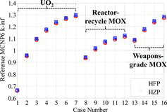
Figure 7. Comparison of k-inf for Mosteller benchmark (HZP).
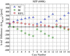
Figure 8. Comparison of k-inf difference for Mosteller benchmark (HFP).
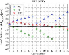
For UO2 fuel problems (cases 1–7), NC shows 64–259 pcm over-predictions in k-inf. The k-inf difference increases as the enrichment increases. A similar behavior is observed for both reactor-recycle (cases 8–12), and weapon-grade MOX fuels (cases 13–16). The differences of k-inf vary from 70 to 334 pcm for the reactor-recycle, and 153 to 380 pcm for the weapon-grade MOX fuel. The bias as a function of enrichment or Pu content is caused by resonance interference effect of the resonance absorbers in the fuel. When the BI method is applied to treat the resonance interference effect, the magnitude of the bias is similar to that of NC but the sign changes from positive to negative. The BI method shows always smaller k-inf compared to NC because the adjustment of 238U XSs by the BI method is always the increase of XSs as described in Sections 2.1 and 2.2. The BI method shows 1–270 pcm differences in k-inf for UO2 fuel and 6–335 pcm for MOX fuels. This method tends to overestimate the interference effect, i.e., decrease k-inf too much. On the other hand, STREAM with RIFL shows significantly improved results. The RIFL method shows less than 100 pcm differences in k-inf for most cases. The maximum difference is 119 pcm. There is still a small bias in k-inf as a function of enrichment, which is insignificant. summarizes Mosteller benchmark analyses. For all the HZP and HFP problems, the RIFL method shows a 64 pcm root mean square (RMS) average k-inf difference. The BI method shows little improved k-inf results compared to that of NC. The RMS k-inf differences are 223 and 157 pcm for NC and BI methods, respectively. The RIFL method also shows a smaller standard deviation of the k-inf differences compared to the other two methods. The RIFL method gives not only accurate results, but also consistent results. The BI method has the largest standard deviation among three methods. The RIFL method shows than three times more accurate results in terms of the maximum k-inf difference.
Table 5. Summary of Mosteller benchmark analyses (32 cases).
4.3. UO2 and MOX pin-cell depletion problems
UO2 and MOX pin-cell depletion problems are designed to verify the RIFL method. The models are same as 5 wt.% enriched UO2 fuel (case 7 in ) and 8 wt.% PuO2 content reactor-recycle MOX fuel (case 12 in ) pin-cell problems at HFP in Mosteller benchmark. The two pin cells are depleted upto 60 MWd/kgU with the power density of 31 W/gU in 34 burnup steps. It should be noted that these problems are designed to verify the resonance interference treatment of STREAM, not the depletion chain and method. Therefore, the depletion calculations are only performed by MCNP6, and isotopes of each burnup step are extracted and used as inputs for STREAM. All the isotopes in ENDF/B-VII.0 neutron data are considered in the MCNP depletion calculation.
and show the results of the pin-cell depletion analyses. It is noted that NC and BI show significant bias as a function of burnup. In , the two methods show about 100 pcm swings in the k-inf differences between 0 and 10 MWd/kgU burnups. After 10 MWd/kgU burnup, the two methods maintain their levels of differences which are ∼350 pcm for NC and ∼200 pcm for BI. On the other hand, the two methods have more significant swings in the k-inf difference for MOX fuel in . The k-inf differences vary from around 300 to 600 pcm for NC and from 330 to 180 pcm for BI. The two methods show inaccurate and inconsistent behaviors in the k-inf difference. Then, the RIFL method shows significant improvements in the accuracy of k-inf for both UO2 and MOX fuels. The maximum differences of k-inf are just 66 pcm for UO2 fuel and 77 pcm for MOX fuel. There is no significant bias or swings observed in the results. The RIFL method shows quite accurate and consistent results. The results are summarized in and . The RIFL method shows superior results compared to the previous two methods in terms of the RMS k-inf difference, the standard deviation of k-inf differences, and the maximum k-inf difference. The BI method improves the results a little compared to NC and has still significant differences in the results.
Figure 9. Comparison of k-inf difference for UO2 pin depletion problem.
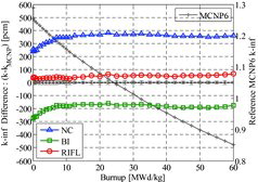
Figure 10. Comparison of k-inf difference for MOX pin depletion problem.
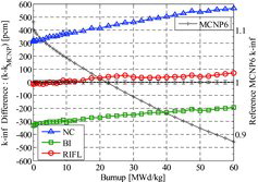
Table 6. Results of UO2 pin depletion problem analysis.
Table 7. Results of MOX pin depletion problem analysis.
For detail analyses, reaction rate comparison is performed at end of cycle (EOC) (60 MWd/kgU) of UO2 fuel depletion problem using the following equation:(15)
(15) where P is total production reaction rate corresponding to nu × fission, A is total absorption reaction rate, and Pr, i, g and Ar, i, g are production and absorption reaction rates of isotope i in each region r and energy group g, respectively.
EquationEquation (15)(15)
(15) is valid when the absorption reaction rates of MCNP and STREAM are normalized to be 1. It is possible to identify the magnitude of impact to the difference of k-inf from the difference of a specific reaction rate between the MCNP references and the STREAM results. shows the reaction rate comparison results of total 11 selected isotopes in fuel region and resonance energy range. The reaction rate difference from other isotopes is not significant and can be ignored in the resonance energy range. The NC has 470 pcm difference for 238U, and has also significant differences for other actinides and fission products. The BI reduces the k-inf difference caused by 238U, by increasing the absorption XS with the interference effect. The BI method improves the accuracy of reactivity impact of 238U by ∼300 pcm. However, it still has about 110 pcm difference. A similar behavior is noted for 241Pu reaction rate. The BI method is not effective for other actinides. If NC has positive difference in the reaction rate, then the BI method can improve the results. However, if the original difference is negative, the BI method cannot improve it, rather the method increases bias in each reaction rate of isotopes such as 235U, 236U, and 239Pu. It should be noted that an exceptional case can occur when some other resonance absorbers cause significant flux change. In other words, an absorption XS increase cannot guarantee an absorption reaction rate increase. For example, when applying the BI method, 238U XS increases and the flux is depressed so significantly that 240Pu absorption reaction rate decreases even the 240Pu effective XS increases slightly.
Figure 11. Difference of k-inf from reaction rate difference in resonance energy range (UO2 fuel at 60 MWd/kgU burnup).
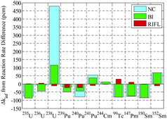
For the fission products, the BI method does not show any improvements at all. The number density of fission products is relatively small compared to that of actinide. Therefore, the background XSs of fission products are larger than 104 barns while that of 238U is just 60 barns. The magnitude of effective XS increases as the background XS increases, and the effective XS approaches to saturated values at the high background XSs. Therefore, if fission products already have the saturated effective XSs, the increase of the background XSs by the BI method cannot improve the effective XSs, which is the reason why the results of two conventional methods, NC and BI, show similar results for fission products. The next issue to be noteworthy is that those fission products (i.e., 99Tc, 147Pm, and 150Sm) have negative reaction rate differences with the NC method. It means that the reduction of effective XS is needed to take into account the interference effect. However, the BI method always increases the effective XSs. Although several significant inherent drawbacks of BI method are identified from the detail reaction comparisons, the BI method still shows reasonable results in the final k-inf, which can be attributed to the error cancelations. However, the errors in detail reaction rates can introduce errors in the depletion calculation, if STREAM performs its own depletion calculation. The RIFL method can resolve such problems effectively. The RIFL method computes the interference effect in the right directions and accurate amount for most isotopes, e.g., the maximum reaction rate difference is 29 pcm for 99Tc. It is noted that the new method is effective in treating interference effect for fission products as well as for actinides.
4.4. 17 × 17 fuel assembly problem
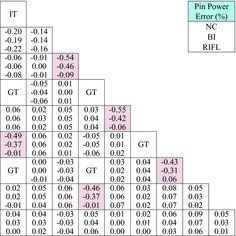
As a last verification problem, a 17 × 17 type LWR fuel assembly (FA) problem is selected from the FA problem-2P of VERA benchmark [Citation24]. In both STREAM and MCNP6 models, the assembly inter-gap is ignored for simplification. The modified assembly pitch is 21.42 cm by removing the inter-gap. summarizes the results of FA analyses. and show the pin power distributions of MCNP6, and differences of STREAM results, respectively. The NC method shows 50 pcm k-inf difference and 0.19% RMS difference of pin power distribution. The maximum pin power difference of 0.55% is noted in a gadolinia poisoned rod. The BI method shows larger k-inf difference, 280 pcm in the negative direction. The BI method slightly improves the pin power distribution. The RIFL method shows the most accurate results of k-inf and power distributions, with the k-inf difference of 28 pcm. The k-inf values can be either increased or decreased when the interference effect is modeled correctly, while the BI method tends to reduce k-inf due to the trend of positive bias for effective XS. The difference of pin power of the RIFL method is 0.06% on the average and 0.22% in the maximum. The RIFL method significantly improves the pin power predictions, especially for gadolinia poisoned rods. The FA analysis in this section demonstrates that the RIFL method can be applied to the FA problems with significant improvements in the reactivity and pin power distributions.
Table 8. Result of 17 × 17 fuel assembly analyses.
Figure 12. Pin power distribution of 17×17 fuel assembly of MCNP (octant symmetry).
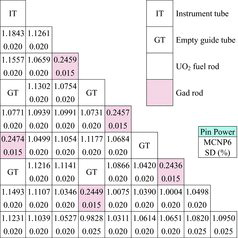
Figure 13. Difference of pin power distribution (octant symmetry).
5. Conclusions
A new resonance self-shielding method using the RIFL has been developed to accurately model the resonance interference effect. In this method, the magnitude of individual isotope-to-isotope resonance interference effect is quantified with UFG calculation in a homogeneous mixture, and the RIFs are tabulated in a library as a function of parameters such as background XS and the ratio of isotopic number densities. The formulation of new equivalence theory with the RIFL has been derived and implemented in the lattice physics code STREAM. The accuracy of the new technique has been verified in various conditions of LWR with a depleted homogenous mixture problem, the Mosteller pin-cell benchmark, UO2/MOX pin-cell depletion problems, and a gadolinia-bearing 17 × 17 FA problem. The verification results demonstrate that STREAM with the RIFL can produce accurate results of k-inf, reaction rate, and power distribution. This method overcomes successfully the drawbacks of conventional resonance interference models. The new RIFL method shows significant improvements in the accuracy for complicated resonance interference effects without loss of computational efficiency.
Disclosure statement
No potential conflict of interest was reported by the authors.
Additional information
Funding
References
- Stamm'ler RJJ, Abbate M. Methods of steady-state reactor physics in nuclear design. London: Academic Press; 1983.
- Bondarenko II, editor. Group constants for nuclear reactor calculations. New York (NY): Consultants Bureau; 1964.
- Lee CH, Yang WS. MC2-3: multigroup cross section generation code for fast reactor analysis. Lemont (IL): Argonne National Laboratory; 2012. (ANL/NE-11-41).
- Sugimura N, Yamamoto A. Resonance treatment based on ultra-fine-group spectrum calculation in the AEGIS code. J Nucl Sci Technol. 2007;44(7):958–966.
- Knott D, Wehlage E. Description of the LANCER02 lattice physics code for single-assembly and multibundle analysis. Nucl Sci Eng. 2007;155(3):331–354.
- Koike H, Yamaji K, Kirimura K, et al. Quantification of resonance interference effect for multi-group effective cross-section in lattice physics calculation. In: Suyama K, Sugawara T, Tada K, Chiba G, Yamamoto A, editors. Proceedings of the international conference on physics of reactors (PHYSOR 2014); 2014 Sep 28–Oct 3; Kyoto. Tokai: Japan Atomic Energy Agency; 2015. (Report no. JAEA-Conf 2014-003 appendix CD-ROM).
- Lee H, Choi S, Lee D. A hybrid Monte Carlo/method-of-characteristics method for efficient neutron transport analysis. Nucl Sci Eng. 2015;180:69–85. Available from: http://dx.doi.org/10.13182/NSE13-102
- Williams ML. Correction of multigroup cross sections for resolved resonance interference in mixed absorbers. Nucl Sci Eng. 1983;83(1):37–49. Available from: http://dx.doi.org/10.13182/NSE83-2
- Peng S, Jiang X, Zhang S, et al. Subgroup method with resonance interference factor table. Ann Nucl Energy. 2013;59:176–187. Available from: http://dx.doi.org/10.1016/j.anucene.2013.04.005
- Kim KS, Hong SG. A new procedure to generate resonance integral table with an explicit resonance interference for transport lattice codes. Ann Nucl Energy. 2011;38:118–127. Available from: http://dx.doi.org/10.1016/j.anucene.2010.08.005
- Choi S, Khassenov A, Lee D. Improvement of resonance interference treatment in STREAM. Paper presented at: KNS Fall Meeting; 2014 Oct 30–31; Pyeongchang.
- Choi S, Khassenov A, Lee D. Resonance interference method in lattice physics code STREAM. In: Matsuura S, Arastu A, Lei Z, editors. Proceedings of the 23rd International Conference on Nuclear Energy; 2015 May 17–21; Chiba: Japan Society of Mechanical Engineers; 2015.
- Choi S, Lee H, Hong SG, et al. Resonance self-shielding methodology of new neutron transport code STREAM. J Nucl Sci Technol. 2015;52(9):1133–1150. Available from: http://dx.doi.org/10.1080/00223131.2014.993738
- Choi S, Smith K, Lee HC, et al. Impact of inflow transport approximation on light water reactor analysis. J Comput Phys. 2015;299:352–373. Available from: http://dx.doi.org/10.1016/j.jcp.2015.07.005
- Choi S. Kong C, Lee D, et al. A new equivalence theory method for treating doubly heterogeneous fuel - II: verifications. Nucl Sci Eng. 2015;180:41–57. Available from: http://dx.doi.org/10.13182/NSE14-72
- Liu Y, Martin W, Kin KS, et al. Modeling resonance interference by 0-D slowing-down solution with embedded self-shielding method. In: Martin W, Ehresman T, editors. International Conference on Mathematics and Computational Methods Applied to Nuclear Science and Engineering, M and C 2013; 2013 May 5–9; Sun Valley, ID: American Nuclear Society; 2013.
- Knott D, Yamamoto A. Handbook of nuclear engineering: lattice physics computations. Berlin: Springer; 2010.
- Chiba G. A combined method to evaluate the resonance self-shielding effect in power fast reactor fuel assembly calculation. J Nucl Sci Technol. 2003;40(7):537–543. Available from: http://dx.doi.org/10.1080/18811248.2003.9715389
- Mosteller RD. The doppler-defect benchmark: overview and summary of results. In: Painter S, editor. Proceedings of Joint International Topical Meeting on Mathematics & Computation and Supercomputing in Nuclear Applications (M&C + SNA 2007); 2007 April 15–19; Monterey, CA: American Nuclear Society; 2007.
- Lee D. Impact of dynamic condensation of energy groups on convergence behavior of one-node cmfd method for neutron diffusion problem. Nucl Sci Eng. 2013;174(3):300–317. Available from: http://dx.doi.org/10.13182/NSE12-27
- Goorley JT. MCNP6 user's manual: version 1.0. Los Alamos: Los Alamos National Laboratory; 2013. (Report no. LA-CP-13-00634).
- X-5Monte Carlo Team. MCNP: a general Monte Carlo N-particle transport code, version 5 [CD-ROM]. Version 5. Los Alamos: Los Alamos National Laboratory; 2003. (LA-UR-03-1987).
- Chadwick MB, Oblozinsky P, Herman M, et al. ENDF/B-VII.0: next generation evaluated nuclear data library for nuclear science and technology. Nucl Data Sheets. 2006;107:2931–3059.
- Godfrey AT. VERA core physics benchmark progression problem specifications. Rev. 3. Oak Ridge (TN): Oak Ridge National Laboratory; 2014. (CASL-U-2012-0131-002).