Abstract
In the frame of the LACOMECO (large scale experiments on core degradation, melt retention and containment behavior) project of the 7th European Framework Program, a test in the DISCO (dispersion of corium) facility was performed in order to analyze the phenomena which occur during an ex-vessel fuel–coolant interaction (FCI). The test is focused on the premixing phase of the FCI with no trigger used for explosion phase. The objectives of the test were to provide data concerning the dispersion of water and melt out of the pit, characterization of the debris and pressurization of the reactor compartments for scenarios, where the melt is ejected from the reactor pressure vessel (RPV) under pressure. The experiment was performed for a reactor pit geometry close to a French 900 MWe reactor configuration at a scale of 1:10. The corium melt was simulated by a melt of iron–alumina with a temperature of 2400 K. A containment pressure increase of 0.04 MPa was measured, the total pressure reached about 0.24 MPa. No spontaneous steam explosion was observed. About 16% of the initial melt (11.62 kg) remained in the RPV vessel, 60% remained in the cavity mainly as a compact crust. The fraction of the melt transported out of the pit was about 24%.
1. Introduction
In case of a core meltdown accident in a nuclear power plant, liquid corium containing metals and oxides may relocate into the lower head of the reactor vessel. If the lower head fails in this condition, the melt will relocate out of the vessel in the reactor pit. The continuation of the accident will depend, in particular, on the amount of water present in the reactor pit. In the absence of water (dry pit), if the in-vessel pressure is higher than some threshold pressure depending on the reactor design, the molten corium will be ejected into the reactor pit under pressure, finely fragmented and eventually transported outside the reactor pit. The efficient heat transfer from the melt particles to the containment atmosphere together with combustion of hydrogen previously released into the reactor building and produced by oxidation of the melt during its dispersion will heat-up and pressurize the containment. These processes, referred to as direct containment heating (DCH), may endanger the integrity of the containment. This phenomenon was extensively studied at Karlsruhe Institute of Technology (KIT) with the dispersion of corium (DISCO) facility [Citation1], which was used to simulate at a small scale the melt ejection out of a weakly pressurized reactor vessel into a dry reactor pit [Citation1–4].
If the reactor pit is flooded with water at the time of the vessel failure, a fuel–coolant interaction (FCI) may occur. This phenomenon may have numerous consequences from positive, e.g. fast melt cooling, to very negative, if an energetic steam explosion occurs. Despite the fact that steam explosion loads are smaller with UO2-based oxide melts than it could be expected from experiments with simulants and alumina [Citation5], the analyses performed at Institut de Radioprotection et de Sûreté Nucléaire (IRSN), and at an international level during the OECD SERENA (steam explosion resolution for nuclear applications) 1 and 2 projects [Citation6], ex-vessel steam explosion is still considered as a high-level priority issue. A status of knowledge and understanding of FCI is given in [Citation7] with more details in [Citation8,Citation9], including also description of the FCI models in the multidimensional multiphase flow MC3D code [Citation10] developed at IRSN. There are several points of incomprehension that renders the predictions still quite uncertain. Among these, the impact of melt solidification was raised during the SERENA-2 project, since this effect is believed to have an important mitigating effect on the explosion loads. Indeed, the experiments in SERENA-2 indicated a strong material effect due to different solidification characteristics. Fragmentation during the so-called premixing phase is of primary importance but is also subject to important uncertainties, partly due to the lack of experiment data for conditions that can be expected for ex-vessel FCI. In particular, the geometry should not be axisymmetric (side break) and the melt could be ejected with velocities higher than for a gravity-driven jet even if the differential pressure to the containment is small. Therefore, to investigate the second effect, it was decided to take advantage of the DISCO facility to simulate at a small scale the melt ejection out of a weakly pressurized reactor vessel into a flooded reactor pit in a configuration close to the real plant geometry. This was done by adding water into the reactor pit and including some modification of the reactor pit geometry. The experiment was performed under the LACOMECO (large scale experiments on core degradation, melt retention and containment behavior) platform [Citation4] at KIT and was funded by the European Community within the 7th Framework Program. The results of the experiment were used and analyzed in the frame of the SARNET [Citation11] network. Additional experiments were performed in the frame of KIT–IRSN collaboration.
It is recalled that FCI can be described by two phases: the premixing and the explosion phase. The premixing phase may lead to a steam explosion depending on the flow configuration. In the current test, only the premixing stage was addressed and the explosion was not triggered. However, a second objective was to investigate the possibility of self-triggering of steam explosions in such configurations. Indeed, the reactor evaluations made, in particular, with the MC3D code at IRSN show a tendency to unstable flows that might trigger an explosive event.
It should be noted that due to the smaller scale and use of a simulant melt (iron–alumina mixture), the results of the experiment should not be extrapolated directly to the reactor situation. In such experiments, a complete similitude between the test facility and the full-scale plant conditions cannot be achieved. The analyses applied must be based on models or computer code calculations that have the capability to scale-up processes from subscale test facilities to full-scale plant conditions. The meshed codes like MC3D need essentially to be fed with sub-grid laws, i.e. at the scale of the mesh and not at the scale of the experiment. So, in principle, if the physics/model is appropriate based on confrontation to experimental results, the code meets the scale-up capability requirements. However, care must be taken that the database of experimental results on which the codes are validated covers the expectations of the reactor situation. Indeed, the merit of this DISCO experiment is to complement the experimental database by providing a very different configuration from previous experiments and, therefore, to test the applicability of the models in extrapolated conditions. In contrast with DCH (to some limits), the length scale is an even more important parameter in FCI. In the present case, it is estimated that the small scale will favor a fast ejection of the water. During the explosion, the finite fragmentation and heat transfer rate lead to consider that steady state can be reached only for mixture scale larger than one meter (probably more). Finally, as already pointed out, the melt mixture employed here, having physical properties different from corium, particular effects due to the material might also be encountered. Therefore, the present experiment has the objective to enlarge the experimental database for code validation only.
As this experiment is first conducted to model an integral physical behavior and to provide data for code validation and improvement, the geometry in the test did not reproduce a particular reactor design; a generic design with a large and confined reactor pit was simulated. For the same reason, a simplified geometry without access corridor to the reactor pit and a central break of the lower head of the reactor pressure vessel (RPV) was selected. No important 3D effect is then expected.
The material used for the melt is a mixture of iron and alumina. It is, hence, prone to oxidation. In DCH tests, the hydrogen produced could burn almost entirely. However, due to the presence of water, hydrogen production and combustion played a small role in this experiment and is not described in detail in this paper.
The major objectives of the test were:
to compare the behavior to the simulations with the MC3D code with respect to tendency to potential self-triggering of explosions and large dispersion of water and melt out of the pit;
to characterize the particle distribution;
to provide the global (containment) and local (reactor pit) pressurizations.
2. Description of the experiment
The generic representation of the DISCO facility and the arrangement of the reactor pit zone are shown in . The DISCO facility is composed of several parts simulating the containment, the reactor coolant system (RCS), the RPV, the pit and subcompartment (which is an annular room around the pit). The linear scale of the facility for the first DCH tests with the European pressurized reactor (EPR) geometry was 1:18 [Citation1,Citation3]. In the present experiment, the arrangement is close to a French 900 MWe reactor but it does not reproduce precisely a given reactor. The pit zone was modified in order to obtain a maximum water pool. Compared to the 900 MWe reactor pit, the linear length scale is approximately 1:10.
Figure 1. Left: scheme of the DISCO facility (Pn indicates the location of pressure transducers, white circles indicate the location of thermocouples), right: reactor pit (arrows show flow paths from the pit).
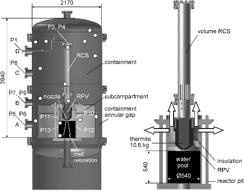
The fuel is simulated by a thermite iron–alumina melt at a temperature of about 2400 K, obtained from a thermite reaction initiated directly inside the RPV vessel a few seconds before its delivery to the pit through a nozzle. The delivery occurs as a result of the melting of a brass fuse inside the nozzle. Before the delivery, the vessel pressure can be adjusted through a steam accumulator placed outside of the containment vessel and connected to the RCS vessel at level D. The nozzle diameter was set to 0.030 m corresponding roughly to 0.30 m at reactor scale.
The primary circuit is simplified and simulated with one single vessel. Inside this vessel, two zones represent the RPV and the RCS, linked with a system of small pipes to adjust the pressure loss (found to have no real impact in fact). The initial gas composition in the DISCO containment can be modeled by different air, steam and hydrogen mixtures. To limit the hydrogen combustion effects, no hydrogen was initially present in the containment in this test, the containment atmosphere contained only air and steam. The height of the reactor pit was 0.984 m and the diameter 0.54 m. The water level in the reactor pit was set to ∼0.54 m, just below the nozzle outlet. The water temperature at the beginning of the test was set to 85 °C to keep the subcooling in the range close to the expected one during the accident. The main test parameters are given in
Table 1. Main parameters of the test.
The containment vessel was closed at atmospheric pressure and room temperature. For a period of up to 8 hours, steam was filled into the containment vessel additional to the air atmosphere until the pressure reached 0.2 MPa and the gas temperature was close to 100 °C, while the condensate was frequently drained. Two fans were running until the blow-down was started, to ensure a well-mixed atmosphere. The accumulator was pressurized with steam to 0.9 MPa.
The experiment was started by igniting the thermite electro-chemically at the upper surface of the compacted thermite powder. The ignition is achieved by a thin wire made of an inner core of aluminum and an outer core of palladium/ruthenium. By electric resistance heating, the temperature is raised to 650 °C, at which an alloying reaction between the metals starts resulting in a rise in the temperature to 2800 °C. The trade name is Pyrofuse. When the pressure rise in the RPV/RCS vessel indicates that the thermite reaction has started, the valve in the line connected to the steam accumulator is opened and steam enters the RCS vessel, which is preheated to the saturation temperature of the planned burst pressure. The pressure balance between both vessels is reached quickly and the valve is automatically closed again. About 3–6 s after ignition, the brass plug at the bottom of the RPV vessel is melted by the 2400 K hot iron–alumina mixture. That initiates the melt ejection. The melt is driven out of the breach by the steam and is dispersed into the cavity and beyond.
3. Main experimental results
The DISCO test results include pressures (15 pressure transducers, 1.7 MPa, 3.5 MPa and 30 MPa maximum range) and temperatures (25 thermocouples, with a maximum range of 1400 °C) in the RPV, the cavity, the reactor compartments and the containment vessel, post-test melt fractions in all locations with size distribution of the debris. The total debris mass dispersed into the DISCO vessel and the debris mass in specific locations are determined by a post-test debris recovery procedure. Loose particles are collected and weighed separately for each location. The total weight of crusts is determined by pre- and post-test weighing of all parts of the test facility, or if not possible, by removing the crusts from the parts and weighing of them. A post-test sieve analysis of the debris recovered from different locations is performed with a standard set of 17 sieves (10 mm to 40 μm). Except for small pieces, crusts are generally not included in the sieve analysis. Therefore, the information on the droplet size of the melt that has impacted on walls and formed a crust is not available. This has to be taken into account when the results of the sieve analysis are evaluated.
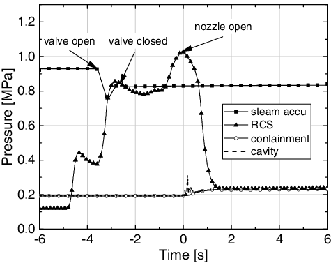
The pressure histories in all vessels and compartments are shown in . The steam pressure in the accumulator is initially at 0.92 MPa. The initial pressure in the RCS/RPV vessel is 0.1 MPa by nitrogen. After the start of the thermite burn, the pressure rises only by heat-up of the nitrogen gas within the vessel and reaches a first peak at ∼0.4 MPa. The thermite reaction does not generate substantial gas. When the valve of the accumulator opens and steam enters the RCS vessel, the pressure in the RCS/RPV rises once more until the valve is closed to a second peak at 0.82 MPa. The continued heating by the thermite reaction leads to a pressure of 1.02 MPa at the time when the brass plug at the nozzle melts and the melt discharge occurs. Time 0 is set to the onset of the melt discharge.
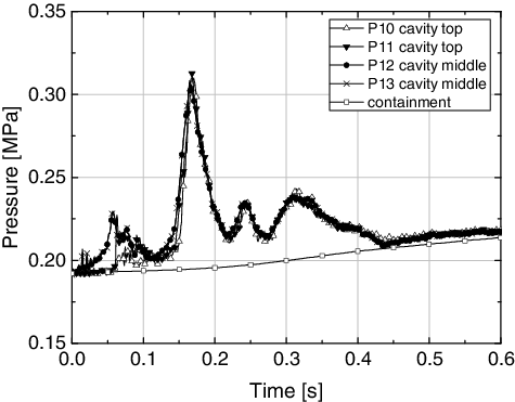
A series of some small pressure peaks were registered in the cavity during the first 0.5 s after the melt discharge which are shown in detail in . Initially the pressure is different inside the liquid pool and above, but it becomes homogeneous after 0.1 s. The maximum peak is about 0.1 MPa above the initial pressure at t = 0.17 s. However, this pressure increase cannot be attributed to a steam explosion, which would result in much higher pressure spikes of several MPa and shorter duration. It is an effect of rapid boiling and quenching of hot melt droplets. The pressure balance with the containment pressure occurs 0.3 s later.
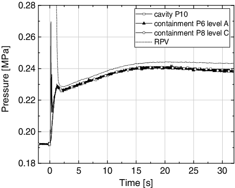
shows the pressure development in the containment vessel, the cavity and the RPV during 32 s. The initial pressure in the containment vessel was 0.192 MPa. The final pressure reached in the cavity and in the containment amounted to 0.24 MPa. The pressure increase in the containment is about 0.04 MPa during the first second of test, up to equilibrium with the pressure in the RPV. The small offset between the two pressures is due to a calibration error and was not corrected here. After the containment pressure reaches a first peak near 0.23 MPa, it drops again during 1 s and thereafter slowly increases for approximately 14 s to reach a plateau at 0.24 MPa. Only then it decreases slowly. Such behavior was not observed in the previous DISCO tests addressing DCH issues in a dry reactor cavity [Citation1–3]. In experiments with dry cavity, the containment pressure decreased in all tests continuously after reaching the first peak due to the cooling of the heated gas (, from the test DISCO-H01, described in [Citation1] and in more detail in [Citation3]). With a wet cavity, the vaporization of the water leads to a further pressure increase at a lower temperature level compared to the higher gas temperatures in dry cavities and containments. The subsequent temperature plots will elucidate this assumption.
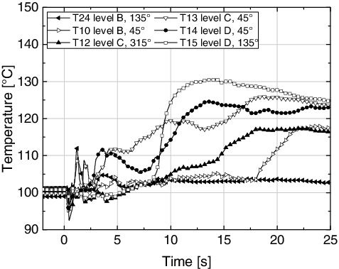
shows the temperature signals taken in the containment vessel at different locations. Generally, the increase of the temperature in the containment and in the cavity is slower than the corresponding pressure increase. The second slow pressure rise after 2 s is most probably due to the evaporation of water ejected from the cavity together with hot debris. The temperature level is much lower than in experiments with dry cavities (, from the test DISCO-H01, described in [Citation1] and in more detail in [Citation3]), where heat is transferred from the hot debris to the containment atmosphere; additionally more hydrogen is produced and burned consecutively. After ∼12 s, the temperature reaches a maximum value of 130 °C (403 K) while the temperature in the lower part of the containment is at about 105 °C (377 K). The temperatures then slowly decrease due to heat losses and slow equilibration of temperature in the various parts of the vessel.
Figure 7. Long-term temperature in the containment with dry cavity (DISCO-H01, [Citation1,Citation3]).
![Figure 7. Long-term temperature in the containment with dry cavity (DISCO-H01, [Citation1,Citation3]).](/cms/asset/ae143fa7-685c-47e1-9dcf-27a3946122e2/tnst_a_1127785_f0007_b.gif)
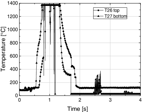
The high temperature observed in the cavity () after 0.5 s indicates the effect of the hot melt together with the water ejection from the cavity. The water inside the cavity was almost totally ejected. The post-test analysis shows that only 5 kg out of the initial 125 kg of water remained in the cavity.
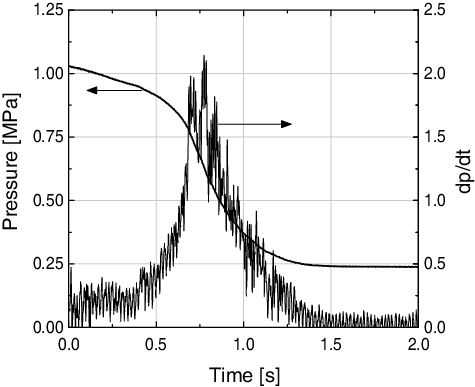
Three distinct stages can be recognized in the curves of the RPV pressure: first, a slow decrease; second, a steep drop up to a maximum slope; and third, a slowing down of the pressure drop (). These stages can be detected better if the pressure gradient dp/dt is plotted versus time. An almost constant low gradient exists for 0.4 s at the beginning of the blow-down, which can be interpreted as a liquid single-phase or nearly single-phase jet. The second stage is a two-phase flow, starting slowly and reaching a peak volume flow at approximately 0.8 s when the single-phase steam flow begins. At this point of time the pressure ratio of the vessel pressure and cavity pressure is still supercritical, and choked flow prevails. The pressure peaks in the cavity accompanied by small temperature peaks up to 0.5 s arise during the melt ejection phase ( and ) while the high temperature signals () show up later. These high signals can only be generated by hot melt coming close to the thermocouples without the presence of water. Thus, some water is ejected first by rapid vaporization but the main part is ejected during the second phase by the blow-down of the gas initially present in the RPV/RCS.
After the test, the debris in the DISCO vessel was recovered from all cavity surfaces, all surfaces in the subcompartment, on the cover of the subcompartment, on the vessel wall, dome surface and structures inside the containment. The amount of debris recovered was larger than the initial thermite charge, which is due to the partial melting of the steel liner inside the RPV vessel ().
Table 2. Analysis of the debris recovered post-test.
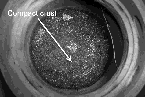
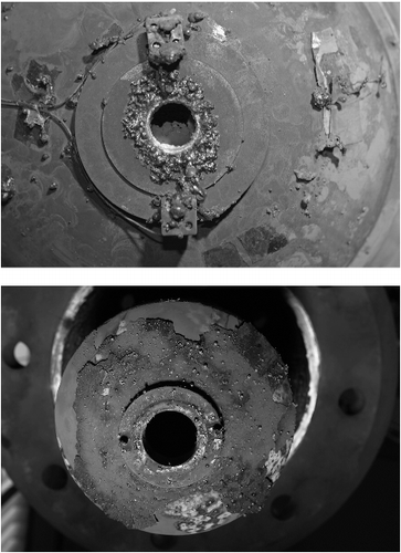
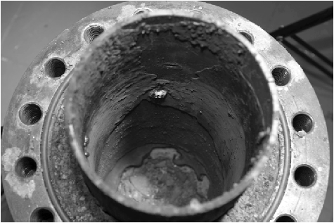
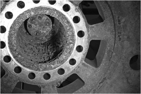
shows a picture of the cavity floor after the test. About 60% of the melt was found on the cavity floor as a compact crust. The surface of the crust is rough and its thickness is not uniform. The depression in the middle indicates that the jet impacted on the cavity floor. The melt slipped upwards along the wall only for few centimeters and the cavity walls further up are quite clean. This is different from dry DCH tests [Citation1–3], where the remaining melt was in the form of smooth layers, indicating a late solidification. In the present test, partial solidification of the melt happened at impact on the floor and led to high retention of melt in the cavity. Similarly, only little melt stayed stuck to the outside of the RPV, compared to dry DCH tests (). The melt was found in the form of local accumulation of droplets close to the nozzle and the rest of the RPV was almost free of debris. This would indicate that melt was transported out of the pit with the water.
Approximately 6% of the debris was found inside the RPV, similar to all DCH tests (). However, 10% of debris was found in the RCS part, which means a reverse upward flow of melt droplets from the RPV to the RCS (). Since the pressure peaks in the cavity were lower than the pressure in the RPV at the time of their occurrence, it is unlikely that this happened during blow-down of the melt. The most probable process leading to this result is a violent reaction during the thermite burning. This matter remains to be further investigated.
Part of the melt ejected inside the containment dome was found stuck on the upper part of the dome in the form of very small particles. Approximately 9% of the melt was transported to the subcompartment as small particles. It is likely that this part of the melt was rapidly solidified.
The results of the debris recovery and sieve analysis are presented in . The distribution of mass after the post-treatment is the following:
remained in cavity: ∼60% mainly as compact crusts;
transported to subcompartment ∼9%;
transported to containment ∼15%;
ejected into RCS: ∼10%; and
remained in RPV: ∼6%.
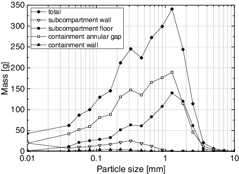
The fragmented debris was sieved and the mass partition of particles is shown in . The results of the analysis concerning the different averaged diameters are the following:
Sauter mean diameter = 160 μm;
mass median diameter = 0.4 mm; and
mass mean diameter = 0.7 mm.
The size of the particles is very small compared to the classical data from FCI experiments under gravity pour, where the mean diameters are of the order of some few millimeters [Citation7], despite a smaller melt density of the simulant melt compared to the corium melt. This might be explained by the high velocity of the discharged melt jet (a rough estimate of the ejection velocity amounts to about 14 m/s). Possibly some larger particles were still molten when impacting floors and walls, this means the debris size is representative only for the solidified debris before they reach a wall.
4. Conclusions
In the frame of the LACOMECO project of the 7th European Framework Program, a test was performed in the DISCO facility at KIT in order to analyze the phenomena during an ex-vessel FCI. The test is focused on the premixing phase of the FCI with no trigger used for explosion phase. The reactor cavity model was close to a French 900 MWe reactor configuration at a scale of 1:10. The main objectives of the test were to evaluate the dispersion of water and melt out of the pit, characterize the debris and provide the pressurization of the reactor compartments for scenarios, where the melt is ejected from the RPV under pressure.
The corium was modeled by an iron–alumina melt at the temperature of 2400 K that was driven by steam, and a prototypic atmosphere in the containment was applied. For comparison and modeling purposes, the test was conducted without pre-existing hydrogen and the pressure in containment was set to 1 bar of air and 1 bar of steam. To be conservative, the test was performed with a central hole at the lower bottom head. The water level in the pit was about 0.54 m, just below the nozzle, at a temperature of 85 °C.
The containment pressure increased by 0.04 MPa and reached about 0.24 MPa. The pressure in the cavity was characterized by several small peaks. The highest peak (0.1 MPa of pressurization, at 0.017 s) cannot be ascribed to a steam explosion. The water inside the cavity (initial 125 kg) has been totally ejected.
Concerning the debris, of the initial melt mass (10.62 kg thermite melt plus 1.0 kg molten steel) 16% remained in the RCS/RPV vessel, 60% remained in the cavity mainly as compact crusts. The fraction of melt transported to subcompartment and containment were about 9% and 15%, respectively. The size distribution supplied by sieved analysis indicated a tendency to small particles with a Sauter mean diameter of 160 µm, a mass median diameter of 0.4 mm and a mass mean diameter of 0.7 mm.
The results of the experiment shall be compared with calculations of the MC3D code.
Acknowledgements
The authors gratefully acknowledge funding by Euratom to support the work within the LACOMECO project [grant agreement number 249682].
Disclosure statement
No potential conflict of interest was reported by the authors.
References
- Meyer L, Albrecht G, Caroli C, et al. Direct containment heating integral effects tests in geometries of European nuclear power plants. J Nucl Eng Des. 2009;239:2070–2084.
- Meignen R, Plassart D, Caroli C, et al. Direct containment heating at low primary pressure: experimental investigation and multi-dimensional modeling. Paper presented at: NURETH-11: 11th International Topical Meeting on Nuclear Reactor Thermal Hydraulics; 2005 Oct 2–6; Avignon, France.
- Meyer L, Albrecht G, Kirstahler M, et al. Melt dispersion and direct containment heating (DCH) experiments in the DISCO test facility. Karlsruhe (Germany): Forschungszentrum Karlsruhe; 2004. (no. 6988).
- Miassoedov A, Kuznetsov M, Steinbrück M, et al. Experiments of the LACOMECO project at KIT. Paper presented at: ERMSAR-2012: 5th European Review Meeting on Severe Accident Research; 2012 Mar 21–23; Cologne, Germany.
- Huhtiniemi I, Magallon D, Hohmann H. Results of recent KROTOS FCI tests: alumina versus corium melts. J Nucl Eng Des. 1999;189:379–389.
- OECD/SERENA Project Report. Summary and conclusions. Paris (France): OECD; 2015. (no. NEA/CSNI/R(2014)15). Available from: https://www.oecd-nea.org/nsd/docs/2014/csni-r2014-15.pdf
- Meignen R, Raverdy B, Buck M, et al. Status of steam explosion understanding and modelling. Ann Nucl Energy. 2014;74:125–133.
- Meignen R, Picchi S, Lamome J, et al. The challenge of modeling fuel–coolant interaction: part I – premixing. J Nucl Eng Des. 2014;280:511–527.
- Meignen R, Raverdy B, Picchi S, et al. The challenge of modeling fuel–coolant interaction: part II – explosion. J Nucl Eng Des. 2014;280:528–541.
- Meignen R, Tanguy J. On the analysis and evaluation of direct containment heating with the multidimensional multiphase flow code MC3D. Sci Technol Nucl Install. 2009;2010:1–13. Article ID 289792.
- Albiol T, Van Dorsselaere JP, Chaumont B, et al. SARNET: severe accident research network of excellence. Prog Nucl Energy. 2010;52:2–10.

![Figure 5. Long-term pressure in the containment with dry cavity (DISCO-H01, [Citation1,Citation3]).](/cms/asset/0e522931-849e-46b6-804b-5edc78a2d03c/tnst_a_1127785_f0005_b.gif)
