
ABSTRACT
Various types of nanometric defects such as voids and helium (He) bubbles produced by high-energy neutron irradiations are known to degrade the mechanical properties of irradiated materials. In this study, we have evaluated the obstacle strength of He bubbles to the mobility of an edge dislocation in α-iron for 2 and 4 nm bubbles with He-to-vacancy (He/V) ratios ranging from 0 to 1 at 300 and 500 K, by molecular dynamics simulation. Results showed that as the He/V ratio increases, the obstacle strength needed for the release of a dislocation from the bubble becomes stronger up to a moderate He/V ratio (0.6 and 0.4 for 2 and 4 nm bubbles, respectively, at both temperatures), and a further increase in the He/V ratio leads to weakening of the obstacle strength. For He/V = 1, the obstacle strengths are 10–30% weaker than those at moderate He/V ratios depending on the bubble size and temperature. The extent of obstacle strength was found to be correlated with the dilation caused by He bubbles depending on the bubble size, He/V ratio, and temperature.
1. Introduction
Various types of crystal defects are known to act as obstacles for dislocation motion, thereby affecting their mechanical properties. These obstacles include voids [Citation1–3], helium (He) bubbles [Citation4–7], nano-bubbles with dissociated polymer gases [Citation8,Citation9], dislocation loops [Citation10–12], stacking fault tetrahedron [Citation13–17], and precipitates [Citation1,Citation18–21]. In general, voids have a rather simple symmetric morphology and are mainly formed when the structural materials are irradiated with high-energy particles over a wide temperature range. Therefore, there have been significant efforts in terms of computational and experimental studies from this perspective.
Under significantly high-energy neutron irradiations, such as those in fusion reactors, He atoms can be produced by transmutation reactions. Because of the low solubility of He atoms in α-iron (Fe), they have a high tendency to coalesce in the form of nanometric bubbles [Citation22], thereby playing an important role in the microstructural evolution. Thus far, several studies have discussed the mechanism underlying the interaction between a dislocation and He bubble in α-iron by molecular dynamics (MD) simulation studies [Citation4–7]. Hafez Haghighat et al. [Citation5,Citation6] studied the effect of the bubble size coupled with its He content on the interaction of an edge dislocation with highly pressurized He bubbles at various temperatures. According to their study, an increase in the bubble size increases the number of dislocation segments punched out from the bubble at a constant He density, leading to a higher influence on bubble strengthening at larger bubble sizes. However, the investigated He-to-vacancy (He/V) ratio was up to 6, which might be considerably high when considering the detailed evaluations of thermally stable He/V ratios in relatively small bubbles [Citation23–26]. Although the latter results were obtained by evaluating the dissociation energies of He bubbles on the basis of static calculations, it indicates that the thermally stable He bubbles are achieved at He/V ratios ranging from 0.5 to 2, depending on the interatomic potentials used. Furthermore, regarding the finite temperature effect, Stewart et al. [Citation27] simulated He bubbles of diameter up to 6 nm with different He/V ratios over a wide temperature range. By defining an equilibrium condition for He bubbles as the point at which the dilation becomes zero, the study revealed that the equilibrium He/V ratios range from 0.35 to 0.55, depending on bubble size and temperature. Recently, Stoller and Osetsky [Citation28] revealed that the equilibrium He/V obtained for bubbles 2–5 nm in diameter is about 0.4–0.7 at room temperature and weakly decreases with increasing temperature. The equilibrium He/V ratios evaluated by the MD studies [Citation27,Citation28] are consistent with 0.25–0.85 determined experimentally using electron energy loss spectroscopy for bubbles from 2 to 5 nm in ferritic-martensitic steels [Citation29].
Based on the computationally and experimentally reasonable range of He/V ratio, Osetsky and Stoller [Citation7] investigated the interactions between a moving edge dislocation and He bubbles with relatively low He contents using a large-scale MD simulation at 300 K. They found that the obstacle strength of He bubbles depends weakly on He/V ratio within the range of 0–0.8, and decreases at higher He/V ratios. They also pointed out that the dislocation climb due to the interaction with He bubbles depends on the He/V ratio, and the maximum obstacle strength is usually correlated with the minimum climb. However, the associated interaction mechanism has not been clarified yet.
In this study, we perform MD simulations on the interactions of an edge dislocation with nanometric He bubbles of various sizes, He/V ratios, and temperatures. The behavior of dislocation-bubble interactions is widely investigated, and the dependence of the obstacle strength of He bubbles on He/V ratio is analyzed in terms of the dilation caused by He bubbles to clarify a possible interaction mechanism.
2. Simulation method
The dislocation motion in the presence of He bubbles was investigated by MD simulation. We have reported the details of the code developed for implementing this simulation in previous studies [Citation30,Citation31]. In this study, we investigated the effects of bubble size, He content inside a bubble, and temperature on yield behavior. To simulate the He/V ratio, we considered spherical He bubbles of diameter (D) 2 and 4 nm for He/V ratio = 0, 0.2, 0.4, 0.6, and 1 at 300 and 500 K.
A simulation box consists of an edge dislocation in the ⟨112⟩ direction and a He bubble on the dislocation slip plane, {110}. Periodic boundary conditions were applied along the dislocation line direction, ⟨112⟩, and dislocation glide direction, ⟨111⟩. The dimensions of the box along the ⟨110⟩, ⟨112⟩, and ⟨111⟩ directions, were 20, 41, and 25 nm, respectively. This set of dimensions is similar one as applied in [Citation7] for relatively small He bubbles. The system had a total of 1,746,000 atoms. The {110} plane located on the bottom surface was fixed to anchor the specimen, and only the movement in the direction of ⟨111⟩ of the {110} plane on the top surface was allowed to control the deformation of the sample during the simulation. To model the deformation mode, the shear stress resulting from an imposed stain rate was calculated at each time step from the internal force of atoms in the upper region of the sample. The corresponding maximum shear stresses were achieved just before the dislocation was released from a bubble. The time step was taken to be 0.1 fs. Prior to straining, an annealing condition was applied over 2 ps to stabilize the temperature of the simulation box. The applied strain rate was 1 × 10⁷ s−1, which value has been demonstrated to have a negligible effect on the stress-strain variations for the interactions of an edge dislocation with voids and precipitates [Citation1,Citation2,Citation21]. For the case of He bubbles, we examined the strain rate effect on the stress-strain variations by applying 1 × 10⁷ and 5 × 10⁶ s−1 (as applied in [Citation7]) for a few cases with He/V ratios at 300 K, and found that the relative errors in the maximum shear stresses were less than a few percent. To describe Fe–Fe, Fe–He, and He–He interactions, the empirical potentials developed by Ackland et al. [Citation32], Juslin and Nordlund [Citation33], and Beck [Citation34], respectively, were employed. It has been shown that this combination of potentials gives similar results to density functional theory calculations [Citation24] for small cluster sizes, and in particular allows one to reproduce the values of binding energies of vacancies and interstitial helium atoms to vacancy-helium clusters as a function of the He/V ratio [Citation25].
3. Results and discussions
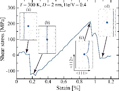
shows the shear stress as a function of applied strain in a crystal model containing an edge dislocation gliding through a He bubble having a diameter of 2 nm and He/V = 0.4 at 300 K as a representative case of the temporal behavior of pinning-depinning processes investigated in this study. Snapshots of the atomic configurations at some characteristic stages during its interaction are also presented in this figure. The atomic configurations of the He bubbles and the dislocation core were extracted only for atoms with potential energies above −4.06 eV. Under the shear stress, the edge dislocation glides towards the ⟨111⟩ direction ((a)). The gliding dislocation is then attracted by and pulled into the bubble when the dislocation reaches the vicinity of the bubble. Consequently, the shear stress decreases ((b)). Subsequently, it bowed out under the action of increasing stress until it reached a maximum stress ((c)), and finally escaped from the bubble, causing a large drop in the stress ((d)). The maximum shear stress is then defined as the critical shear stress, just before the release from He bubbles.
Figure 1. Plot of shear stress as a function of strain in a crystal containing an edge dislocation gliding through a He bubble with bubble size of 2 nm and He/V = 0.4 at 300 K. Successive snapshots of the extracted atomic configurations in the {110} slip plane are inserted: (a) dislocation gliding in a matrix, (b) trapping of the dislocation by a He bubble, (c) just before the depinning, (d) after the depinning.
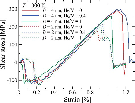
shows the stress-strain relation for different bubble sizes and He/V ratios at 300 K. Although the maximum shear stresses for bubbles of diameter 4 nm are larger than those for bubbles of diameter 2 nm, the dependence of the maximum shear stresses on the He/V ratio shows a non-monotonic behavior: He bubble with a moderate He/V ratio (= 0.4) leads to a slightly higher maximum shear stress when compared with a pure void (He/V = 0), and a pressurized bubble (He/V = 1) causes a relatively lower maximum shear stress than the others.
Figure 2. Plot of shear stress as a function of strain in a crystal containing an edge dislocation gliding through He bubbles with different bubble sizes and He/V ratios at 300 K.
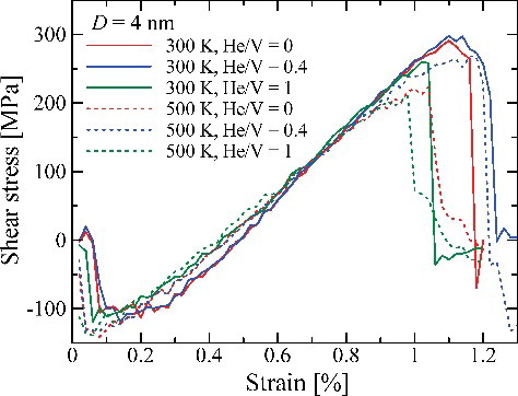
illustrates the stress-strain curves corresponding to He bubbles of diameter 4 nm as a function of different He/V ratios and temperatures. With increasing in temperature, the maximum shear stresses tend to decrease, irrespective of the He/V ratio. For pure voids (He/V = 0), this could be attributed to an increase in the mobility of screw segments formed at the bubbles when they detach from the bubbles, easing their annihilation, and thus reducing the maximum shear stress as demonstrated in [Citation1,Citation2]. For He bubbles, although the overall detaching process undergoes in a similar way as for pure voids, the dilation caused by He bubbles depending on the temperature also affects the obstacle strength as discussed later.
Figure 3. Plot of shear stress as a function of strain in a crystal containing an edge dislocation gliding through 4 nm bubbles with different He/V ratios and temperatures.
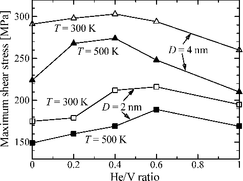
shows the maximum shear stresses evaluated for He bubbles as a function of He/V ratios with different bubble sizes and temperatures. Within the presented values of He/V ratio, the maximum shear stresses are observed to be higher for a larger He bubble (D = 4 nm) and lower temperature (T = 300 K). At 300 K, although the overall tendency of the dependences of the maximum shear stress on He/V ratio is similar to those obtained by Osetsky and Stoller (see in [Citation7]) using different Fe–He [Citation35,Citation36] and He–He [Citation36] interatomic potentials, the maximum shear stresses evaluated in this study are about 50 and 100 MPa larger than those obtained in [Citation7] for bubbles of 2 and 4 nm, respectively, for a wide range of He/V ratio. Also, while they found that the maximum shear stress depends weakly on He/V ratio within the range of 0–0.8, and decreases at higher He/V ratios [Citation7], the present result shows that the maximum shear stresses are non-monotonic functions of the He/V ratio at both temperatures (300 and 500 K): with increasing in the He/V ratio, the obstacle strengths for both bubble sizes (2 and 4 nm) become stronger, up to moderate He/V ratio, and the further increase in the He/V ratio weakens the obstacle strength.
Figure 4. Maximum shear stresses as a function of He/V ratio with different bubble sizes and temperatures.
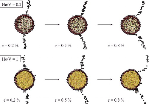
By using the visualization software AtomEye [Citation37], shows successive snapshots of dislocation lines in the {110} slip plane through the center of 4 nm He bubbles with different He/V ratios at 300 K. It can be seen that the He atoms stand off a relatively large distance from the surface Fe atoms for He/V = 0.2 as reported by Stewart et al. [Citation27]. For He/V = 1, on the other hand, the gap becomes narrower, indicating that the He pressure becomes higher with increasing He/V ratio. Indeed, the He pressure is a monotonically increasing function of He/V ratio [Citation38], and the estimated He pressure for He/V = 1 was about 25 times higher than that for He/V = 0.2 in this study. According to this consideration, the He pressure in the bubbles does not have a critical impact on the determination of the maximum shear stresses, because the maximum shear stresses are non-monotonic functions of the He/V ratio as shown in . Note that the dislocation core does not propagate into He bubbles as the case for voids [Citation1–3] probably because the intersecting dislocation loses its line segment by the gap (i.e., vacant sites) present inside the He bubbles at least in the low He density range investigated in this study. This is an energetically favorable state because the dislocation line energy inside the bubble will become zero. This interaction mechanism is contrast to that for small coherent copper precipitates (D ≤ 2 nm), where a simple shear does not cause any additional changes in precipitate or dislocation structures [Citation1,Citation21].
Figure 5. Successive snapshots of dislocation lines and He bubbles in the {110} slip plane through the center of 4 nm He bubbles at 300 K. The dark-colored spheres represent the Fe atoms that make up the dislocation core and surface of the bubbles, while the light-colored spheres stand for the He atoms in the bubbles. He/V ratios (= 0.2 and 1) and the corresponding strains, ε, are indicated in each case.
shows the shapes of a dislocation along the [111] projection after it is detached from a He bubble with different He/V ratios for 2 and 4 nm bubbles at 300 K. For pure voids (He/V = 0), the dislocation climbs up by absorbing some vacancies from the voids while breaking away, as reported in previous studies [Citation1–3,Citation39–41]. According to these studies, the amount of climb up depends on the void size, D, irrespective of interatomic potentials. For 2 nm bubbles as shown in (a), although the dependence of the amount of climb up of the dislocation line on the He/V ratio, the number of vacancies absorbed by the dislocation, is relatively weak, the amount of climb up seems to decrease with increasing the He/V ratio. For 4 nm bubbles as shown in (b), the amount of climb up does not change largely, irrespective of He/V ratio, except for He/V = 1. The dislocation line shape for 4 nm bubble with He/V = 1 indicates that the dislocation line becomes to absorb more atoms instead of vacancies from the bubble and climbs down in contrast to the cases for bubbles with lower He/V ratios. This behavior is consistent to the MD results obtained by Osetsky and Stoller [Citation7].
Figure 6. Dislocation lines viewed along the [111] projection perpendicular to the Burgers vector after detaching from (a) 2 nm and (b) 4 nm He bubbles of different He/V ratios at 300 K.
![Figure 6. Dislocation lines viewed along the [111] projection perpendicular to the Burgers vector after detaching from (a) 2 nm and (b) 4 nm He bubbles of different He/V ratios at 300 K.](/cms/asset/8aa1cac9-da76-4a61-9df4-45187e1ca1ae/tnst_a_1133332_f0006_oc.jpg)
To investigate a possible mechanism of the non-monotonic dependence of the maximum shear stress on the He/V ratio as seen in , we estimated the dilation caused by a He bubble as functions of bubble size and temperature. The dilation is represented by the lattice distortion as the change in the bubble radius relative to the one in a perfect lattice. As applied by Stewart et al. [Citation27], the equilibrium He/V ratio for each temperature was defined as the point at which the dilation becomes zero. shows the dilations of 2 and 4 nm He bubbles as a function of He/V ratio at different temperatures. While the temperature variation of the dilations is relatively small, irrespective of the He/V ratio for each bubble size, the dilation for a 4 nm bubble with He/V = 1 is notably larger than the other cases. The equilibrium He/V ratios may be around 0.6 and 0.3–0.6 for 2 and 4 nm bubbles, respectively, at both temperatures, but the exact values cannot be determined due to the relatively large standard errors. Although the estimated equilibrium He/V ratios for both bubble sizes are generally higher by about 0.1 than those systematically evaluated by Stewart et al. [Citation27], in which they used different Fe–He [Citation35,Citation42,Citation43] and He–He [Citation44] potentials, the overall variation trend of the dilations regarding the bubble size and temperature is consistent, irrespective of the interatomic potentials used.
Figure 7. Dilations, ΔR, of 2 and 4 nm He bubbles as a function of He/V ratio at different temperatures. The dilations are normalized by a lattice constant, a0. The error bars represent standard errors estimated for each calculation.
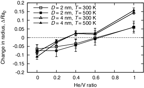
Comparing the estimated equilibrium He/V ratios with the variation of the maximum shear stresses as a function of the He/V ratio as shown in , the lower maximum shear stress seems to be correlated with the larger deviation from the equilibrium He/V ratio depending on the bubble size and temperature. This may be attributed to the relaxation of the excess energy originating from the dilation of the bubble by the assist of the intersecting dislocation. It is assumed that for He/V ratio smaller than the equilibrium value, the bubble would be stabilized if the number of vacancies in the bubble decreases, resulting in an increase in the He/V ratio. This situation can be realized when the intersecting dislocation absorbs some vacancies from the bubble. On the other hand, for larger He/V ratio than the equilibrium value, the bubble would be stabilized upon the separation of the dislocation from the bubble by absorbing some atoms that constitute the bubble surface. This, in turn, leads to a decrease in the He/V ratio toward the equilibrium condition. Note that although the overall tendency of the dependences of the maximum shear stress on He/V ratio for 2 and 4 nm bubbles at 300 K evaluated by Osetsky and Stoller (see in [Citation7]) is similar to that () obtained in this study, the correlation between the extent of the reported maximum shear stress and the presently estimated dilation caused by a He bubble () seems to be low. This is probably attributed to the different Fe–He and He–He interatomic potentials used in these studies because the other numerical conditions are similar. In this study, it enabled us to make a direct comparison of the relation between the maximum shear stress and the dilation caused by a He bubble as a function of He/V ratio with different bubble sizes and temperatures by applying the same potential set for the evaluations of these two physical quantities. It should be pointed out that the interaction of an edge dislocation with a He-filled bubble is expected to involve a more complicated atomistic process than those with a void and a coherent precipitate so the clarification of a quantitative relation between the maximum shear stress and the dilation caused by a He bubble can be difficult, and may require additional simulations at lower strain rates or temperatures to reduce inaccuracy in evaluating these values.
As shown in , these interaction processes may be identified visually as the configurations of the dislocation line upon intersecting the He bubbles. The amount of climb up of the dislocation line seems to be relatively large for pure voids (He/V = 0) of both sizes, while a significant amount of climb down can be recognized for 4 nm bubble with He/V = 1. These cases correspond to the large dilations caused by He bubbles, and the resultant maximum shear stresses become lower than those for bubbles with moderate He/V ratios as shown in . Note that the obstacle strength of 4 nm bubble with He/V = 1 is even weaker than the corresponding void (He/V = 0) for each temperature investigated. For moderate He/V ratios, on the other hand, since the dependence of both the amounts of climb up and the dilations caused by He bubbles on the He/V ratio is rather weak, the correlation with the dependence of the maximum shear stress is not clear. Toward verifying the interaction mechanism provided in this study, it is necessary to reduce the uncertainty in the evaluations of the maximum shear stress and the dilation caused by He bubbles by performing these calculations at lower temperature and strain rate, and the study of which is currently in progress.
4. Conclusions
This study investigated the effect of the dilation caused by He bubbles on edge dislocation motion in α-iron for 2 and 4 nm bubbles with He-to-vacancy (He/V) ratios ranging from 0 to 1 at 300 and 500 K by using MD simulation. It was found that pure voids (He/V = 0) and pressurized bubbles (He/V = 1) lead to lower maximum shear stresses when compared with those for moderate He/V ratios (0.6 and 0.3–0.6 for 2 and 4 nm bubbles, respectively, at both temperatures). For He/V = 1, the maximum shear stresses were 10–30% lower than those at moderate He/V ratios depending on the bubble size and temperature. The lower maximum shear stress were found to be achieved when the He bubbles are largely deviated from the equilibrium He/V ratio, as defined by a zero total dilation depending on the bubble size, He/V ratio, and temperature. For He/V ratios smaller and larger than the equilibrium value, the bubbles would be stabilized by the decrease and increase in the number of vacancies inside the bubbles, respectively, as the resultant He/V ratios shift toward the equilibrium value. The intersecting dislocation would play a role in assisting the reduction of the bubble dilation originated from lattice distortions by absorbing either vacancies or atoms from the bubbles. Further clarification of the underlying mechanism will provide a comprehensive and fundamental understanding of the strengthening mechanisms induced by various bubbles containing other gas and liquid elements.
Acknowledgments
This work was supported by Japan Society for the Promotion of Science (JSPS) Grant-in-Aid for Challenging Exploratory Research [number 24656425].
Disclosure statement
No potential conflict of interest was reported by the authors.
References
- Osetsky YN, Bacon DJ. Void and precipitate strengthening in α-iron: what can we learn from atomic-level modelling? J Nucl Mater. 2003;323:268–280.
- Osetsky YN, Bacon DJ. Atomic-scale mechanisms of void hardening in bcc and fcc metals. Phil Mag. 2010;90:945–961.
- Hafez Haghighat SM, Fikar J, Schäublin R. Effect of interatomic potential on the behavior of dislocation-defect interaction simulation in α-Fe. J Nucl Mater. 2008;382:147–153.
- Schäublin R, Chiu YL. Effect of helium on irradiation-induced hardening of iron: a simulation point of view. J Nucl Mater. 2007;362:152–160.
- Hafez Haghighat SM, Lucas G, Schäublin R. Atomistic simulation of He bubble in Fe as obstacle to dislocation. Mater Sci Eng. 2009;3:012013.
- Hafez Haghighat SM, Schäublin R. Influence of the stress field due to pressurized nanometric He bubbles on the mobility of an edge dislocation in iron. Phil Mag. 2010;90:1075–1100.
- Osetsky YN, Stoller RE. Atomic-scale mechanisms of helium bubble hardening in iron. J Nucl Mater. 2015;465:448–454.
- Oono N, Kawano R, Shi S, et al. Synthesis of nano-bubble dispersion strengthened (N-BDS) metal by PMMA dissociated polymer gases. Mater Sci Eng A. 2013;582:245–247.
- Oono N, Kawano R, Shi S, et al. Irradiation effect of nano-bubble dispersion strengthened (N-BDS) alloy. J Nucl Mater. 2013;442:365–369.
- Diehl J. Vacancies and interstitials in metals. Amsterdam: North-Holland; 1969.
- Rodney D, Martin G. Dislocation pinning by glissile interstitial loops in a nickel crystal: a molecular-dynamics study. Phys Rev B. 2000;61:8714.
- Rodney D. Molecular dynamics simulation of screw dislocations interacting with interstitial frank loops in a model FCC crystal. Acta Mater. 2004;52:607–614.
- Dai Y, Victoria M. Defect structures in deformed f.c.c. metals. Acta Mater. 1997;45:3495–3501.
- Satoh Y, Yoshiie T, Mori H, et al. Formation of stacking-fault tetrahedra in aluminum irradiated with high-energy particles at low-temperatures. Phys Rev B. 2004;98:094108.
- Robach JS, Robertson IM, Lee HJ, et al. Dynamic observations and atomistic simulations of dislocation-defect interactions in rapidly quenched copper and gold. Acta Mater. 2006;54:1679–1690.
- Osetsky YN, Rodney D, Bacon DJ. Atomic-scale study of dislocation-stacking fault tetrahedron interactions. Part I: mechanisms. Phil Mag. 2006;86:2295–2313.
- Matsukawa Y, Briceno M, Robertson IM. Combining in situ transmission electron microscopy and molecular dynamics computer simulations to reveal the interaction mechanisms of dislocations with stacking-fault tetrahedron in nuclear materials. Microsc Res Tech. 2009;72:284–292.
- Odette GR. On the dominant mechanism of irradiation embrittlement of reactor pressure vessel steels. Scr Metall. 1983;17:1183–1188.
- Buswell JT, Bischler PJE, Fenton ST, et al. Microstructural developments in neutron-irradiated mild steel submerged-arc weld metal. J Nucl Mater. 1993;205:198–205.
- Nogiwa K, Nita N, Matsui H. Quantitative analysis of the dependence of hardening on copper precipitate diameter and density in Fe–Cu alloys. J Nucl Mater. 2007;367–370:392–398.
- Bacon DJ, Osetsky YN. Mechanisms of hardening due to copper precipitates in α-iron. Phil Mag. 2009;89:3333–3349.
- Rajainmäki H, Linderoth S, Hansen HE, et al. Nucleation and growth of helium bubbles in aluminum between 20 and 900 K. Phys Rev B. 1988;38:1087.
- Morishita K, Sugano R, Wirth BD, et al. Thermal stability of helium-vacancy clusters in iron. Nucl Instrum Methods Phys Res B. 2003;202:76–81.
- Fu CC, Willaime F. Ab initio study of helium in α-Fe: dissolution, migration, and clustering with vacancies. Phys Rev B. 2005;72:064117.
- Lucas G, Schäublin R. Stability of helium bubbles in alpha-iron: a molecular dynamics study. J Nucl Mater. 2009;386–388:360–362.
- Jourdan T, Crocombette JP. A variable-gap model for calculating free energies of helium bubbles in metals. J Nucl Mater. 2011;418:98–105.
- Stewart D, Osetsky YN, Stoller R. Atomistic studies of formation and diffusion of helium clusters and bubbles in BCC iron. J Nucl Mater. 2011;417:1110–1114.
- Stoller RE, Osetsky YN. An atomistic assessment of helium behavior in iron. J Nucl Mater. 2014;455:258–262.
- Fréchard S, Walls M, Kociak M, et al. Study by EELS of helium bubbles in a martensitic steel. J Nucl Mater. 2009;393:102–107.
- Tsuru T, Kaji Y, Matsunaka D, et al. Incipient plasticity of twin and stable/unstable grain boundaries during nanoindentation in copper. Phys Rev B. 2010;82:024101.
- Tsuru T, Kaji Y, Shibutani Y. Nanoscale contact plasticity of crystalline metal: experiment and analytical investigation via atomistic and discrete dislocation models. Acta Mater. 2010;58:3096–3102.
- Ackland GJ, Bacon DJ, Calder AF, et al. Computer simulation of point defect properties in dilute Fe–Cu alloy using a many-body interatomic potential. Phil Mag A. 1997;75:713–732.
- Juslin N, Nordlund K. Pair potential for Fe–He. J Nucl Mater. 2008;382:143–146.
- Beck DE. A new interatomic potential function for helium. Mol Phys. 1968;14:311–315.
- Seletskaia T, Osetsky YN, Stoller RE, et al. Devel-opment of a Fe–He interatomic potential based on electronic structure calculations. J Nucl Mater. 2007;361:52–61.
- Stoller RE, Golubov SI, Kamenski PJ, et al. Implementation of a new Fe–He three-body interatomic potential for molecular dynamics simulations. Phil Mag. 2010;90:923–934.
- Li J. AtomEye: an efficient atomistic configuration viewer. Modelling Simul Mater Sci Eng. 2003;11:173–177.
- Caro A, Hetherly J, Stukowski A, et al. Properties of helium bubbles in Fe and FeCr alloys. J Nucl Mater. 2011;418:261–268.
- Osetsky YN, Bacon DJ, Mohles V. Atomic modelling of strengthening mechanisms due to voids and copper precipitates in α-iron. Phil Mag. 2003;83:3623–3641.
- Schäublin R, Baluc N. Radiation damage in ferritic/martensitic steels for fusion reactors: a simulation point of view. Nucl Fusion. 2007;47:1690–1695.
- Terentyev D, Bacon DJ, Osetsky YN. Interaction of an edge dislocation with voids in α-iron modelled with different interatomic potentials. J Phys Condens Matter. 2008;20:445007.
- Seletskaia T, Osetsky YN, Stoller RE, et al. Calculation of helium defect clustering properties in iron using a multi-scale approach. J Nucl Mater. 2006;351:109–118.
- Stoller RE, Golubov SI, Kamenski PJ, et al. Implementation of a new Fe–He three-body interatomic potential for molecular dynamics simulations. Phil Mag. 2009;90:923–934.
- Aziz R, Janzen A, Moldover M. Ab Initio calculations for helium: a standard for transport property measurements. Phys Rev Lett. 1995;74:1586.