
 ?Mathematical formulae have been encoded as MathML and are displayed in this HTML version using MathJax in order to improve their display. Uncheck the box to turn MathJax off. This feature requires Javascript. Click on a formula to zoom.
ABSTRACT
This study is aimed to investigate the transient heat transfer process between the solid surface and the coolant (helium gas) in very high temperature reactor or intermediate heat exchanger. Transient heat transfer from a twisted plate with different length in helium gas was experimentally and theoretically studied. The heat generation rate was increased with an exponential function, Q = Q0exp(t/τ), where t is time and τ is period. Experiment was carried out at various periods ranged from 35 ms to 14 s. Platinum plates were twisted with the same helical pitch of 20 mm, and the effective lengths are 26.8, 67.8 and 106.4 mm (pitch numbers of 1, 3 and 5), respectively. It was clarified that the average heat transfer coefficient approaches quasi-steady-state value when the period τ is larger than about 1 s, and it becomes higher when τ is shorter than about 1 s. The heat transfer coefficient decreases with the increase of plate length. An empirical correlation for forced convection heat transfer for a twisted plate with various lengths was obtained based on the experimental data. Moreover, numerical simulation results were obtained for average surface temperature difference, heat flux and heat transfer coefficient of the twisted plates with different length and showed reasonable agreement with experimental data. Through the numerical simulation, distribution of heat transfer coefficient on heater surface, temperature distribution and velocity distribution were clarified.
1. Introduction
The Generation-IV systems, which comprise both the reactors and their associated fuel-cycle facilities, are intended to deliver significant advances compared with current advanced light water reactors in respect of economics, safety, environmental performance and proliferation resistance [Citation1]. The very high temperature reactor (VHTR) system is one of the promising candidates due to the features of inherent safety, high thermal efficiency and high temperature process heat potential. For such reactors, fuel elements are embedded in graphite core and cooled by helium gas.
While developing the VHTR system, some transient heat transfer process due to accidents e.g. power burst, rapid depressurization and withdraw of control rods are complicated and still under study. Hence, the understanding of transient heat transfer process on a solid surface caused by exponentially increasing heat input under wide experimental conditions such as gas velocity and geometric shape of the heater is important for the safety evaluation.
There are few experimental and analytical works on transient heat transfer process for helium gas flowing over a solid surface as far as authors know. Soliman and Johnson [Citation2] analytically obtained a temperature change in plate by taking into account the turbulent boundary around the plate. However, the solution of heat transfer coefficient for water is 50% higher than their experimental data. The simulations for transient heat transfer are also difficult due to the complex thermal hydraulic phenomena. Chen et al. [Citation3] tried transient simulation for helium cooled IFMIF (The International Fusion Materials Irradiation Facility) high flux test module by ANSYS CFX and Star-CD code and qualified the CFX k–ϵ model. However, the transient inner wall temperatures still have differences of over 10% by comparing to experimental results.
In addition, computer fluid dynamic (CFD) analysis is beginning to be applied in the thermal hydraulic analysis for a VHTR. Simplified models such as the equivalent cylinder model and the unit cell model have been widely used for the analyses and designs for prismatic reactors [Citation4]. Although a basic evaluation of heat transfer in the core can be acquired with economically reduced computational efforts, these simplified models are hard to take the interior heat transfer within a single fuel assembly and the gap flow between fuel assemblies into consideration. Thus, full three-dimensional (3D) thermal hydraulics analysis for the reactor core has attracted great interest. Due to the complicated structure, massively computation capabilities are demanded for such calculation. Such large computational requirements are not necessarily caused by the 3D heat conduction in the graphite blocks, but rather by the simulation of helium flow in the coolant channel [Citation5]. In this region, turbulence flow is coupled with solid surface and very fine mesh was required to solve the turbulence equations in the boundary layer. Thus, replacing the 3D CFD simulation of the helium flow in the coolant channel with empirical correlations will effectively reduce the computational requirements and make full core thermal hydraulics analysis possible. For VHTR core analysis, Travis and El-Genk [Citation6] tried 3D full length CFD analysis for 1/6 core by applying a convective heat transfer correlation to the helium flow in coolant channels. However, this correlation was not developed from experimental data, but based on the results of a 3D numerical analysis of a single fuel module with a central flow channel. In light of these, it is deemed necessary to clarify the transient heat transfer process and to develop experimentally based empirical correlations for the forced convection of helium gas flowing over a solid surface to be applied in the VHTR core analysis.
Besides, the shell-and-tube heat exchangers which are usually designed as helically arranged bundles were the first used intermediate heat exchanger (IHX) in the high temperature engineering test reactor of Japan [Citation7]. Due to the high heat generation rate of the VHTRs, the IHXs used to remove the heat have to be carefully designed. Various kinds of heat transfer enhancement technologies are under developing in order to reduce space, weight and material cost of the IHXs. Twisted plates are often adopted to enhance heat transfer in tube flows as turbulence promoters. Manglik and Bergles [Citation8] reported the heat transfer for twisted-tape inserts in isothermal tubes in laminar flow and turbulent flow. Thermal-hydraulic correlations were developed for predicting Nusselt number and the friction factor. However, the study focused on twisted plate itself was seldom reported. Hata and Masuzaki [Citation9] studied the twisted-tape-induced swirl flow heat transfer with exponentially increasing heat inputs and measured the pressure drop by a forced convective flow. A predictable correlation for turbulent heat transfer of the twisted tape was derived based on experimental data. However, the study was based on water, for helium gas there is no reliable correlations or proper numerical models for the prediction of transient temperature and heat transfer coefficient. Hence, it is important to establish a database on forced convection of helium gas which can be applied to the thermal hydraulic analysis for the IHX.
In our previous research, Liu et al. [Citation10–12] obtained the experimental data and correlations for parallel flow of helium gas over a horizontal cylinder and a plate. The diameter and geometric effect of heaters on transient heat transfer were investigated under wide experimental conditions. Meanwhile, some simple numerical studies on transient heat transfer have also been done by Zhao et al. [Citation13]. In the study by Zhao et al., simulation works were based on simple structure of flat plate and several turbulence models were compared. While for twisted plate, simulation work is more complicated due to the structure.
In this paper, a series of twisted plate with different length was experimentally and numerically studied to clarify the effect of heater length on transient heat transfer. The heat generation rate of the twisted plate was increased with an exponentially increasing function. The heat flux, surface temperature difference and heat transfer coefficient were measured under various periods and velocities. 3D transient simulation was carried out by ANSYS FLUENT 14.0 code to get the temperature distribution, velocity distribution and heat transfer coefficient. Effect of heater length on heat transfer was discussed based on the experimental data and simulation results. Moreover, local heat transfer coefficient along the twisted plate was also investigated.
2. Experimental study
2.1. Experimental apparatus
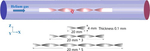
Experiment apparatus was reported in our previous research [Citation12]. The experiment apparatus is composed of gas compressor, flow meter, test section, surge tank, cooler, the heat input control system, and the data measurement and processing system. The vacuum pump was used to degas the loop and test section. The gas was circulated by compressor, and the fluctuations of gas flowing and pressure due to compressor were removed with the surge tanks. Moreover, the cooler and preheater are used to control the gas flow inlet temperature. Flowing rate in the test section was measured with the turbine meter, and the pressure was measured with the pressure transducer. The temperature of the turbine meter exit and the temperature near test section heater were measured by K-type thermocouples with a precision of ±1 K. Helium gas was used as the test fluid. Platinum plates with thickness of 0.1 mm were twisted as the test heaters. The test heater was mounted horizontally along the center part of the circular test channel, which is made of the stainless steel (20 mm in the inside diameter), as shown in . The test heater was heated by direct current from a power source.
Figure 1. Test section.
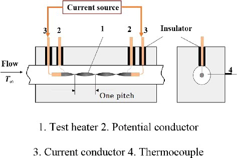
Three twisted heaters with effective length of 26.8, 67.8 and 106.4 mm (pitch number of 1, 3 and 5) were used in this experiment. They were twisted with the same helical pitch of 20 mm. The ends of the heater were connected to two copper plates with the same thickness and then connected to two copper electrodes. Two fine platinum wires (50 μm diameter) were spot welded to the end parts of the twisted plate as potential conductors. The length between the potential taps is defined as the effective length on which transient heat transfer was measured.
2.2. Experimental method and conditions
The heat generation rates of the heater were controlled and measured by a heat input control system with a function of [Citation14], where
is heat generation rate, Q0 is initial heat generation rate, t is time and τ is heat generation period. According to the exponential function, a shorter heat generation period will result in a higher increasing ratio of heat generation. The average temperature of test heater Ta was measured by resistance thermometry using a double bridge circuit including the test heater as a branch [Citation14,Citation15]. The uncertainties of the measurements of the heat generation rate, the heat flux of the test heater and the heater surface temperature were estimated to be ±1%, ±2% and ±1 K, respectively [Citation11].
The heat flux of the heater is calculated by the following equation:
(1)
(1) where ρh, ch and δ are the density, specific heat and thickness of the test heater, respectively.
The instantaneous surface temperature of test heater was calculated by the following equation assuming the surface temperature of test heater to be uniform:
(2)
(2)
Boundary conditions are as follows:
(3)
(3)
(4)
(4) where α (m2/s) and λ (W/(m⋅K)) are the thermal diffusivity and thermal conductivity. Ta (K) is average temperature of the heater.
Physical properties of the fluid were calculated based on the film temperature Tf, where Tf = (Tw + Tb)/2, Tw and Tb are the test heater surface temperature and the bulk temperature of flowing gas, respectively.
Experimental conditions are shown in . The transient heat transfer experimental data were measured for the periods of heat generation rate ranged from 35 ms to 14 s and for the helium gas temperature of 303 K under a system pressure of around 500 kPa. The flow velocities ranged from 4 to 10 m/s, and the corresponding Reynolds numbers (Re) ranged from 2 × 10³ to 3 × 10⁴.
Table 1. Experimental conditions.
2.3. Experimental results and discussion
shows typical experimental data of the time dependence of heat generation rate, , surface superheat, ΔT, and heat flux, q, at the period of 1.4 s. The flow velocity is 10 m/s and gas temperature is 303 K. The heater is the one with effective length of 67.8 mm (three helical pitches). It can be seen that the surface temperature difference and heat flux increases exponentially as the heat generation rate increases exponentially.
Figure 2. Time dependence of , q and ΔT at 10 m/s.
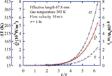
Surface temperature difference is defined as the difference between the average surface temperature of the twisted plate (Twa) and the inlet gas temperature (T∞), expressed as
(5)
(5)
Heat transfer coefficient, h, is defined as shown in the next equation:
(6)
(6)
As introduced in our previous study (Liu et al. [Citation11]), in experiment research the heat transfer coefficient approach constant values from higher initial values when the time passes over a certain time of about two to four times of the period (t/τ > 2–4) according to different periods. And the constant value of heat transfer coefficient, h, is plotted as a single point in and . shows the effect of heater length at various periods and flow velocity of 10 m/s. The heat transfer coefficient, h, becomes to approach asymptotic value at each velocity when τ is longer than about 1 s. On the other hand, when the period τ is shorter than about 1 s, h increases as τ shortens. It has been clarified in the early works that at extremely short period (τ < 100 ms), the conductive heat transfer near the heater comes to govern the heat transfer process, and the heat transfer coefficient increases greatly with shorter period in this region. When period τ is larger than about 1 s, the heat transfer process turns to normal convective heat transfer through the thermal boundary layer influenced by the flow of helium gas. Therefore, in this study, the average value of heat transfer coefficients at periods larger than about 1 s is taken as quasi-steady-state heat transfer coefficient.
Figure 3. Effect of length on heat transfer coefficient at various periods.
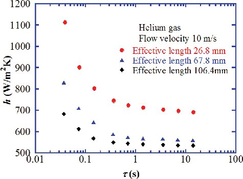
Figure 4. Effect of flow velocity on heat transfer coefficient at various periods.
Moreover, it can be seen from that the heat transfer coefficient decreases with the increase of heater length. The quasi-steady-state heat transfer coefficient for the heater with effective length of 26.8 mm is about 700 W/(m2⋅K), about 24% higher than that of the 67.8 mm heater. While the quasi-steady-state heat transfer coefficient improved only about 5% by comparing the 67.8 mm length heater to the 106.4 mm length heater. Therefore, it can be concluded that the heat transfer coefficient along the length direction of a twisted plate is not constant and the distribution is nonlinear. It is considered that the thermal boundary layer become thick along the flow direction and lead to a lower heat transfer coefficient in the downstream side of the twisted plate. To find the distribution of heat transfer coefficient along the length direction and to clarify the phenomena, numerical simulations will be carried out later in this study.
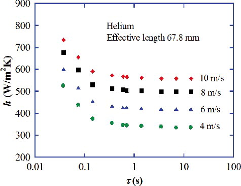
The relation between the heat transfer coefficients and the periods of heat generation rate for the heater at various flow velocities was shown in . The heater is the one with effective length of 67.8 mm (three helical pitches). The heat transfer coefficient increases with the increase of flow velocity. However, the increasing rate decreases. The heat transfer coefficient, h, becomes to approach asymptotic value at each velocity when τ is longer than about 1 s. On the other hand, when the period τ is shorter than about 1 s, h increases as τ shortens.
Manglik and Bergles [Citation8] used a swirl parameter to describe the intensity of the tape-twisted induced secondary motion and it is defined as
(7)
(7) where d is characteristic length and U is velocity.
In this study, the heat transfer enhancement of the twisted plate itself was investigated and a redefined swirl parameter was adopted to indicate the swirl flow effect since the square of Reynolds number becomes very large in magnitude, where
, Us is the swirl velocity and Ls is the helical flow length for the twisted plate, expressed in the following equations [Citation14
]:
(8)
(8)
(9)
(9)
(10)
(10) where L is effective length of the twisted plate (centerline length, m), y is twisted ratio, H is pitch size (m) and W is plate width (m). The helical flow length refers to the helically twisted streamline and can be expressed as shown in
Figure 5. Helical flow length for twisted plate.
The relationship between the Nusselt number and the Sw parameter for various periods ranging from 1.4 to 14 s with flow velocity ranging from 4 to 10 m/s was shown in . Effective length of the twisted plates is 26.8, 67.8 and 106.4 mm, respectively. As shown in the Nust/Prf 1/3 versus Sw graph, the Nusselt numbers for quasi-steady state increases with the redefined swirl parameter Sw. It can be correlated by the following equation:(11)
(11) where
Nust = hstLs/λ, hst(W/m2K) is quasi-steady-state heat transfer coefficient and Pr is Prandtl number (about 0.68 in the range of this experiment).
Figure 6. Quasi-steady-state heat transfer at various swirl parameters.
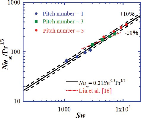
In , maximum error occurs at the one-pitch case with velocity of 4 m/s where the flow is more near laminar region. For Sw larger than 4000, the empirical correlation matches experimental data well, with differences within 10%. As should be noticed, the transition from laminar flow to turbulent flow usually occurs at Re of about 5 × 10⁴ for a flat plate, while for the twisted plate the transition region is considered to occur at a much lower Re due to the disturbing of flow generated by the swirl structure. A similar correlation was obtained by Liu et al. [Citation16] with a different exponent of 0.5 for Sw and in the research Sw ranged from 3000 to 8000. The correlation was plotted by a dotted line as shown in . As can been found, for this small range of Sw, the correlation [Citation16] can express the Nusselt number well. However, in this study, the swirl parameter Sw has a larger range of about 1000 to 20,000. With an overall consideration of the three different lengths, an empirical correlation of EquationEquation (11)(11)
(11) was obtained in this research.
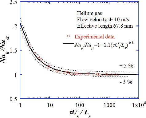
As stated in the introduction, Liu et al. [Citation10,Citation11] carried out experiments on the transient heat transfer of helium gas for cylinders and flat plates. An empirical correlation of the ratio of transient Nusselt number (Nutr) to the quasi-steady-state Nusselt number was obtained using a dimensionless period of τ* (τ* = τU/L, U is flow velocity and L is effective length). The present experimental data can be also correlated using the dimensionless period, τU/L. As shown in , the empirical correlation for twisted plate with different length can be obtained as follows:(12)
(12)
Figure 7. Transient heat transfer for twisted plate at various flow velocities and periods.
As can be derived from EquationEquations (8)(8)
(8) and (Equation9
(9)
(9) ), τUs/Ls equals to τU/L.
It can be seen that the ratios of Nutr to Nust decrease to unity as the dimensionless period τ* increases. The transient heat transfer approaches quasi-steady state one for τ* larger than about 300. The coefficient C equals 4.0, 1.1 and 0.75 for different effective lengths of 26.8, 67.8 and 106.4 mm, respectively. Here, the coefficient C for the shortest 26.8 mm heater is much larger than the other two heaters. It is because the Reynolds number for the shortest heater is about 2000 which is in the region of laminar flow (for a flat plate). In this region, the effect of conductivity takes more important part. Therefore, the increasing ratio of heat transfer coefficient from quasi-steady-state region to transient region for a short heater is larger.
3. Numerical solution
3.1. Physical model
The heater was mounted horizontally along the center axis of the circular channel, which is 20 mm in diameter. The twisted plates are 4 mm in width, 0.1 mm in thicknesses and 20 mm in helical pitch. shows the 3D physical model. Three kinds of effective length with pitch numbers of 1, 3 and 5 were simulated. The model was built with necessary simplification. Forced convection transient heat transfer for helium gas flowing over twisted plate with exponentially increasing heat input was numerically calculated. The inlet and outlet channel length is set to be ten times the tube diameter.
Figure 8. Three-dimensional physical model.
3.2. Basic equations, models and calculating conditions
ANSYS FLUENT 14.0 code was used in this numerical solution. For the fluid, mass, momentum and energy conservation equations take the following forms, respectively [Citation17]
(13)
(13)
(14)
(14)
(15)
(15) where
(16)
(16)
(17)
(17)
(18)
(18)
For the twisted plate, the energy conservation equation takes the following form:
(19)
(19)
Internal heat source is , where
is heat generation rate, Q0 is initial heat generation rate, t is time and τ is period of heat generation rate or e-fold time.
Boundary conditions at heater surface are as follows:
(20)
(20)
(21)
(21)
(22)
(22)
Boundary conditions at the wall of channel are as follows:
(23)
(23)
(24)
(24)
In this study, the Reynolds Stress Model (RSM) was used to model the turbulent flow regime. Because the RSM accounts for the effects of streamline curvature, swirl, rotation and rapid changes in strain rate in a more rigorous manner than one-equation and two-equation models, it has a greater potential to give accurate predictions for complex flows. The convection term was discretized using the second-order upwind scheme, and the linkage between the velocity and pressure was computed using the SIMPLE algorithm. The Enhanced Wall Treatment model was chosen for the near-wall modeling method because it combines the use of a blended law-of-the-wall and a two-layer zonal model and generally requires a fine near-wall mesh that is capable of solving the viscous sub-layer.
The dimensionless distance y+ (= ρuτyn/μ) was considered, where ρ is density (kg/m3), uτis friction velocity (m/s), yn is wall-normal distance (m) and μ is molecular viscosity. To ensure the mesh quality, the first near-wall node is placed at y+ ≈ 1 and over 20 cells were placed in boundary layer. The total mesh number for the one-pitch case is about 0.5 million. Finer mesh with smaller twisting degree and mesh size for the twisted plate and the flow field, more layers in the boundary layer are used to confirm the grid convergence. The total grid numbers increase to 1.2 million. 3D numerical simulation results for the two mesh were compared. Difference for total heat flux and temperature difference between the two mesh is about 0.05% which indicates that the current mesh is fine enough for the calculation.
The calculating conditions of numerical simulation are shown in
Table 2. Calculating conditions.
3.3. Simulation results
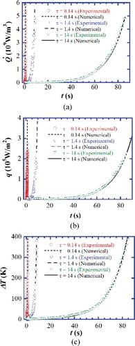
(a)–9(c) show time dependence of heat generation rate, , heat flux, q, and surface temperature difference, ΔT, at various periods of 0.14, 1.4 and 14 s. The flow velocity is 10 m/s and gas temperature is 303 K. The helical pitch of twisted plate is 20 mm and the effective length is 60 mm covering three pitches. Experimental results of the twisted plate with almost same effective length are compared with the numerical simulation results. The symbols show experimental data, and the lines show values of the numerical solution. As shown in (a)–9(c), heat generation rate, heat flux and temperature difference increase rapidly as the period is shorter, and it is understood that the heat flux and surface temperature difference increase exponentially as the heat generation rate increases with exponential function. The simulation results of heat flux and temperature difference agree well with the experimental data within 5%.
Figure 9. Comparison of Q, q and ΔT with experimental data at various periods. (a) , (b) q and (c) ΔT.
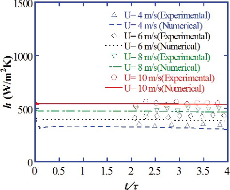
The instantaneous heat transfer coefficients versus times at various flow velocities are shown in . The helical pitch of the twisted plate is 20 mm and the effective length is 60 mm covering three pitches. The period is 1.4 s. Experimental results of the twisted plate with almost same effective length are compared with the numerical simulation results. For the simulation result, the heat transfer coefficient of numerical solution at a definite velocity approaches immediately from a higher value to an asymptotic value. However, the experimental data approach asymptotic values after t/τ > 2 for τ = 1.4 s [Citation11]. The heat transfer coefficients of numerical simulation are compared to the quasi-steady-state values of experiment at various velocities. As seen from the figure, heat transfer coefficient increases with the increase of flow velocity. For higher flow velocities of 8 and 10 m/s, the numerical results agree well with the experimental data, while for lower flow velocities, the simulation values are somewhat lower than experimental data, and the differences are within 7.4%. Therefore, it can be derived that the RSM used in this study showed wide applicability for Reynolds number (Re) ranged from 2 × 10³ to 3 × 10⁴.
Figure 10. Comparison of simulation results with experimental data at various flow velocities.
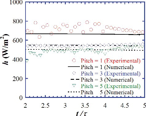
To study the effect of effective length on heat transfer coefficient, three kinds of effective length with pitch numbers of 1, 3 and 5 have been modeled at the period of 1.4 s and the flow velocity of 10 m/s. shows the comparison of simulation results with experimental data for heat transfer coefficients at various effective lengths. As can be seen, the heat transfer coefficient increases with the decrease of effective length. The decreasing ratio of heat transfer coefficient from the shortest heater with one pitch to the three-pitch heater is much larger than that from the three-pitch heater to the five-pitch heater. It indicated that the heat transfer coefficient along the length direction of a twisted plate is not constant and the distribution is nonlinear. Moreover, by comparing to our previous experimental data for a flat plate [Citation12], the heat transfer coefficient for the twisted plate is about 10%–50% higher than that of a flat plate. Therefore, it was considered that with a proper length of twisted heater great enhancement for heat transfer coefficient can be generated.
Figure 11. Comparison of simulation results with experimental data for heat transfer coefficient at various effective lengths.
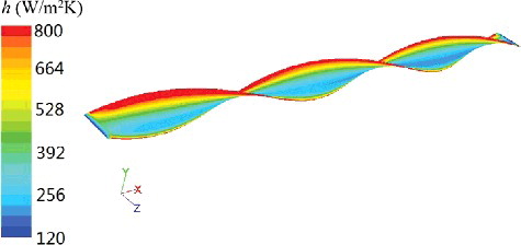
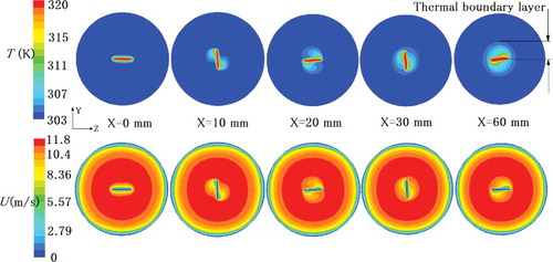
The distribution of heat transfer coefficient on the heater surface is shown in . The heat generation period τ is 1.4 s and the passage time for heat generation is at t = 4.2 s (t = 3τ ). The effective length is 60 mm with three pitches. The flow velocity is 10 m/s. Generally, heat transfer coefficient decreases along the length direction. A larger heat transfer coefficient was generated in the surface of twisted heater that facing the flow which is due to the disturbing of flow caused by the crash between helium gas and the twisted surface. There exists a distribution for the heat transfer coefficient along the width direction. The side facing the flow has larger heat transfer coefficient while smaller heat transfer coefficient exists at the leeward side. The highest heat transfer coefficient exists at both edges of twisted plate where the thermal boundary thickness is very small.
Figure 12. Distribution of heat transfer coefficient on the heater surface.
3.4. Temperature and velocity boundary layer distribution
shows several cross section views of the temperature field in YOZ plane at different locations along the twisted plate. The period is 1.4 s at the flow time of t = 3τ. The flow velocity is 10 m/s. The effective length is 60 mm covering three pitches. It can be found from the figure that generally the temperature boundary layer turns thicker along the x-direction of plate. It results in the increasing of surface temperature along the length direction of the heater. The heat transfer coefficient decreases along the length direction as the thermal boundary layer turns thicker. The velocity boundary layer is alike the temperature boundary layer. It can be seen that the velocity boundary swirls with the twisted plate, and a maximum velocity of over 10 m/s occurs around the heater. It is considered that the swirl structure of twisted plate may induce a swirl flow, and a radial velocity will be generated along the twisted plate, then it contributes to the increased flow velocity.
Figure 13. Cross section of temperature and velocity contours in YOZ plane.
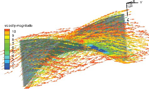
In addition to the effect of increased flow velocity, it is considered that the helical vortices generated by the surface curvature of twisted plate will improve turbulence intensity and promote greater “thermal mixing”. shows the 3D velocity distribution around the center part of the twisted plate. As can be found that a swirl flow was generated along the twisted structure. It will result in sharper temperature gradients in the boundary layer and higher heat transfer coefficient. Therefore, it is considered that the enhancement of heat transfer was attributed to the effects of “thermal mixing” and increased flow velocity.
Figure 14. 3D velocity distribution around the twisted plate.
3.5. Local heat transfer coefficient
As mentioned above, the heat transfer coefficient increases with the decrease of the heater length and the increasing ratio is not linear. The heat transfer coefficient increases about 5% from the five-pitch heater to the three-pitch heater, while the increasing ratio of three-pitch heater to one-pitch heater is about 24%. Thus, it is considered that a shorter heater is of significant influence on heat transfer coefficient.
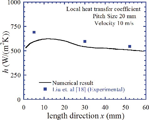
Simulation results for local heat transfer coefficient for the three-pitch case are shown in . Heat transfer coefficient decreases along the length direction though it shows some fluctuations along the heater. Highest local heat transfer coefficient exists at the first pitch and decreases greatly through the second pitch. Then, for the last pitch, heat transfer coefficient almost comes to a stable value. Experimental research for local heat transfer coefficient was reported in our previous research [Citation18]. Experimental data is also shown in for comparison. The experimental data showed almost the same trend of dependence on local length, though they are about 7% to 13% higher than those of numerical values.
Figure 15. Local heat transfer coefficient along the twisted plate.
4. Conclusions
Forced convection transient heat transfer for helium gas flowing over a twisted plate with different length was experimentally and theoretically studied. Following conclusions were obtained.
The heat transfer coefficient for the twisted plate increases with the decrease of effective length.
The heat transfer coefficient through the first twist pitch is much higher than others. A short enough twisted heater would be able to enhance heat transfer greatly.
The empirical correlation for forced convection heat transfer for a twisted plate was obtained and it expresses the experimental data within 10%.
Simulation results of heat flux and temperature difference agree well with experimental data within 5%.
Temperature and velocity distributions on twisted heater were clarified.
Simulation results for local heat transfer coefficient is obtained and compared to our previous experimental data. Generally, it decreases along the length direction.
Acknowledgements
This work was supported by JSPS KAKENHI [grant number 15K05829].
Disclosure statement
No potential conflict of interest was reported by the authors.
| Nomenclature | ||
| ch | = | specific heat of test heater, J/(kg·K) |
| cp | = | specific heat of helium gas, J/(kg·K) |
| d | = | diameter of the circular channel, m |
| E | = | total energy, J/kg |
| g | = | gravitational acceleration, m/s2 |
| H | = | twisted pitch (180°), m |
| h | = | heat transfer coefficient, W/(m2·K) |
| hf | = | enthalpy of the fluid, J/kg |
| hs | = | enthalpy of the solid, J/kg |
| hst | = | quasi-steady-state heat transfer coefficient, W/(m2·K) |
| k | = | thermal conductivity, W/(m·K) |
| keff | = | effective thermal conductivity, W/(m·K) |
| L | = | effective length of the heater, m |
| Ls | = | helical flow length, m |
| Nu | = | Nusselt number, Nu = hLs/λ. |
| Nust | = | quasi-steady-state Nusselt number, Nust = hstLs/λ. |
| Nutr | = | transient Nusselt number (τ < 1 s) |
| p | = | static pressure, Pa |
| Pr | = | Prandtl number |
| = | heat generation rate per unit volume, W/m3 | |
| Q0 | = | initial heat generation rate, W/m3 |
| q | = | heat flux, W/m2 |
| Re | = | Reynolds number |
| Resw | = | Reynolds number based on swirl velocity, UsLs/ν |
| Sw | = | Redefined swirl parameter, |
| T | = | temperature, K |
| Ta | = | average temperature of the heater, K |
| Tw | = | surface temperature of the heater, K |
| Twa | = | average surface temperature, K |
| Tb | = | bulk temperature of the fluid, K |
| ΔT | = | temperature difference, K |
| t | = | time, s |
| U | = | inlet velocity, m/s |
| u | = | X component velocity, m/s |
| uτ | = | friction velocity, m/s |
| v | = | Y component velocity, m/s |
| = | velocity vector of fluid | |
| W | = | width of plate, m |
| w | = | Z component velocity, m/s |
| X | = | coordinate along the axis of the plate, m |
| Y | = | coordinate along the width of the plate, m |
| y | = | twisted ratio, H/W |
| yn | = | wall-normal distance, m |
| Z | = | coordinate along the thickness of the plate, m |
| α | = | thermal diffusivity, m2/s |
| δ | = | plate (heater) thickness, m |
| δij | = | unit tensor |
| ρ | = | density of helium gas, kg/m3 |
| ρh | = | density of the heater, kg/m3 |
| λ | = | thermal conductivity of helium gas, W/(m·K) |
| τ | = | period of heat generation rate or e-fold time, s |
| τ* | = | dimensionless period, τU/L |
| = | stress tensor, N/m2 | |
| τeff | = | deviatoric stress tensor, N/m2 |
| μ | = | molecular viscosity, kg/(m·s) |
| Subscript | ||
| f | = | fluid (helium gas) |
| h | = | test heater |
| s | = | swirl |
| st | = | quasi-steady state |
| t | = | turbulent |
| tr | = | transient |
| w | = | wall surface (heater surface) |
References
- Abram T, Lon S. Generation-IV nuclear power: a review of the state of the science. Energy Policy. 2008;36:4323–4330.
- Soliman M, Johnson HA. Transient heat transfer for forced convection flow over a flat plate of appreciable thermal capacity and containing an exponential time-dependent heat source. Int J Heat Mass Transf. 1968;11(1):27–38.
- Chen Y, Arbeiter F, Heinzel V, et al. Transient conjugated heat transfer within IFMIF high flux test module. Nucl Eng Des. 2012;249:172–179.
- Nakano M, Tsuji N, Tazawa Y. Conceptual reactor design study of very high temperature reactor (VHTR) with prismatic-type core. J Power Energy Syst. 2008;2(2):768–774.
- Travis BW, El-Genk MS. Numerical simulation and turbulent convection heat transfer correlation for coolant channels in a very-high-temperature reactor. Heat Transf Eng. 2013;34(1):1–14.
- Travis BW, El-Genk MS. Thermal-hydraulics analyses for 1/6 prismatic VHTR core and fuel element with and without bypass flow. Energy Convers Manag. 2013;67:325–341.
- Leung CW, Chan TL, Probert SD, et al. Forced convection from a horizontal ribbed rectangular base-plate penetrated by arrays of holes. Appl Energy. 1999;62(2):81–95.
- Manglik RM, Bergles AE. Heat transfer and pressure drop correlations for twisted-tape inserts in isothermal tubes: Part I-laminar flows. J Heat Transf. 1993;115:881–889.
- Hata K, Masuzaki S. Twisted-tape-induced swirl flow heat transfer and pressure drop in a short circular tube under velocities controlled. Nucl Eng Des. 2011;241:4434–4444.
- Liu, QS, Fukuda K, Zheng Z. Theoretical and experimental studies on transient heat transfer for forced convection flow of helium gas over a horizontal cylinder. JSME Int J Ser B. 2006;49(2):326–333.
- Liu, QS, Shibahara M, Fukuda K. Transient heat transfer for forced convection flow of helium gas over a horizontal plate. Experimental Heat Transf. 2008;21:206–219.
- Liu QS, Zhao Z, Fukuda K. Transient heat transfer for forced flow of helium gas along a horizontal plate with different widths. Int J Heat Mass Transf. 2014;75:433–441.
- Zhao Z, Liu QS, Fukuda K. Experimental and numerical study on transient heat transfer for helium gas flowing over a flat plat containing an exponentially increasing heat source. Mechanical Eng J. 2014;1(4):1–13.
- Fukuda K, Liu QS. Steady and transient critical heat fluxes on a horizontal cylinder in a pool of Freon-113. Int J Transp Phenom. 2005; 7:71–83.
- Liu, QS, Shiotsu M, Sakurai A. A correlation for forced convection film boiling heat transfer from a horizontal cylinder. In: Kim JH et al., editors. Two-phase flow and heat transfer. HTD-Vol. 197. ASME Book; 1992. p. 101–110.
- Liu QS, Zhao Z, Fukuda K. Experimental study on transient heat transfer enhancement from a twisted plate in convection flow of helium gas. Int J Heat Mass Transf. 2015;90:1160–1169.
- Ansys fluent theory guide. Canonsburg (PA): Ansys, Inc.; 2012. Available from: http://www.ansys.com
- Liu QS, Zhao Z, Fukuda K. Width effect and local heat transfer characteristics for helium gas flowing over a twisted plate. J Nucl Sci Technol. 2015;53(2):223–231.