
ABSTRACT
Development of fine grain 316L with small amount of TiC for high radiation-tolerant performance was tried considering the fabrication process of thermo-mechanical treatments. The materials obtained are UFG316L+2.0 mass% TiC with the grain size of 90–270 nm, depending on the final annealing temperature from 700 ℃ to 900 ℃. The materials were examined by transmission electron microscopy observation, X-ray absorption near-edge structure spectroscopy, high voltage electron microscope electron irradiation and stress corrosion cracking by crevice bent beam method in high-temperature water with 8 ppm dissolved oxygen. The test results showed that the material is generally of excellent quality. Especially void swelling induced by the electron irradiation at 400 ℃ is less than 1/10 compared to the commercial SUS316L.
1. Introduction
Austenitic stainless steels have been employed extensively for nuclear power reactors for many years, because the materials show very tough mechanical strength and excellent performances in the environment of water coolant exposure and neutron irradiation in high temperature. For much more reliable and safe operation of the nuclear reactors, the structural materials are expected to be developed extensively. Recently, there is a movement to extend the reactor life. In this situation, we have to consider at first the irradiation behavior of the materials in the reactor core. Although void swelling induced by neutron irradiation is the typical severe problem in fast breeder reactors (FBR), it has not been considered so far in the light water reactors (LWR) because the irradiation fluence is much lower in LWR than that in FBR. However, void formation (swelling) was recognized at lower temperature (400 ℃) even in LWR by Garner [Citation1]. It is noticed that swelling–creep interaction in fuel pin cladding may cause the fuel pins to deform into spiral rods. As grain boundaries (GBs) of the poly-crystal materials are great sink for the defects produced by neutron irradiation, fine grain materials are expected to show high radiation-tolerant performance [Citation2,Citation3]. We tried to develop ultra-fine grain austenitic stainless steels (UFG316L) with addition of TiC-nanoparticles. In the previous paper, we reported the fabrication of UFG316L+1.0 mass% TiC, which was examined by neutron irradiation in JMTR (JAEA) and high voltage electron microscope (HVEM) 1.0 MeV electron irradiation. Less hardening and low void swelling in the irradiations by neutron and/or high-energy electron were recognized [Citation4].
We have tried the fabrication of UFG316L+2.0 mass% TiC as the next step of the material development. Since in the previous study the radiation-tolerant properties of 316L steel have been improved by 1.0 mass% TiC addition, it is expected that the properties enhance more with addition of 2.0 mass% TiC. The TiC particles have pinning effects on GB migration, thereby leading to further grain refinement. However, such an increase of TiC content may cause a significant increase in possible cracking sites, such as interfaces between TiC particles and the SUS316L matrix, and resulting in further ductility loss. Therefore, it is necessary to employ advanced fabrication methods that are capable of yielding enhanced ductility and strength in the controlled state of the nanostructures. In this report, the procedure of the advanced material fabrication in Section 2.1, electronic state analysis of TiC in the materials in Section 2.2, HVEM study in Section 2.3, and stress corrosion cracking/crevice bent beam test in Section 2.4 are described.
2. Experimental procedure and results and discussion
2.1. Fabrication of the materials
Powders of SUS316L (an average particle size: 44–105 μm) and TiC (0.57 μm) were used as the starting materials. These powders were mixed to provide the target compositions of SUS316L and 2.0 mass% TiC. These mixed powders together with hard steel balls were put into a vessel made of SUS316L steel and then subjected to mechanical alloying (MA) treatment by vibrational ball milling for 125 h in a purified hydrogen atmosphere (purity: 99.99999%). All of these procedures were conducted in a specially designed glove box that prevents the powders from being contaminated with oxygen and nitrogen in air before and after the MA treatment. Hot isostatic pressing (HIP) treatment was conducted at 850 °C at 196 MPa for 3 h in an argon atmosphere.
The HIPed compacts were subjected to thermo-mechanical treatments (TMTs) to introduce ultra-fine grained, thermally stable nanostructures by using reverse transformation of deformed martensite to austenite. The TMTs include GSMM (grain boundary sliding-based microstructural modification) for toughness enhancement [Citation5] at 950 °C (see ), cold-rolling at 77 K by 76% in reduction ratio for phase transformation from austenite to martensite (77 K is well below Md, the temperature where the martensitic transformation can be triggered by plastic deformation) and isothermal heat treatments at 700 °C–900 °C for 10 min for reverse transformation from martensite to austenite. Details of the fabrication process have been reported elsewhere [Citation6].
Table 1. Effects of thermo-mechanical treatments (TMTs) on grain size of austenite (d), 0.2% proof strength (σ0.2), ultimate tensile strength (σT), uniform elongation (ϵu), and total elongation (ϵT) for UFG316L+2%TiC.
shows X-ray diffraction (XRD) profiles for each of the fabrication states of the UFG316L + 2.0 mass% TiC (UFG316L+2%TiC, hereafter), indicating that the martensitic structure is introduced by cold rolling and reverted to austenite during the heat treatment [Citation6]. In , bright field images of transmission electron microscopy (TEM) for the UFG316L+2%TiC heat treated at 700 °C, 750 °C, 800 °C, and 900 °C after 77 K cold roll treatment are shown, indicating the grain size to be as small as 90, 140, 190, and 270 nm, respectively [Citation6]. It was found, as shown in and , that the UFG316L+2%TiC materials exhibit essentially a single austenitic phase of equiaxed, UFGs and a fine distribution of TiC dispersoids. TiC dispersoids exist both at GBs and within grains, as shown in [Citation6]. The average sizes of TiC existing at GBs are from 70 to 110 nm, while those within grains are from 20 to 50 nm, depending on the heat treatment temperature: The particle sizes at GBs and within grains increase with the increasing heat treatment temperature from 700 °C to 900 °C.
Figure 1. XRD profiles for each fabrication state of UFG316L+2%TiC: (a) as-HIPed at 850 °C, (b) as-GSMM treated at 950 °C, (c) as-rolled at 77 K, as-heat treated at (d) 700 °C, (e) 800 °C, and (f) 900 °C.
Figure 2. TEM bright field images for UFG316L+2%TiC heat treated at (a) 700 °C, (b) 750 °C, (c) 800 °C, and (d) 900 °C after 77 K cold-roll treatment.
Figure 3. TEM bright field images for TiC particles existing at grain boundaries (a–c) and within grains (d–f) in UFG316L+2%TiC heat treated at 700 °C, 800 °C, and 900 °C after 77 K cold roll. TiC particles are indicated by the arrowheads.
Tensile tests at room temperature (RT) showed the yield strengths (0.2% proof strength) of 0.9 to 1.85 GPa, tensile strengths of 1.1 to 1.92 GPa and uniform elongations of 0.6%--21% () [Citation6]. It should be noted that the nanostrutured UFG316L+2%TiC exhibits a wide range of strengths and elongations and such superior tensile properties are achieved by the advanced fabrication processes shown in this paper, i.e. MA, HIP, GSMM, rolling at a temperature below Md and heat treatments from 700 °C to 900 °C.
It was also found that there is the Hall–Petch relation between the yield stress and d−1/2, where d is the average grain size, although upward deviation of data point at the highest yield stress (or the smallest grain size) from the Hall–Petch relation was observed. This indicates that the yield stress is substantially controlled by the grain size and the contributions of TiC particles to the yield stress is appreciable for the smallest grain size because the very small austenite grain size of 90 nm and relatively large TiC particle size of 20 nm in the grain interior result in a limited grain interior region of the austenite matrix where dislocations can glide to produce uniform elongation. It is thus inferred that the superior mechanical properties of UFG316+2%TiC is attributed to the combination of great malleability in the austenitic matrix phase and grain size effects, and additionally dispersion hardening for the grain size as small as 90 nm.
2.2. Electronic state of TiC in UFG316L+2%TiC
In the fabrication of fine-grained 316L materials, addition of 2 mass% TiC is found extremely effective to control the grain size, as described above. It is suggested that TiC nanoparticles act to fasten the GB move and depress the grain growth in the fabrication process in high temperature.
We tried to measure the electronic states of Ti-L shell in the UFG316L+2%TiC materials in order to elucidate the behavior of Ti or TiC in the fabrication process. X-ray absorption near-edge structure (XANES) spectroscopy was performed at the end-station of the undulator beamline BL-09A in the 1.5 GeV synchrotron light source, NewSUBARU, in the University of Hyogo [Citation7,Citation8]. The data were collected by a total electron yield mode in which the sample current was measured when the photo-electron was emitted by soft X-ray absorption. The values were normalized with a simultaneously recorded photoemission signal from a gold mesh, which indicate the soft X-ray intensity incident into the sample. At the present time, XANES spectra of Ti-L absorption edge of TiC in the UFG316L+2%TiC materials were measured.
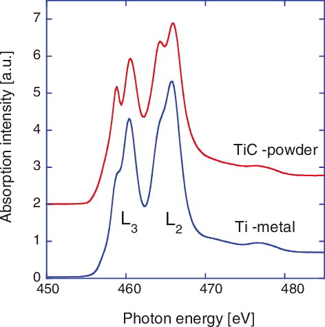
shows Ti-L2,3 absorption spectra for pure Ti (99.99%) metal and TiC powders measured for reference before the XANES study for the fabricated UFG316L+2%TiC materials. A peak of Ti-L2 (2p1/2) and L3 (2p3/2) was observed at 465.8 and 460.4 eV, respectively, in the Ti-metal specimen. On the other hand, each of L2 and L3 spectral line exhibits twin peak structure with an additional line with a separation of about 1.5 eV for the TiC powder specimen. By the line spectrum deconvolution, it is decided that the Ti-2p spectra of the TiC powder are separated to two peaks (463.4 and 465.8 eV) for L2, and other two peaks (458.8 and 460.4 eV) for L3. The energy data of these lines are in good agreement with the previous report [Citation9]. The spectral variation is reflected by the electronic structure due to different chemical state of Ti [Citation10,Citation11].
Figure 4. Ti-L2,3 edge XANES spectra of Ti metal and TiC powder.
shows XANES spectra of Ti-L2,3 for the UFG316L+2%TiC specimens. Three kinds of treatments, that is, (a) as HIPed, (b) high-temperature compressed, and (c) cold-rolled, are examined. The XANES spectra observed show characteristic twin peak structure for both L2 and L3, which are in general agreement with the spectra shown in TiC powders (). The XANES spectra of UFG316L+2%TiC (as HIPed) are decomposed as shown in . The black line denotes as the measurement, the green line as decomposed, and the red line as superposition of the decomposed lines. The Ti-L2,3 spectra are separated to two peaks (463.8 and 465.5 eV) for L2, and other two peaks (458.7 and 460.3 eV) for L3. The lower energy peak in L2 is t2g (π-type bonding formed by Ti3dxy, dxz, dyz orbitals and C2p orbitals), and the higher energy peak is eg (σ-type bonding formed by Ti3dx2–y2, dz2 orbitals and C2p orbitals) due to the crystal field of surrounding C atoms with the NaCl-type structure [Citation12]. Likewise the lower energy peak in L3 is due to t2g, and higher energy peak in eg.
Figure 5. Ti-L2,3 edge XANES spectra of UFG316L+2%TiC materials. (a) As HIPed, (b) high-temperature compressed, and (c) 77 K cold-rolled.
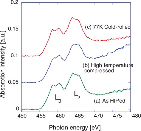
Figure 6. Decomposition of the Ti-L2,3 edge XANES for UFG316L+2%TiC as HIPed. The black line denotes as the measurement, the green line as decomposed, and the red line as superposition of the decomposed lines.
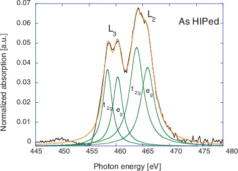
The energies of the peaks in the UFG materials coincide with the corresponding peaks in the TiC powder. However, the eg peaks are smaller than the t2g peaks for both L2 and L3 in UFG316L+2%TiC compared with the TiC powder. The real reason of this feature is not known, but some kind of structural deformation in local Ti-C bonding should be suggested. It could be concluded almost of all Ti atoms exist in the form of TiC in the UFG materials, but, in the same time, it is suggested other kind of precipitates such as carbides exist with scarce concentration in the matrix. The present fabrication procedure for UFG316L+2%TiC is encouraged by the fact that the electronic states of TiC are always unchanged, even if any TMT like high-temperature compression and/or cold-rolling is made.
2.3. HVEM electron irradiation of UFG316L+2%TiC
As useful method to investigate the radiation effects of reactor-core structural materials, irradiation using high-energy charged particles like ions or electrons has been often employed [Citation13,Citation14]. In the present experiment, in situ observation of the defects evolution in UFG316L+2%TiC materials was performed during the material irradiation with 1.0 MeV electron beam in the HVEM facility in Hokkaido University, Japan.
(a–d) shows the microstructure images of the same area, which are indicated by arrow (and dotted circular) in each figure of the UFG316L+2%TiC materials (for the specimen C-20) irradiated at 400 °C by 1.0 MeV electrons for about 60 min, up to the final irradiation fluence of 7.2 dpa (displacement per atom). The specimen (C-20) is the materials annealed at 800 °C, in order to obtain reverse transformation of deformed martensitic to austenite, after TMTs and 77 K cold-roll treatment, as described in the Section 2.1. (a) is the microstructure before irradiation. The electron diffraction pattern in the figure is obtained for the selected area of aperture with 10 µm diameter. This specimen is composed of many fine grains of around 150∼200 nm. (b) shows the microstructure after 2.4 dpa irradiation of the same area as (a), although the microstructure contrast is different from each other because the specimen was slightly tilted for the void observation. It would be considered that very small voids (smaller than 8 nm) are already nucleated even in the early stage of the irradiation, and some of them are masked by the dislocation network in the host materials. However, those voids are so small that the contribution to the swelling must be ignored. With increasing the irradiation dose to 4.8 dpa, the voids became observable and voids number density increased as shown in (c). The void formation was more clearly observable after the irradiation up to 7.2 dpa as shown in (d), but the void size (about 8 nm) seemed not to increase being compared with the lower irradiation dose as shown in the magnified photos in the figure (circular area). The swelling is calculated 0.01% at 7.2 dpa.
Figure 7. Microstructural evolution under electron irradiation at 400 °C, for UFG316L+2%TiC (specimen C-20), (a) 0 dpa (non-irradiated), (b) 2.4 dpa, (c) 4.8 dpa, and (d) 7.2 dpa. The specimen C-20 is annealed at 800 °C, after the TMTs treatment and cold-rolling at 77 K. The arrows in the figures indicate the same location of the specimen under irradiation.
shows TEM microstructures with locally magnified structures showing voids and selected area diffraction patterns of other three specimens of UFG+2%TiC (the specimen: C-7, C-11, and C-3), after the irradiation at 400 °C up to 7.2 dpa. The specimens C-7 ((a)) and C-11 ((b)) are annealed at 700 °C, and 900 °C, respectively, after the TMTs treatment and cold-rolling at low temperature (77 K). It is shown in both specimens that very high-density dislocation and some void formation were induced by the irradiation. The void formation and induced swelling are almost of the same order as C-20 as shown in (d). The specimen C-3 ((c)) is the materials treated by higher GSMM treatment temperature at 950 °C after the HIP consolidation. The specimen C-3 has larger grain size of around 610 nm, presumably due to higher treatment temperature than others (900 °C). The ring diffraction pattern of each specimen shown in is mostly from crystal zone axis (111), (002), (022), (113) of FCC structure. As being observed from the diffraction pattern of each specimen, the grain size of the specimen became larger with higher TMTs treatment temperature. The specimen C-3 shows the microstructure of very low dislocation density, and void distribution is relatively uniform, though the void size (about 8 nm) is almost the same as other specimens.
Figure 8. Microstructure of UFG316L+2%TiC after electron irradiation at 400 °C, up to 7.2 dpa for (a) the specimen C-7, (b) the specimen C-11, and (c) the specimen C-3.
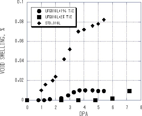
shows the swelling as a function of the irradiation fluence, dpa. The swelling data of the C-20 specimen are compared with the commercial normal-grained SUS316L and UFG+1%TiC, which (the latter two) were reported in the previous report [Citation4]. As shown in this diagram, amounts of the swelling of these steels increase with increasing the fluence of the irradiation. The swelling of the commercial normal-grained SUS316L steel increases up to 0.08% at 5 dpa. On the other hand, the UFG316L+1%TiC specimen shows extremely slow increment of swelling with less than 0.01% in the same dpa range. It is found in this study that the material with 2.0 mass% TiC reveals much more effect to suppress the void formation in comparison with the 1.0 mass% TiC materials until the fluence increases up to 6 dpa, though in much higher fluence than 6 dpa, the void swelling data are almost the same level for both materials.
Figure 9. Void swelling as a function of dpa, for SUS316L, UFG316L+1%TiC, and UFG316L+2%TiC.
It is confirmed that TiC addition of 1 to 2 mass% is quite effective to prevent the defects evolution and void formation during high-energy electron irradiation. It is understood that many of the radiation-induced defects could be annihilated at the GB, because small TiC dispersoids reduce the grain growth owing to the pinning function for GB, and thick network of the GB works as great sink for the defects. The TiC dispersoids in the host grain (austenite matrix) are also considered effective to depress defects evolution, because it has been found there is the following orientation relationship, (11)γ//(001)TiC, (110)γ//(110)TiC, and (12)γ//(10)TiC, and the interface between them would be effective sink to interstitial atoms and vacancies produced by the electron irradiation [Citation6].
2.4. Stress corrosion cracking of UFG316L+2%TiC
In LWR in nuclear power plants, austenitic stainless steels like SUS316 have been extensively used. SCC has been sometimes observed in the materials, and is noticed with one of the most serious materials problem in the environment together with radiation-induced deterioration. The SCC property test is frequently conducted by CBB method in high-temperature water containing 8 ppm dissolved oxygen.
The materials of UFG316L+2%TiC were tested by the CBB method at 562 K (289 °C), and 7 MPa for 3000 h (10.8 Ms). The specimens investigated are listed in . The specimen sizes are shown in the table. The specimen ①, ②, and ③ are the materials as just HIP treated at 1273 K (1000 °C). The thickness of the specimen is 2.0 mm. Specimen ④ is the specimen for reference (1.5 mm thick), which is fabricated by 78% compressive straining at 1273 K (TMTs treatment), and then 60% compressive straining at RT, after HIP treatment at 1123 K.
Table 2. Condition and size of each specimen examined by the CBB test.
After the CBB test, all specimens were examined in order to find the cracks on the surface by optical microscope. Several cracks due to SCC were observed in every specimen surface. After the surface observation, each specimen was cut into halves along the longitudinal direction in order to examine the cross section. Several cracks were found in specimens ②, ③, and ④, but no crack in specimen ①. The number of the cracks and the crack depth found in the cross section of each specimen are shown in . Several cracks with depth of about 1000 µm were found in specimens ② and ③, and, as shown in , typical GB cleavage was observed, suggesting IGSCC occurrence. In specimen ④, there is only one crack which is straight and penetrating from the front surface to backside with the length over than 1500 µm.
Figure 10. Crack depth observed in the cross section of the CBB test specimen. Number of the cracks detected is four, three, and one for the specimens, ②, ③, and ④, respectively.
Figure 11. Optical micrographs of SCC observed in the cross section of the specimen ② after the CBB test.
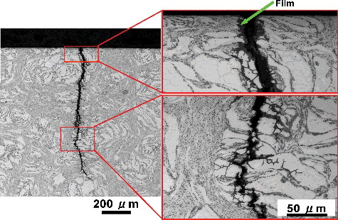
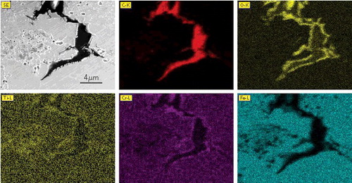
Inside of the cracks is covered with a thin film with several µm thick, as shown in . In order to investigate the elemental distribution around the crack, EDX analysis was made with scanning electron microscope (SEM). The SEM micrograph and EDX maps of C, O, Ti, Cr and Fe distribution in the crack-tip area were obtained, as shown in . High concentration of O and Cr was found on the crack surface, which is suggesting that the oxide formation could promote the crack evolution in the materials. Some increment of Ti near the edge of crack, which may be reflected as the existence of TiC particles at the GB, was observed. Thick concentration of carbon was revealed inside the cracks. It must have come from graphite wool which was inserted between the specimen surface and the holder in the CBB examination.
Figure 12. SEM micrograph and EDX maps of C, O, Ti, Cr, and Fe distribution in the crack-tip area. Carbon image indicates intrusion of graphite into the crack.
Cross sections of the specimens were observed by means of FE (field emission)-SEM equipped with EBSD (electron back scatter diffraction) system, and also observed with a conventional SEM-EBSD system, in the latter case, the cross sections were electropolished with a HClO4 : C2H5OH = 1:9 solution at 12 V for 120 sec. Imaging with SEM-EBSD is based on the orientation analysis of Kikuchi pattern obtained on each measuring point in scanning. Image quality (IQ) map represents the clearness of the Kikuchi pattern, which is deteriorated by lattice defects such as dislocations. Therefore, highly strained areas are shown with dark contrast. At subgrain boundaries and grain boundaries, IQ values are lowered, which also results in dark contrasts. Inverse pole figure (IPF) map represents the orientation at the point with colors indicated in a standard stereographic triangle.
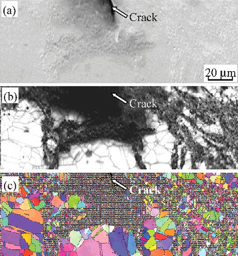
Microstructures near a crack in specimen ③, which were observed with the conventional SEM-EBSD system is shown in . There are two regions with fine grains and coarse grains as shown in (b) and (c). The crack propagated in the fine-grained region, while a small crack is formed in the coarse-grained region as indicated by the white arrow. The bimodal structure of fine and coarse grains in the material is considered due to the partially enhanced grain growth in the HIP treatment at high temperature (1000 ℃), which is a different condition of the HIP process shown in in Section 2.1. (a) shows that the crack extends from the right upper part to the left lower area. The tip of the crack exists at the boundary of coarse grain as indicated by white arrows. There seems no crack in the middle region surface where many fine grains exist, as shown in the IPF map. It could be suggested that the crack detours deep inside the fine grain region. Specimen ②, as shown in , is also composed of two regions with fine grains and coarse grains like those observed in specimen ③. The crack indicated with the white arrows in seems to propagate and be arrested in the fine-grained region.
Figure 13. Microstructures in the specimen ③. (a) SEM image, (b) IQ map, and (c) IPF map.
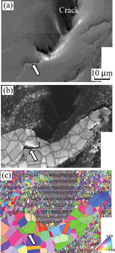
Figure 14. Microstructures in the specimen ②. (a) SEM image, (b) IQ map, and (c) IPF map.
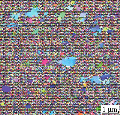
shows higher resolution IPE map of specimen ④ obtained with the FE-SEM-EBSD system. The microstructure would consist of fine grains or would be highly strained probably due to martensitic transformation during rolling at RT [Citation6]. Grains with sub-micron sizes can be seen clearly.
Figure 15. IPF map observed with FE-SEM-EBSD system on the specimen ④.
According to the previous paper on the SCC/CBB examinations in the material of SUS316L with Hv 270, which was fabricated by 20% cold-rolling after solution annealed, average crack depth of 150 µm was observed for 500 h test [Citation15]. The depth would correspond to be about 900 µm for 3000 h, if it could be assumed that the crack grows proportionally with time. Considering the present CBB experiment for the UFG316L+2%TiC materials, both of the specimens ② and ③ have the surface hardness of Hv 283 and 281, respectively, and show the average crack depth of about 1000 µm for 3000 h.
It could be understood that the materials developed in this study indicate almost the same characteristics as the conventional SUS316L steel, which has been recognized as the best practical material on the SCC property in high-temperature water environment of nuclear power plants. The corrosion property is typical statistical problem, and we need to take enough data by executing many examination tests in order to have final decision in advanced material development.
3. Conclusion
Development of fine-grained 316L with addition of small amount of TiC for high radiation-tolerant performance was tried considering the advanced fabrication process of TMTs, including GSMM for toughness enhancement, rolling at a temperature below Md for phase transformation from austenite to martensite and isothermal heat treatments for reverse transformation from martensite to austenite, after MA and HIP treatment. The materials fabricated is UFG316L+2.0 mass% TiC with the grain size of 90–270 nm, depending on the final annealing temperature from 700 ℃ to 900 ℃. The materials microstructure and the electronic structure of TiC in the materials were examined by TEM observation, and XANES spectroscopy using the 1.5 GeV synchrotron radiation. The existence of small TiC dispersoids was confirmed. It was suggested that UFG316L+2.0 mass% TiC was fabricated by suppression of grain growth due to the pinning effect of TiC dispersoids for GB.
Excellent radiation-tolerant behavior of UFG316L+2.0 mass% TiC was confirmed by HVEM 1.0 MeV electron irradiation. Void swelling induced by the irradiation at 400 ℃ was 0.01% at 7.2 dpa, which is less than 1/10 compared to the normal SUS316L. The materials with 2% TiC revealed even smaller swelling than in the material with 1% TiC up to around 6 dpa, though the radiation behavior in higher fluence seems the same for both materials.
SCC by CBB method in high-temperature water with 8 ppm dissolved oxygen was studied. The test results shown in this experiment were rather reasonable and quite similar to the result reported for normal 316L materials which are generally employed so far, though the specimen number in the present experiment is limited, and further more study should be executed.
It is concluded that UFG316L+2.0 mass% TiC is one of the candidate materials with excellent radiation-tolerant property in the future nuclear power reactor application .
Acknowledgments
This work has been performed under the support by 2007–2010 FY Grant-in-Aid for Science Research (S) by JSPS, [Task No. 19106017] ‘Comprehensive study on material damage mechanism by experimental and theoretical methods and development of materials for high-energy quantum-beam fields.’ Some work of the materials fabrication was carried out at the International Research Center for Nuclear Materials Science, Institute for Materials Research, Tohoku University. The authors would also like to thank the staffs for providing the HVEM facility and for their helpful experimental support, and also express their thanks to the Integrated Center for Scinces (INCS), Ehime University for use of their TEM (JEM-2100).
Disclosure statement
No potential conflict of interest was reported by the authors.
Additional information
Funding
References
- Garner FA. Consequences of void swelling and irradiation creep interactions on the performance of austenitic internal components of PWRs. In: 1st International Workshop on Voids in In-core Structural Materials in LWR; 2003 Dec 15; Kyoto, Japan.
- Kurishita H, Kitsunai Y, Shibayama T, et al. Development of Mo alloys with improved resistance to embrittlement by recrystallization and irradiation. J Nucl Mater. 1996;233–237:557–564.
- Kitsunai Y, Kurishita H, Narui M, et al. Effect of neutron irradiation on impact properties of TiC-dispersed molybdenum alloys. J Nucl Mater. 1996;239:253–260.
- Matsuoka H, Yamasaki T, Zheng YJ., et al. Mechanical properties of ultra-fine grained SUS316L steels after neutron irradiation. In: Proceedings of International Congress on Advances in Nuclear Power Plants (ICAPP05) in cooperation with IAEA; 2005 May 15–19; Seoul, Korea (paper 5687).
- Kurishita H, Arakawa H, Matsuo S, et al. Development of nanostructured tungsten based materials resistant to recrystallization and/or radiation induced embrittlement. Mater Trans. 2013;54:456–465.
- Sakamoto T, Kurishita H, Matsuo S, et al. Development of nanostructured SUS316L-2%TiC with enhanced tensile properties. J Nucl Mater. 2015;466:468–476.
- Niibe M, Mukai M, Miyamoto S, et al. Characterization of light radiated from 11 m long undulator. Synchrotron radiation instrumentation. AIP Conf Proc. 2004;705:576–579.
- Ando A, Amano S, Hashimoto S, et al. Isochronous strage ring of the NweSUBARU project. J Synchrotron Rad. 1998;5:342–344.
- Magnuson M, Wilhelmsson O, Palmquist J-P, et al. Electron structure and chemical bonding in Ti2AlC investigated by soft x-ray emission spectroscopy. Phys Rev B. 2006;74(19):195108.
- Mizuno M, Tanaka I, Adachi H. Chemical bonding in titaniumu-metalloid compounds. Phys Rev B. 1999;59:15033–15047.
- Mizoguchi T, Tanaka I, Yoshioka S, et al. First-principles calculation of ELNES and XANES of selected wide-gap materials: Dependence on crystal structure and orientation. Phys Rev B. 2004;70:045103.
- De Groot FMF, Fuggle JC, Thole BT, et al. L2,3 x-ray-absorption edges of d0 compounds: K+, Ca2+, Sc3+ and Ti4+ in Oh (octahedral) symmetry. Phys Rev B. 1990;41:928–937.
- Terasawa M, Nakahigashi S, Kamei H, et al. Void swelling and microchemical segregation in ion-irradiated 316 stainless steel. J Nucl Mater. 1981;103–104:1017–1022.
- Ohnuki S, Hidaka Y, Takahashi H, et al. Effect of helium on defect cluster formation in modified 316 stainless steel irradiated by electron/ion dual beams, J Nucl Mater. 1992;191–194:1134–1138.
- Kuniya J, Kasahara S, Anzai H, et al. Stress corrosion cracking susceptibility of various solution annealed austenitic stainless steels in high temperature water. Zairyo-to-Kankyou. 2007;56:22–28.