
 ?Mathematical formulae have been encoded as MathML and are displayed in this HTML version using MathJax in order to improve their display. Uncheck the box to turn MathJax off. This feature requires Javascript. Click on a formula to zoom.
ABSTRACT
A code PNCMC (Program for Natural Circulation under Motion Conditions) has been developed for natural circulation simulation of marine reactors. The code is based on one-dimensional two-fluid model in noninertial frame of reference. The body force term in the momentum equation is considered as a time dependent function, which consists of gravity and inertial force induced by three-dimensional ship motion. Staggered mesh, finite volume method, semi-implicit first order upwind scheme and Successive Over Relaxation (SOR) method are used to discretize and solve two-phase mass, momentum and energy equations. Single-phase natural circulation experiments under rolling condition performed in Institute of nuclear and new energy technology of Tsinghua University and two-phase natural circulation experiments under rolling condition performed by Tan and colleagues are used to validate PNCMC. The validation results indicate that PNCMC is capable to investigate the single-phase and two-phase natural circulation under rolling motion.
1. Introduction
Innovative small (less than 300 MWe) and medium (between 300 and 700 MWe) sized reactors are highly valued in both developing and developed countries. The Intensified efforts on small and medium reactors (SMRs) designs and research generally aim to provide increased benefits in the area of safety and security, as well as power generation flexibility. Apart from being designed as land-based nuclear power plants, small and medium sized light water reactors (LWRs) can be mounted on a barge as FNPPs (floating nuclear power plants) or as propulsion power. For example, the SMART 330 MW integral pressurized water reactor was designed for seawater desalination, small-scale power generation and ship propulsion. KLT-40s is an upgraded version of ice-breaker ship reactor KLT-40, which is designed for FNPP. So, operating in the ocean becomes an important development trend of small and medium sized LWRs. Most notably, natural circulation is widely used in the design of small and medium sized LWRs, such as ABV-6M, VK-300, NuScale and IMR [Citation1]. Almost all the small and medium sized LWRs introduce passive residual heat removal systems, and the essence of these systems is also natural circulation.
However, during operation in the ocean, the sea wave together with wind induce the barge rolling, pitching and heaving, and these motions affect the reactor thermal hydraulics, especially natural circulation behavior [Citation2]. The effects of ship motion focus on two principles. First, inclination decreases the height difference between the source (core) and sink (steam generator [SG]), and thus decreases the thermal driving head of natural circulation; Second, inertial forces imparted by the ship motion in addition to the gravity act upon the primary coolant, which together with flow resistance change the natural circulation flow rate. The direction and magnitude of inertial forces imparted by rolling depend on the position of rolling axis, rolling acceleration and reactor system arrangement in three-dimensional space. So the natural circulation behaviors under ocean conditions are much more complicated.
Hence considering the nuclear safety, a ton of research activities aiming at investigating natural circulation under motion condition have been performed over the years. Japan Atomic Energy Research Institute (JAERI) conducted experiments using the first Japanese experimental ship Mutsu in various sea conditions to investigate the behavior of the whole marine reactor system from May 1991 to February 1992 [Citation3]. They measured the parameters of wave height, wind force, ship motion (acceleration) and reactor thermal hydraulics; the results indicated that the ship motions hardly affect the operation parameters of primary loop (forced circulation loop), but prominently affect the steam generator water level, evaporator steam void fraction and recirculation flow rate. To study the effects of heaving motion on two-phase flow dynamics of marine reactor, Ishida et al. mounted a small scale rig on a suspended platform oscillated in vertical direction by hydraulic device [Citation4]. Murata et al. performed a series of single-phase natural circulation tests in a model reactor with rolling motion to investigate effects of the rolling motion on thermal-hydraulic behavior [Citation5]. Tan et al. also mounted a flow loop on a rolling platform and carried out a series of experiments to study single-phase natural circulation flow, heat transfer and two-phase flow instability [Citation6,Citation7]. Yan and Yu mounted a Passive Residual Heat Removal System (PRHRS) apparatus on rolling equipment to investigate operational characteristics of passive residual heat removal system under rolling motion [Citation8]. The experimental results indicate that loop flow rate oscillates with ship motions and two-phase natural circulation instability may overlap flow oscillation induced by ship motions.
In addition to experiments, a lot of work on theoretical analysis and code modifying have been done to study reactor thermal hydraulics under ocean condition [Citation9,Citation10]. Yan et al. modified the RELAP5 code by adding a module calculating the effect of rolling motion and introducing new flow and heat transfer models to investigate the thermal-hydraulics behavior of nuclear power systems [Citation11]. JAERI developed RETRAN-02/GRAV code, which was a modified version of RETRAN-02 code, to simulate the experimental voyages of Mutsu and to analyze the effects of ship motions on natural circulation of deep sea research reactor DRX [Citation12]. RETRAN-03/MOV code for simulating ship reactor under multi-dimensional motions was also developed from RETRAN-03 in Seoul National University [Citation13].
China plans to build FNPP with proprietary intellectual property rights in the 13th Five-Year Plan. A totally new code PNCMC (Program for Natural Circulation under Motion Conditions) written in C++ language is developed to simulate the natural circulation of FNPP, which is also required to easily add new models, processes and components. One-dimensional two-fluid model in noninertial frame of reference is proposed in this study. Staggered mesh, finite volume method and semi-implicit first order upwind scheme are used to discretize and solve mass, momentum and energy equations. PNCMC code is also verified by single-phase and two-phase natural circulation experimental data.
2. Two-fluid model in noninertial frame of reference
When studying the thermal hydraulic of marine reactor that has an accelerated motion relative to the ground, if taking the ground as the frame of reference, the flow of fluid is a combination of the reactor motion relative to the ground and fluid motion relative to system boundary (pipe wall). However, if we build a noninertial frame which has the same motion as reactor, the flow of fluid in this frame is just the fluid motion relative to the system boundary, which is the main concern in most engineering fields. The boundary condition is changed from the moving condition in inertial frame of reference to stationary boundary condition in noninertial frame of reference; so the mathematical description of flow is simplified.
Thermal dynamic variables and net viscous stress are independent of the frame of reference and the continuity and energy equations are unchanged in a noninertial frame of reference. The primary effect of a noninertial frame is the addition of extra body force term to the momentum equations, and the extra body force term named inertial force arises from the motion of the noninertial frame.
Combining dynamics of mass point in noninertial frame with two-fluid model in inertial frame [Citation14], one-dimensional two-fluid model in noninertial frame of reference is proposed as follows:
Gas continuity equation:
(1)
(1)
Liquid continuity equation:
(2)
(2) where h*g, h*f associated with bulk interface mass transfer are defined as
(3)
(3) η = 1 for Γig ⩾ 0 and η = −1 for Γig < 0.
Gas momentum equation:
(4)
(4)
Liquid momentum equation:
(5)
(5)
Gas energy equation:
(6)
(6)
Liquid energy equation:
(7)
(7) where ξh is heating perimeter, Ais the cross area of flow channel, Tw is wall temperature, Hwg, Hwf is volumetric wall heat transfer coefficient for gas and for liquid, respectively, Φ is phase energy dissipation terms. h′g, h′f associated with near wall mass transfer are defined as
(8)
(8) ϵ = 1 for Γwg ⩾ 0 and ϵ = −1 for Γwg < 0.
The constitutive relations include models for defining flow regimes and flow regime-related models for total interfacial shear force Mdg, wall friction and
, wall heat transfer coefficient Hwg and Hwf, interphase heat transfer coefficient Hig and Hif. In PNCMC, the constitutive relations are in accordance with that used in RELAP5/MOD3.3, and the detailed description of those can be found in RELAP5/MOD3 code manual volume IV [Citation15].
3. Inertial forces arise from ship motion
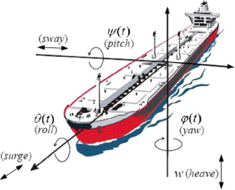
As shown in , the ship motion can be decomposed into swaying, pitching, yawing, heaving, rolling and surging. The axis and amplitude of rolling and pitching can be given by ship design compartment. Among these six modes of motion, pitching, heaving and rolling have significant impact on reactor natural circulation, which are the emphasis of our research. Most often, we tend to study pitching and rolling separately, that is because intense pitching and rolling are not coexisting.
Figure 1. Ship movement – the six degrees of freedom.
The inertial forces of a fluid particle are obtained in this general expression,
(9)
(9)
The four terms in the brackets of EquationEquation (9)(9)
(9) are all significant. The first term a0 accounts for the acceleration of noninertial frame relative to stationary frame. It provides the apparent force that pushes occupants back into their seats or makes them tighten their grip on a handrail when a vehicle accelerates. The second term
is the acceleration caused by angular acceleration of the noninertial frame, so it is of little importance for geophysical flows or for flows in machinery that rotate at a constant rate about a fixed axis. However, it does play a role when rotation speed or the direction of rotation varies with time. The third term ω × (ω × r) is the centripetal acceleration, which depends strongly on the rotation rate and the distance of the fluid particle from the axis of rotation. The final term 2ω × V is the Coriolis acceleration, depending on the fluid particle's velocity, not on its position.
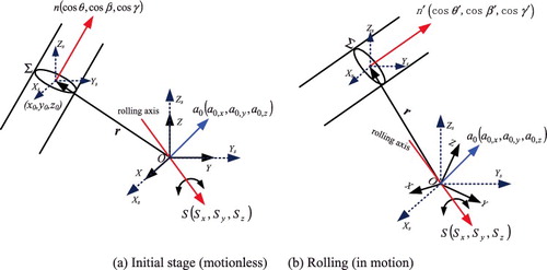
In , one noninertial frame OXYZ with coordinate unit vector i j k and one stationary frame OXsYsZs is built. The origin O is set on the rolling axis. At initial stage, noninertial frame OXYZ and stationary frame OXsYsZs are overlapping, the unit vector is straight up and contrary to gravity. Noninertial frame OXYZ has a rolling motion around axis S = (Sx, Sy, Sz) and acceleration a0 = (a0, x, a0, y, a0, z) relative to stationary frame. Σ is an arbitrary cross section of channel and points in Σ belong to the domain {x0 ± Δx, y0 ± Δy, z0 ± Δz}. The unit vector n = (cos θ, cos β, cos γ) represents for positive main stream of channel in noninertial frame OXYZ.
Figure 2. Geometry showing flow channel and noninertial frame.
The rolling of ship is similar to sine wave and is expressed as
(10a)
(10a)
(10b)
(10b)
(10c)
(10c) where φ is rolling angle, φm is the rolling amplitude and ϖd is the rolling frequency.
According to EquationEquation (9)(9)
(9) , fine is obtained as
(11)
(11)
The flow field in a channel is actually three-dimensional, but the velocity of main stream is much greater than that of cross section, which is suitable for most flow channels. The Coriolis acceleration is perpendicular to velocity, so the component of Coriolis acceleration along main stream is ignored in PNCMC. Then fine, n is simplified as
(12)
(12)
For reactor systems and system experimental facilities, the pipeline cross-sectional scale (Δx,Δy,Δz) is much smaller than system spatial scale (x0,y0,z0); so we can assume that
(13)
(13)
So fine, n is approximately uniform in cross section Σ.
Then ⟨fine, n⟩ is written as
(14)
(14)
⟨fine, n⟩ is changed to ⟨fine, z⟩ in EquationEquations (4)(4)
(4) and (Equation5
(5)
(5) ).
During rolling, gz changes with the angle between channel and vertical direction in stationary frame OXsYsZs. In some sense, rolling is a rotation with varying speed around a fixed axis, the new unit vector of main stream n′ = (cos θ′, cos β′, cos γ′) at the rolling angle φ in stationary frame OXsYsZs can be obtained through the steps as follows:
(15)
(15)
(16)
(16)
(17)
(17) where MT is the transposition of M, and g is the gravity.
4. Numerical solution
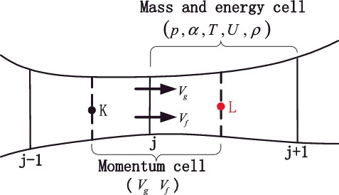
PNCMC uses a staggered mesh shown in , in which the velocities Vg, Vf are defined at the mass and energy cell interfaces and the pressure p, gas volume fraction αg, temperature T, internal energy U and density ρ are defined at the mass, energy cell centers. The difference equations for mass and energy cell are obtained by integrating the mass and energy equations with respect to the spatial variable z, from the junction at zj to zj + 1. The momentum equations are integrated with respect to the spatial variable from cell center zk to adjoining cell center zL.
Figure 3. Schematic of staggered mesh.
Completion of the problem definition requires a choice of two independent variables from the four thermodynamic variables: pressure, temperature, density and specific internal energy. Density is not a good choice because a small error in a solution for density can turn into a significant error in pressure. If pressure is chosen as an independent variable, a small error in the solution for pressure results in an even smaller fractional error in density and temperature. The heat transfer at the interfaces of liquid–gas and fluid–heat structures depends on the temperature differences that must be evaluated implicitly in in the numerical equations. So p, Tf, Tg, αg, Vf, Vg are chosen as independent variables in PNCMC. Under single liquid phase condition (αg ⩽ 1.0− 6), the gas temperature is set as local saturation temperature; and under single gas phase condition (αg ⩾ 0.99999), the liquid temperature is also set as local saturation temperature. When phase change occurs (from single-phase to two-phase) in the control volume, the αg changes first.
Equations of state provide density and internal energy as functions of pressure and temperature. The relationships are generally nonlinear; therefore, Taylor series expansions Equation(18)(18)
(18) –(Equation20
(20)
(20) ) about old time values are used to obtain a linear formulation in the new time variables.
(18)
(18)
(19)
(19)
(20)
(20) where n denotes known values at the current level in time, n + 1 denotes a value at the next level in time, Δt is the increment in time between levels n and n + 1.
To obtain linear difference equations, total interfacial shear force Mdg, wall friction pwαfwτfw and pwαgwτgw are rearranged in new forms:
(21a)
(21a)
(21b)
(21b)
(21c)
(21c)
The semi-implicit, one order up-wind difference scheme is applied to obtain difference EquationEquations (22)(22)
(22) –(Equation27
(27)
(27) ).
The gas continuity difference equation is
(22)
(22)
The liquid continuity difference equation is
(23)
(23)
The gas energy difference equation is
(24)
(24)
The liquid energy difference equation is
(25)
(25)
The gas momentum difference equation is
(26)
(26)
The liquid momentum difference equation is
(27)
(27)
The scalar variable at junction j is defined as
(28)
(28)
The solving technique of above equation group is taken from RELAP5 [Citation15]. Through a series of matrix transformation, we can obtain an N × N system of linear equations for the new time pressures.
(29)
(29)
Successive Over Relaxation (SOR) method is used to solve EquationEquation (29)(29)
(29) and to obtain the new time pressure for each volume. Then, the pressures are substituted in EquationEquations (26
(26)
(26) ) and (Equation27
(27)
(27) ) to obtain the new time velocities. At last, pressures and velocities are substituted in EquationEquations (22
(22)
(22) )–(Equation25
(25)
(25) ) to obtain the new time gas volume fraction and temperatures.
A lumped-parameter solution is available to the user in this basic version to solve the coupling between hydrodynamic volumes and solid structures. And outer iteration is designed to obtain accurate solid temperature. First, we assume a provisional structure temperature Tpw, and substitute Tpwin EquationEquations (24(24)
(24) ) and (Equation25
(25)
(25) ). After solving the difference EquationEquations (22)
(22)
(22) –(Equation27
(27)
(27) ), we substitute Tn + 1g, Tn + 1f in EquationEquation (30)
(30)
(30) to obtain Tn + 1w.
(30)
(30) where N is hydrodynamic volume number connected to structure, and Vi is the volume of hydrodynamic volume.
If the results do not satisfy the convergence criterion |Tn + 1w − Twp| ⩽ 0.01, then we make Tpw = Twn + 1 and repeat above processes. A schematic representation of the algorithm is depicted in .
Figure 4. Algorithm to solve the two-phase flow equations.
5. Code validation
Code validation should cover a broad range of conditions and phenomena. A lot of verifications of PNCMC for stationary problem, such as subcool boiling and Type-I instability in Chinese nuclear heating reactor, have been done in [Citation16]. Since only few natural circulation experiments under motion conditions were performed in previous studies, we don't have enough experiment data for validation. In this study, single-phase natural circulation experiments under rolling conditions performed in INET (Institute of nuclear and new energy technology of Tsinghua University) and two-phase natural circulation experiments under rolling condition performed by Tan et al. are used for the validation of PNCMC.
5.1. Single-phase natural circulation under rolling conditions
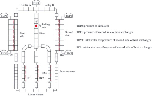
To understand the natural circulation behavior of the integral type reactor under inclination and rolling conditions, a scaled test facility is designed in INET. The test facility is a reactor simulator (natural circulation test loop) mounted on rolling equipment, and shown schematically in . The symmetrically arranged test loop consists of three heating channels (from left to right, HC1, HC2 and HC3), two heat exchangers (HEX_A and HEX_B), a riser section, a nitrogen pressurizer, hot legs (Hot leg A and Hot leg B), lower plenum and connecting pipes. The general configuration of the test loop was determined with reference to NHR-200. The natural circulation flow rate was measured at the outlets of each heating channel and downcomer by ultrasonic flow meters, which have the accuracy of 0.5% over the measured flow rate value. Temperature is measured by thermocouples with accuracy of 1% over the temperature range. The rolling begins from the time that natural circulation reaches steady state under vertical condition.
Figure 5. Schematic of the test facility.
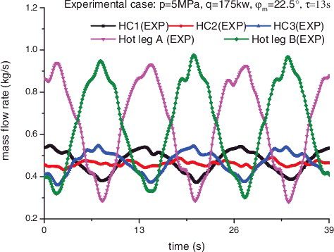
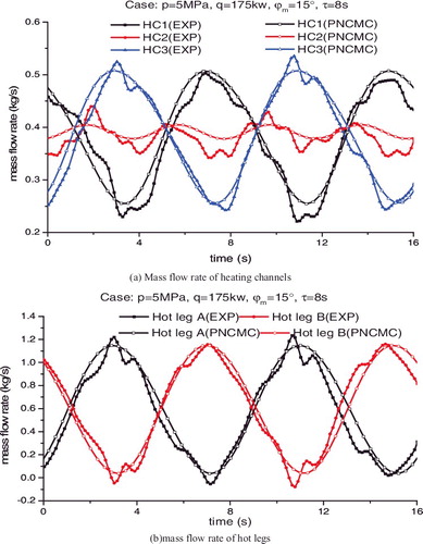
shows the results of one case of natural circulation experiment under rolling condition. As was observed, the heat and flow symmetry between heating channels and hot legs was broken. The mass flow rates of heating channels began to oscillate when the rolling started, the oscillation periods of left and right heating channels were the same as those in rolling motion; however, the oscillation period of middle heating channel was half of the period in rolling motion. The same oscillations were also observed in mass flow rates of hot legs with rolling period; however, oscillation amplitudes were much larger than that of heating channels. The phenomenon was similar to that found by Murata et al. [Citation5].
Figure 6. The result of natural circulation experiment under rolling condition.
The node model for test facility is shown in , and the distance from rolling axis (red point in ) to bottom of test loop is 3.2 m. The coordinates of hydrodynamic volumes’ center and unit vector of main flow stream in the noninertial frame are added when establishing the input card. Boundary conditions of the analysis including the inlet water temperature and the outlet pressure of second side of heat exchangers, and the pressure of simulator were constants. The initial condition of transient simulation corresponds to vertical steady-state. The mass flow rate of second side was kept constant during calculation, which was consistent with experiment.
Figure 7. Nodalization of test facility for PNCMC.
The comparisons between experimental results and PNCMC prediction are shown in and . The comparisons indicated that PNCMC can figure out the variation trend of mass flow rate. The pressure drop coefficients (heating channels and heat exchangers; places of abrupt area change) used in the input card were measured in different power level in vertical steady-state experiments; so there was a small numerical deviation between experiment and PNCMC.
Figure 8. Comparison between experiment results and PNCMC prediction, experiment case: φm = 22.5°, τ = 13 s.
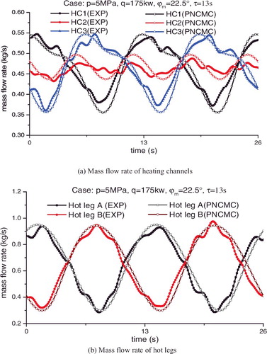
Figure 9 . Comparison between experiment results and PNCMC prediction, experiment case: .
5.2. Two-phase natural circulation under rolling conditions
Tan et al. experimentally studied the two-phase flow instability of natural circulation under rolling motion condition [Citation7]. The test facility is shown in , and is composed of a simple natural circulation loop and a rolling plate. According to the configuration of the test facility, the natural circulation loop was modeled with 56 volumes, as shown in . The detailed local pressure drop coefficients, the length and diameter of pipes, and experiments procedure are not available in [Citation6], which are major influence factors of two-phase natural circulation. Through the incomplete information, it is difficult to simulate accurately of Tan's experiments. So, this validation focused on the repetition of phenomenon, not on numerical accuracy.
Figure 10. Schematic of test facility ( in Tan et al. [Citation7]).
![Figure 10. Schematic of test facility (Figure 2 in Tan et al. [Citation7]).](/cms/asset/37c746d0-397d-4045-9698-d233231750ec/tnst_a_1262295_f0010_oc.jpg)
Figure 11. The nodalization of Tan's test facility for PNCMC.
shows the mass flow rate variation under rolling motion with increasing heating power from 3 to 13 kW. The rolling motion began at 2500 s, and then the mass flow rate oscillated periodically. As the heating power increased, the oscillation amplitude decreased slowly and then enlarged suddenly when the power reached 12.0 kW. indicates that vapor bubbles generated around the trough point of the flow oscillation, and single-phase flow and two-phase flow alternatively appeared in heating pipe, which was also observed in Tan's experiments. This oscillation was similar to density wave oscillation (DWO), but it was not self-excited; the flow would become steady single-phase flow if rolling motion stops. Increasing heating power continuously, the variation of mass flow rate was no longer approximate sine wave. In one rolling period, the mass flow rate increased faster than decreased, and a short-lived increase occurred in the process of decrease marked by arrow in . This irregular complex flow oscillation was a transition process, and the oscillation kept evolving until an overlapping of flow oscillation caused by rolling motion and DWO occurred in . The prediction of PNCMC was consistent with experimental result. In one rolling period, there were three short periodic oscillations from 3.1 to 3.6 s, which was because the period of DWO was about 3 s. As shown in , the overlapping effect was obvious and enhanced the oscillation, and the system became more unstable. To sum up, PNCMC has the ability to simulate two-phase flow under rolling motion.
Figure 12. Mass flow rate variation under rolling motion.
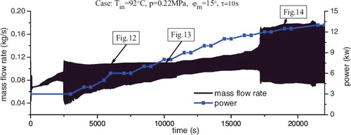
Figure 13. Mass flow rate variation at heating power equals to 6.0 kW.
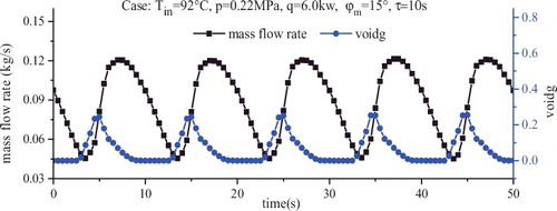
Figure 14. Irregular complex flow oscillation.
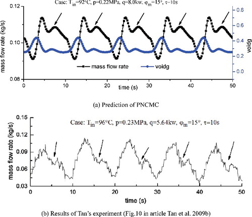
Figure 15. Overlapping of flow oscillation caused by rolling motion and density wave oscillation.
6. Conclusions
In the present work, one-dimensional two-fluid model in noninertial frame of reference is proposed. The body force term in the momentum equation is modified as time dependent function and inertial force induced by ship's three-dimensional motion, such as rolling, heaving and inclination are added into this term. The constitutive relations including models for defining flow regimes and flow regime-related models for total interfacial shear force, wall friction, wall heat transfer and interphase heat transfer are in accordance with that used in RELAP5/MOD3.3. Staggered mesh, finite volume method, semi-implicit first order upwind scheme, lumped-parameter solution of heat structures and SOR method are used to discretize and solve two-phase mass, momentum and energy equations. PNCMC code is developed based on these difference equations and compiled using C++ language.
Single-phase natural circulation experiments under rolling conditions performed in INET and two-phase natural circulation experiments under rolling condition performed by Tan et al. are used for the validation of PNCMC. The calculation results are in good agreement with single-phase experiments. PNCMC can figure out the phenomenon that was found in two-phase experiments. However, much more two-phase natural circulation experiments are needed to evaluate the accuracy of PNCMC.
| Nomenclature | ||
| A | = | Area of cross section (m2) |
| a0 | = | Acceleration of noninertial frame relative to stationary frame (m/s2) |
| Cp | = | Specific heat at constant pressure (J/kg · K) |
| FI | = | Interphase drag coefficients (liquid, vapor) (s−1) |
| FWF, FWG | = | Wall drag coefficients (liquid, vapor) (s−1) |
| fine | = | Extra acceleration (m/s2) |
| g | = | Gravity acceleration (−9.8 m/s2) |
| Hif | = | Volumetric heat transfer coefficient from interface to liquid (W/K · m3) |
| Hig | = | Volumetric heat transfer coefficient from interface to gas (W/K · m3) |
| HLoss | = | Pressure drop (Pa) |
| h | = | Enthalpy (J/kg) |
| Hwf | = | volumetric wall heat transfer coefficient for liquid (W/Km3) |
| Hwg | = | volumetric wall heat transfer coefficient for gas (W/Km3) |
| Mdg | = | Total interfacial force (N) |
| m | = | Mass (kg) |
| P | = | Pressure (Pa) |
| pw | = | Channel perimeter (m) |
| q | = | Heating power (w) |
| q''' | = | Power source (w/m3) |
| r | = | Radial vector of fluid particle in noninertial frame (m) |
| T | = | Temperature (K) |
| t | = | Time (s) |
| U | = | Specific internal energy (J/kg) |
| V | = | Velocity in noninertial frame (m/s), volume (m3) |
| x, y, z | = | Spatial coordinate (m) |
| Greek letters | = |
|
| α | = | Gas volume fraction |
| αgw | = | Gas volume fraction near wall |
| αfw | = | liquid volume fraction near wall |
| ζh | = | heating perimeter (m) |
| ρ | = | Density (kg/m3) |
| Γwg | = | Volumetric mass exchange rate near wall (kg/m3 · s) |
| φ | = | Rolling angle (rad) |
| ω | = | Angle velocity of noninertial frame (rad/s) |
| τ | = | Shear stresses (N), rolling period (s) |
| = | Angle acceleration of noninertial frame (rad/s2) | |
| ϖd | = | Rolling frequency of noninertial frame (Hz) |
| Subscripts | = |
|
| f | = | Liquid phase |
| g | = | Gas phase |
| j | = | Spatial noding indices for junctions |
| K | = | Spatial noding index for volumes |
| L | = | Spatial noding index for volumes |
| k | = | k = f or k = g |
| m | = | Maximum |
| i | = | Two-phase interface |
| s | = | Saturation state, heat structure |
| sf | = | Saturation state of liquid |
| sg | = | Saturation state of gas |
| w | = | Pipe wall |
| z | = | Main stream |
| Superscripts | = |
|
| n, n + 1 | = | Time level index |
| • | = | Donored quantity |
| * | = | Bulk/saturation property |
Disclosure statement
No potential conflict of interest was reported by the authors.
Additional information
Funding
References
- International Atomic Energy Agency. Status of small and medium sized reactor designs. Vienna: IAEA; 2011.
- Zhong J, Yang XT, Jiang SY. The overview of natural circulation characteristics of a marine reactor under ocean condition. 17th International Conference on Nuclear Engineering; 2009, July 12–16; Brussels, Belgium.
- Ishida T, Kunsunoki T. Effect of ship motion on the reactor system: experimental voyage of nuclear powered ship MUTSU. Paper presented at: International Conference on New Trends in Nuclear System Thermal-Hydraulics; 1994; Pisa, Italy.
- Ishida T, Yao T, Teshima N. Experiments of two-phase flow dynamics of marine reactor behavior under heaving motion. J Nucl Sci Technol. 1997;34(8):771–782.
- Murata H, Sawada H, Kobayashi M. Natural circulation behaviors of a marine reactor in rolling motion and heat transfer in the core. Nucl Eng Des. 2002;215:69–85.
- Tan SC, Su GH, Gao PZ. Experimental and theoretical study on single-phase natural circulation flow and heat transfer under rolling motion condition. Appl Thermal Eng. 2009;29:3160–3168.
- Tan SC, Su GH, Gao PZ. Experimental study on two-phase flow instability of natural circulation under rolling motion condition. Ann Nucl Energy. 2009;36:103–113.
- Yan BH, Yu L. The experimental and theoretical analysis of a natural circulation systems in rolling motion. Prog Nucl Energy. 2012;54:123–131.
- Gao PG, Pang FG, Wang ZX. Mathematical model of primary coolant in nuclear power plant influenced by ocean conditions. Chin J Harbin Eng Univ. 1997;18(1):24–27.
- Guo Y, Qiu SZ, Su GH, et al. The influence of ocean conditions on two-phase flow instability in a parallel multi-channel system. Ann Nucl Energy. 2008;35:1598–1605.
- Yan BH, Yu L. The development and validation of a thermal hydraulic code in rolling motion. Ann Nucl Energy. 2011;38:1728–1736.
- Ishida T, Yoritsune T. Effects of ship motions on natural circulation of deep sea research reactor DRX. Nucl Eng Des. 2002;215:51–67.
- Kim JH, Park GC. Developemt of RETRAN-03/MOV code for thermal hydraulic analysis of nuclear reactor under moving conditions. J Korean Nucl Soc. 1996;28(6):542–550.
- Ishii M, Mishima K. Two fluid model and hydrodynamic constitutive relations. Nucl Eng Des. 1984;82:107–126.
- RELAP5 Development Team. RELAP5/Mod3 Code Manual. Vol. 4. NRC: NUREG/CR-5535; 1995.
- Gong H. Research on the two-phase natural circulation characteristics and density wave instability under ocean conditions [thesis]. Beijing: Tsinghua University; 2014.