
 ?Mathematical formulae have been encoded as MathML and are displayed in this HTML version using MathJax in order to improve their display. Uncheck the box to turn MathJax off. This feature requires Javascript. Click on a formula to zoom.
ABSTRACT
The swim-type remotely operated vehicle (ROV) for inspection of narrow spaces in nuclear power plants has been developed. Many structures are crowded in a confined space at regular intervals in the bottom area of a reactor. So, the thickness of the ROV shape is an important design point to ensure that the ROV can move in the space. The developed ROV has a three-dimensional swimming mechanism using six thrusters, three cameras for observing the position while moving and for making inspections easily, and a localization system. The localization system combines two elements: a gyroscope to detect the progression direction; and a slit laser that detects the progression distance using the optical cutting method. The localization method is called the modified inertial navigation (MIN) method and it was evaluated in a mock-up examination. The ROV was able to move smoothly using the MIN method and its position could be detected without making a mistake in the route followed.
1. Introduction
In nuclear power plants, it is important that the integrity of their nuclear reactors is inspected regularly. This paper considers the inspections in the nuclear reactors of boiling water reactor (BWR) plants. There are a lot of check points in the periodic inspection, and the state of structures in the nuclear reactors is inspected by various methods including visual testing (VT), ultrasonic testing, eddy current testing, and penetration testing [Citation1]. At the same time, some equipment were developed to carry out these testing methods for periodic inspection of the reactor pressure vessel (RPV) [Citation2]. In particular, inspections are made for the welds between structures and the welds of piping carrying high-pressure fluids. Then this paper targets the welds found in the bottom area of the RPV in a water depth of 30 m. Because the inside of the RPV has many narrow spaces, and there are many structures, remotely operated vehicles (ROVs) are convenient for inspection [Citation3]. ROVs are often used in a marine environment [Citation4], but it is necessary to downsize them so that they can be applied in limited narrow spaces [Citation5] like the bottom area of the RPV [Citation6,Citation7].
The position of the ROVs used for inspections in normal nuclear reactors is estimated from images taken by cameras mounted on the ROVs or by underwater cameras. However, in the bottom of the RPV where there are many structures of the same shape at regular intervals, it is easy to misjudge the position, so it is important to have an accurate position estimation technology. This paper describes the development of a visual inspection device (i.e. a VT device) for the bottom area of BWRs. It is a small swim-type ROV with a self-localization estimation function.
2. Development and design of the swim-type ROV for narrow space inspection
2.1. Application target and development purpose
shows a schematic structure of the BWR. The RPV is filled with water, and fuel assemblies are placed inside the shroud. In the bottom of the RPV, the fuel assemblies, the control rod drive mechanism (CRD) housings and the CRD stub tubes are located at regular intervals, so there are many complicated narrow spaces. The CRD stub tubes are fixed to the RPV by welding. The ROV developed in this paper is to be used to inspect weld parts in the bottom of the RPV. Therefore, this ROV must be able to move in these narrow spaces and it must have a camera system that acquires clear pictures. Cables are used to provide the power supply and transmit signals to the ROV. Cables are necessary to avoid the chance that the ROV would not have enough power to return after the inspection tasks and because wireless communication is difficult underwater. This study focused on developing the movable ROV that could pull cables while traveling in the narrow spaces of the bottom part of the RPV, and that could provide clear pictures when making inspections.
Figure 1. Structure of a BWR.
2.2. Design of ROV
2.2.1. Required specifications
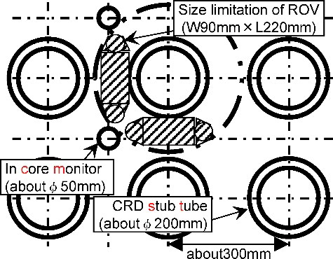
explains the inspection target area and size limitation of the ROV. The CRD stub tubes of approximately 200 mm in diameter are regularly arranged approximately every 300 mm. In addition, within the CRD stub tube grouping, there are several in-core monitor (ICM) housings of approximately 50 mm in diameter. For the ROV to move within these size spaces, so that all the welds can be inspected, it must be no more than 90 mm in width and 220 mm in length.
Figure 2. Horizontal section of the paths in the bottom area of a reactor and ROV size limitation.
In addition, so that VT of the narrow spaces is carried out, it is necessary that the ROV have all-around movement, up and down movements, turning without changing its posture, and tilting and panning of the ROV-mounted camera. Furthermore, the ROV cannot become caught on a structure as it moves between the narrow spaces while pulling its cables. Generally, a neutral buoyancy cable is used for the ROV cables, but the neutral buoyancy cable is rigid which inhibits moving performance. Therefore, cables with a flexible portion, approximately 1 m long, are connected to the body of ROV. But because the flexible section has a risk of becoming caught on a structure, the ROV is designed to move while checking the cable status using a backward-facing camera. Furthermore, to ensure VT position confirmation, a self-localization function of the ROV is necessary. lists the required specifications of the ROV.
Table 1. Specifications of ROV.
2.2.2. Shape and constitution
shows the structure of the ROV designed with the required specifications given in Section 2.2.1 and . In particular, for checking between the CRD stub tube and the ICM housing, the ROV is set to 80 mm in width and 211 mm in length. It has a height of just 345 mm because its parts are arranged in a closely packed structure. Movement is done by six thruster units; four are for vertical movement and two are for horizontal movement. Furthermore, a camera and an LED are located in the lower part for VT, and two cameras and an LED are installed to observe back and forth movements.
Figure 3. Detailed structure of ROV. Six thrusters and three cameras are installed (unit: mm).
2.2.3. Movement mechanism
shows details of the placement and movement patterns of the thrusters. The four thrusters for the vertical movement are all located in the same plane and they are inclined 45 degrees from the horizontal plane. When the connection point of the cables is assumed to be at the rear of the ROV, these four vertical movement thrusters push the water backward to get forward movement as shown in (a). On the other hand, the ROV moves in reverse if the water is pushed forward. The ROV rises when the four vertical movement thrusters push the water downward, and the ROV drops when the water is pushed up as seen in (b). Furthermore, the ROV moves horizontally without changing its posture and it is pressed to an object when two vertical movement thrusters are pointing in the same direction as seen in (c). Finally, the ROV rolls when two vertical movement thrusters are pointed in opposite directions as seen in (d). In addition, the ROV is controlled according to an instruction manual for periodic inspection, so it does not need constant supervision such as detailed viewing or re-routing of the check points based on the VT results.
Figure 4. Placement of the thrusters. The water current direction of the thrusters for (a) moving forward, (b) rising, (c) pressing to an object, and (d) rolling.
2.2.4. Cameras
(a) shows camera positions on the ROV. The two cameras for observing forward and backward movements have a fixed wide angle and fixed focus lens. In addition, a third camera for VT is located in the lower part of the ROV. This camera has a remote focus and a panning and tilting mechanism. (b) shows a target image for VT. At the time of VT, two horizontal movement thrusters are used to press the ROV to the inspection target; for example, when pressed to the CRD stub tube, the pan and tilt mechanism of the camera for VT is operated and a detailed picture of the weld is acquired.
Figure 5. (a) Camera positions and (b) a target image of VT.
3. Inertial navigation style localization method
3.1. Summary of the inertial navigation style localization method
For methods to localize underwater mobile equipment, one example is a method [Citation8] to estimate the position by an image correlation of the pattern of the bottom surface and another example is an inertial navigation style [Citation9] localization method that can be used when an inertial force is big because the moving speed is fast. However, this second method is not applicable for the present ROV because the moving speed is slow. Therefore, a new combination method shown in was suggested and examined. This is an inertial navigation localization method that is suitable for narrow spaces and it is called a modified inertial navigation (MIN) method. At first, from a camera image, a moving quantity is calculated by the inertial navigation method using the optical cutting method [Citation10] and a position correction method. Then the posture of the camera is corrected using the rotation angle detected by a gyroscope. Next, from the rotation angle and moving quantity, a relative position is calculated, starting point information is added, and an absolute position is calculated. In addition, from map matching [Citation11], an interference judgment for a structure is carried out after the localization, and the previous position is used when there is interference. Furthermore, within the visible range of the underwater stereo camera, the absolute position is revised by a position calculated by the stereo method [Citation12].
Figure 6. MIN method for localization of ROV for narrow space inspection.
3.2. Progression distance detection by the optical cutting method
3.2.1. Distance detection by the optical cutting method
explains the optical cutting method. A horizontal slit laser beam is emitted in the forward direction by a laser light source installed parallel to the camera for movement. The image of the object which the laser light hits is captured, and the number of the pixels B from the longitudinal center of the image to the laser image is detected. B is substituted into EquationEquation (1)(1)
(1) , and distance L to the object is calculated. Here, for the distance between the optical axis of the laser light source and the camera axis, which is d, and the vertical angle of the field of the camera, which is α, the half number of the vertical pixels of the image is assumed to be A.
(1)
(1)
Figure 7. Principle to determine distance by the optical cutting method. The image of the object which the emitted laser light has captured and the distance from the camera to the object which is calculated by the pixel number of the laser image.
It is assumed that the camera axis is completely parallel to the laser light source in EquationEquation (1)(1)
(1) , but in reality, it is often slightly declined when installed. Therefore, distance L is as given in EquationEquation (2)
(2)
(2) when the degree of declining δα is considered. In addition, it is necessary for this degree of declining δα to be measured by a prior calibration.
(2)
(2)
3.2.2. Progression distance detection algorithm
shows the procedure for calculation of the ROV progression distance from the distance to an object detected by the optical cutting method explained in Section 3.2.1. After capturing the image, the distortion due to the wide-angle lens is corrected. The threshold set by the density distribution is used and the image is binarized. Because the result becomes discrete, as shown in , one target image is coupled to one domain by dilation processing. Then, it is made linear by erosion processing, and laser images are extracted. The extracted laser images are classified to every object by a cluster analysis. This cluster analysis is a method to classify all target points in the group of a pre-determined number, and there are several known calculation methods. In this paper, the median method suitable for clustering of the linear distribution point group was considered to be the basic method. Furthermore, for the purpose of vertical discrimination improvement of the images, the modified median method in which the vertical calculation distance was considered to be several times the lateral calculation distance was devised originally. After clustering, the speed according to the cluster is calculated for difference between two position of consecutive times of the same cluster. In addition, the most distant visible point in each cluster, namely the laser image point at the central or near the center, is used as shown in for an inner cluster representative distance calculation point. The reason is that it is necessary for the same point to be used for the distance calculation regardless of the size of the cluster, and the most distant visible point has little influence from the posture of the camera because it is stable and it is a detected distance. shows a calculation example. (a) is a distance calculation example for six clusters. In this figure, for example, the distance greatly changes at about 2 s in cluster 1 and cluster 2, and at about 12 s in other clusters than 1; this is because the object which the laser beam hit has changed. When an object changes ((b)), speed calculated by the difference shown in (a) changes more than 0.02 m/s. In addition, it is necessary to set the value just before the biggest driving force of the thruster is changed because this value must be set to the maximum velocity of the ROV. Then, moving speed of the ROV is calculated from the speed calculated according to a cluster. Speed V2 of cluster 2 is adopted when speed V1 of cluster 1 is set as shown in , and when V1 exceeds 0.02 m/s and V2 exceeds 0.02 m/s, speed V3 of cluster 3 is adopted sequentially. Using this procedure prevents a ‘jump’ of the speed calculation, when the object which the laser beam hits changes. (c) shows estimated velocity calculated by the algorithm of . In addition, (d) shows the calculated progression distance (moving distance calculated as integral of (c)).
Figure 8. Algorithm to detect progression distance. The algorithm calculates the ROV progression distance from the distance to an object detected by the optical cutting method.
Figure 9. Results of binarization. (a) Distortion correction, (b) binarization, and (c) dilation process.
Figure 10. Image for clustering. The most distant visible point in each cluster which is at or near the center is representative distance calculation point.
Figure 11. Example results for calculation of the progression distance. (a) Distance calculation example for six clusters; (b) relative velocity; (c) estimated velocity; and (d) progression distance calculated by the algorithm of .
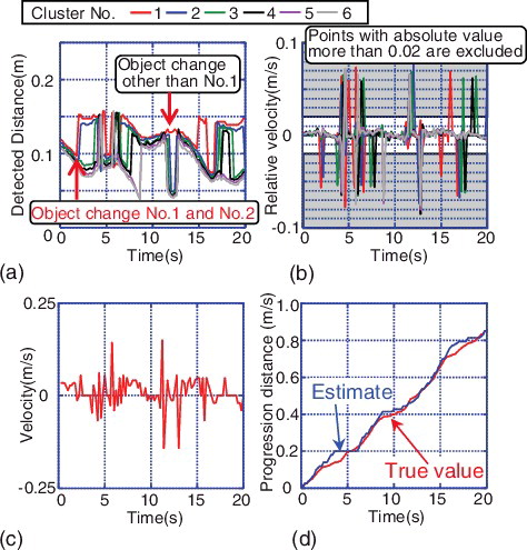
In (d), the blue line shows moving distance calculated by the algorithm and the red line shows moving distance detected by a position tracking system using the epipolar projections [Citation13]. For the movement of approximately 1 m, the moving distance was detected with an error of approximately 0.05 m.
3.2.3. Progression direction detection with the inertial sensor
Because there are various types of detection principles for gyros [Citation14], signal processing is different for each. In addition, there are various sizes of gyros; the ceramic gyro, which is the smallest commercial type, was used for the ROV in this paper. The ceramic gyro outputs the voltage proportional to angular acceleration at the time of a turn. However, because the standard voltage of the gyro fluctuates, between the root mean square (RMS) as the actual value of several seconds, the RMS of the period with a small change is set for the standard voltage. In this study, this method is named the shift RMS method. EquationEquation (3)(3)
(3) shows the angle of rotation calculated from the gyro output using the shift RMS method.
(3)
(3)
Expression (Equation3(3)
(3) ) is an example that assumes a time period of 6 s around t. Function F means that the smallest value is adopted for the standard voltage in the actual value of 6 s. Δθ is the change value of the rotation angle, T is the current time, ΔT is an update interval between the amount of change, G(t) is the gyro output at t, Grms(a,b) is RMS of G between a and b, and F{a1, a2, a3, …, an} is a macro function to choose the minimum RMS of the time difference between {a1, a2, a3, …, an}. shows an example of the shift RMS method: (a) shows the output of the gyro and results of the shift RMS, and (b) shows the results when the angle of rotation was calculated. An examination for the entire circumference of the CRD stub tube was assumed, and the ROV went around it in approximately 3 min. Error after passing 360˚ was less than 10%, and it was confirmed that the angle of rotation was detected reliably.
Figure 12. Example results of shift RMS method. (a) The output of the gyro and results of the shift RMS method. (b) Results when the shift RMS was integrated and angle of rotation was calculated.
3.2.4. Position correction by interference judgment
In the modified MIN method shown in Section 3.1, the position in the self-localization method is calculated by the distance to move relatively from the base position, so it is necessary to correct for the accumulation error of localization. For a correction method, electric waves such as of a GPS system or a cell phone are generally used. However, the electric wave method cannot be used in a reactor. Therefore, the position correction method by interference judgment with three-dimensional computer aided design (CAD) data was considered. shows the concept of the position correction method. The radius of the CRD housing or the CRD stub tube is R, the equivalent radius of the ROV is r, and the distance between their centers is D. The equivalent radius is a virtual radius determined for convenience and it is the radius of the circle touching the ROV housing internally. This was defined for the following reasons, the interference judgment for the complicated shape might be inaccurate and the purpose of making a correction for the interference judgment method is to ensure that a structure is not penetrated in the inspection area. In , the ROV at position A was assumed to move to position B. It was assumed that an error occurred then for the progression direction and it was changed to position B' circumscribed for the CRD housing or the CRD stub tube. In this method, an error can occur easily in the direction with the gyro, so that when distance is corrected in the interference judgment method, there is no convergence. For these reasons, the calculation error of the distance was not corrected.
Figure 13. Concept of the position correction method. The position A is moved to position B. An error occurred in the progression direction and position B was changed to position B'.
3.2.5. Position correction with the underwater stereo camera
Because position is never corrected in the self-localization method shown here, position correction is difficult if the error becomes big. Therefore, an underwater stereo camera is used, and the absolute position is corrected. shows the principle of the position decision by the stereo method. EquationEquation (4)(4)
(4) shows the coordinates (x, y, and z) of the target where the distance of the camera is L, the distance between the projection center and the image side is f, and the image side coordinates of the target in the right image are PR(uR, v) and the left image are PL(uL, v).
(4)
(4)
Figure 14. The principle of the position decision by the stereo method.
Position of the ROV is calculated by this principle. Because the ROV must be contained in the field of vision of the two cameras in the stereo method, there is a limitation in the area with many structures. Therefore, in the MIN method, better position information is possible for the procedure shown in . At first, a position is absolutely detected by the inertial navigation method. The calculation position using the stereo cameras becomes the position of the ROV if the ROV is in the field of vision of the stereo cameras. In addition, only inertial navigation and the correction by the interference judgment of the structure are carried out when the ROV is out of the field of vision of the cameras.
Figure 15. The position correction procedure in the MIN method. Correction was made in the field of vision of the stereo camera by the stereo method and any additional correction was made by an interference judgment.
4. Performance evaluation results
4.1. Summary of the performance evaluation examination
The performance of self-localization by the MIN method shown in Section 3.1 was confirmed. The examination was carried out using the mock-up shown in (a). This mock-up simulated a partial structure of the actual BWR plant shown in (b).
Figure 16. (a) The structure of the mock-up for the examination and (b) the structure of the actual BWR plant.
shows the setup for the mock-up examination. Water was filled to the top of the CRD housing, and the ROV was controlled while viewing it from the outside stereo camera. The ROV position was followed by the outside stereo camera, and a three-dimensional position was calculated. The cables from the ROV were connected to the ROV control unit, and the movie images and the gyro signal were output to the PC. Two controllers (one for the ROV control and one for the VT camera operation) were connected to the control unit.
Figure 17. Setup for the mock-up examination. The ROV position was tracked by the outside stereo camera and the position was calculated three-dimensionally.
shows the moving path in the examination. These are four representative operations for inspection of the bottom area of a nuclear reactor. (a) shows forward and backward moving, (b) shows circular movement simulating continuous inspection of the CRD circumference, (c) shows alternating movement by turning right and left, and (d) shows a series of inspection tasks by circular moving. The target in this mock-up examination was the CRD stub tube and it was checked whether the pictures taken by the camera put on the ROV could identify the tube. Therefore, the tolerance of the self-localization was less than 0.15 m, that is, half of the distance between CRD stub tubes. shows the placement of the underwater stereo camera. An actual inspection was assumed, and the field of vision of the underwater stereo camera was limited to the straight line domain.
Figure 18. These are four representative operations for inspection of the bottom area of a nuclear reactor.
Figure 19. Placement of the underwater stereo camera.
4.2. Performance evaluation examination
shows an image of the performance evaluation examination. The photo gives the tracking results for an example image from the outside stereo camera for ROV positioning. The light from the LED on the top of the ROV was caught by the outside stereo camera, and the position of the ROV was calculated. In addition, the underwater stereo camera caught the light of the LEDs attached to the front and back of the ROV that were used for position correction.
Figure 20. The performance evaluation examination.
4.3. Performance evaluation examination
4.3.1. Forward and backward movements
shows localization results of the forward and backward movements. (a) shows the tracking results by the outside stereo camera. (b) shows the results of the localization by the MIN method. (c) shows the results when the error of the MIN method was evaluated for the differences between (a) and (b). The ROV started from the left edge of (a) and repeated movements to turn at the right side and return to the original position three times. In this case, because the ROV was always in the field of vision of the underwater stereo camera, its position was corrected and could be estimated at the target error of less than 0.15 m. In addition, at the progression distance of approximately 3.5 m, the error became big. The reason was that the LEDs of the ROV were not caught by the underwater stereo camera when the ROV turned to the side.
Figure 21. Localization error by MIN method in forward and backward movements. (a) Results of localization by the outside stereo camera. (b) Results of localization by the MIN method. (c) Results of the localization error.
4.3.2. Circular movement
shows the examination results of the circular movement. The ROV went around the CRD housing six times. That the ROV had gone completely around the structure was captured definitely by (b). But, for this case, there were many spaces that were not corrected by the underwater camera. As a result, it is confirmed that position precision decreases to 0.2 m as (c) shows it. In addition, the error did not accumulate because it was corrected even if the estimated precision dropped when the ROV entered the field of vision of the underwater stereo camera.
Figure 22. Localization error by MIN method in circular movement. (a) Results of localization by the outside stereo camera. (b) Results of localization by the MIN method. (c) Results of the localization error.
4.3.3. Right and left turning movements
shows test results for the turning movements right and left. The tendency was similar to that in and , in the straight line area of the underwater camera field of vision including the start point, the ROV position was estimated reliably by the correction. But the error grew big and was approximately 0.3 m in the space where the ROV did not enter the field of vision of the underwater stereo camera.
Figure 23. Localization error by MIN method in right and left turn movements. (a) Results of localization by the outside stereo camera. (b) Results of localization by the MIN method. (c) Results of the localization error.
4.3.4. Visual testing simulated movement
shows the results when VT movement was assumed and the ROV moved around a structure. Again, the tendency was similar to the other cases, for example, precision for correction was low, and an error of up to approximately 0.2 m occurred because the ROV did not enter the field of vision of the underwater stereo camera at the red triangle positions in (b,c). On the other hand, the position was estimated reliably within 0.15 m when the ROV was in the field of vision of the underwater stereo camera.
Figure 24. Localization error by MIN method in simulated VT. (a) Results of localization by the outside stereo camera. (b) Results of localization by the MIN method. (c) Results of the localization error.
5. Conclusion
The new swim-type ROV for inspections of narrow spaces in nuclear power plants has been developed. This paper examined the ROV structure and its localization system. The developed ROV was a thin shape with a thickness of 90 mm. It had a three-dimensional swimming mechanism using six thrusters, three cameras for observing the position while moving and for making inspections easily, and a localization system. Moreover, the localization system combined two elements: a gyroscope for detection of the progression direction and a slit laser to detect the progression distance using the optical cutting method. This method was called the MIN method. The ROV and the MIN method were evaluated by the mock-up examination. The ROV could move smoothly, and its position could be detected without making a mistake in the route.
Disclosure statement
No potential conflict of interest was reported by the authors.
References
- Odakura M, Kometani Y, Koike M, et al. Advanced inspection technologies for nuclear power plants. Hitachi Rev. 2009;58(2):82–87.
- Chmelik V, Engl G. Ultrasonic inspections of reactor pressure vessels in Slovakia. Proceedings of 15th World Conference on Nondestructive Testing; 2009 Oct 15–21; Roma, Italy.
- Takatori Y, Otani K, Kimura K, et al. Development of underwater vehicle system for reactor internals inspection. Proceedings of the 7th International Conference on NDE in Relation to Structural Integrity for Nuclear and Pressurized Components; 2009 May 12–14; Yokohama, Japan. p. 828–835.
- Ura T. Development of autonomous underwater vehicles in Japan. Adv Robot. 2002;16(1):3–15.
- Ito T. Repair technology of the structure in a reactor of BWR plant. Maintenology. 2009;22(6):19–24. Japanese.
- Okada S, Kobayashi R, Tooma M, et al. Development of the tandem underwater vehicle system for narrow space inspections. Proceedings of the 7th International Conference on NDE in Relation to Structural Integrity for Nuclear and Pressurized Components; 2009 May 12–14; Yokohama, Japan. p. 437–444.
- Yuguchi Y, Shimamura M, Kimura M. Advanced inspection technologies for nuclear power plants. Toshiba Rev. 2002;57(8):60–63.
- Kondo H, Maki T, Ura T, et al. A structure observation system with an autonomous underwater vehicle: relative navigation using a ranging system based on the light-section method. Proceedings of the JSME Conference on Robotics and Mechatronics; 2004. p. 114–115. Japanese.
- Li K, Lingyun Y, Kaichen S. A fast in-situ SINS and Doppler sensor calibration algorithm for underwater vehicle navigation. IEICE Electron Express. 2014;11(23):994.
- Tsukada T. The development of 3D vision sensor for gap and step measurement. Inst Electr Eng Japan. 2013;11(30):1–5. Japanese.
- Liu YH. Constructing an approximate representation of a configure operation space without using an intersection check. Proceedings of the 1993 IEEE/RSJ International Conference on Intelligent Robots and Systems; 1993 July 26–30; Yokohama, Japan. p. 644.
- Zhang Z, Faugeras O. 3D dynamic scene analysis. Springer Series in Information Science. Berlin: Springer Berlin Heidelberg; 1992.
- Hartley R, Gupta R. Computing matched-epipolar projections. Comput Vis Pattern Recognit. 1993.
- Tuzlukov VP. Signal detection theory. New York (NY): Springer Science Business Media; 2001.