 ?Mathematical formulae have been encoded as MathML and are displayed in this HTML version using MathJax in order to improve their display. Uncheck the box to turn MathJax off. This feature requires Javascript. Click on a formula to zoom.
ABSTRACT
Thoughtful consideration of abnormal events such as fire is required to design and qualify a detritiation system (DS) of a nuclear fusion facility. Since conversion of tritium to tritiated vapor over catalyst is the key process of the DS, it is indispensable to evaluate the effect of excess moisture and hydrocarbons produced by combustion of cables on tritium conversion rate considering fire events. We conducted demonstration tests on tritium conversion under the following representative conditions: (I) leakage of tritium, (II) leakage of tritium plus moisture, and (III) leakage of tritium plus hydrocarbons. Detritiation behavior in the simulated room was assessed, and the amount of catalyst to fulfill the requirement on tritium conversion rate was evaluated. The dominant parameters for detritiation are the concentration of hydrogen in air and catalyst temperature. The tritium in the simulated room was decreased for condition (I) following ventilation theory. An initial reduction in conversion rate was measured for condition (II). To recover the reduction smoothly, it is suggested to optimize the power of preheater. An increase in catalyst temperature by heat of reaction of hydrocarbon combustion was evaluated for condition (III). The heat balance of catalytic reactor is a point to be carefully investigated to avoid runaway of catalyst temperature.
1. Introduction
A large amount of tritium will be continuously processed in the future nuclear fusion demonstration reactor (DEMO), which is under planning in Japan [Citation1]. In order to achieve public acceptance of DEMO, technical reliability of tritium confinement shall be required taking hypothetic extraordinary situations such as an event of fire fully into consideration [Citation2]. Detritiation system (DS) is required to remove tritium in any extraordinary situations. DS consists of catalytic reactors to oxidize tritium and removal systems for tritiated water vapor [Citation3]. In the catalytic reactors, gaseous tritium is oxidized to form tritiated water vapor. The tritiated water vapor was removed by a tritiated water removal system, where molecular sieves dryer beds have been used for the existing tritium handling facilities [Citation3] or wet scrubber columns will be applied for ITER [Citation4]. In considering extraordinary situations, the influence of chemical components produced in those situations on detritiation performance shall be carefully investigated. Concerning tritium oxidation by catalytic reactor, poisoning effect by the chemical components still remains an open research problem [Citation5,Citation6].
A well-considered fire protection will be conducted in the DEMO facility. There is less possibility of an event of fire where excess hydrocarbon and moisture generate by combusting polymeric insulation of electrical cables in cable tray for example. However catalytic reactors of DS should be designed to fulfill the requirements of tritium conversion taking possible fire events fully into consideration. Generally, DS in existing tritium handling facilities has two kinds of catalytic reactors [Citation3]. One is a low-temperature reactor (LTR) to oxidize gaseous tritium was oxidized at a temperature around 473 K. The other is a high-temperature reactor (HTR) to oxidize tritiated methane at a temperature around 773 K [Citation7]. The combination of LTR and HTR has been applied in the existing tritium facilities for all normal conditions where concentrations of tritium and tritiated methane to be processed were quite low. The previous research concerning conversion rate of tritium at abnormal conditions is limited [Citation8,Citation9]. At an abnormal condition where excess methane produced from the combustion of polymeric insulation should be processed, HTR will induce sudden increase in temperature by heat of reaction. This increase would become a trigger for another fire-initiating mechanism. Part of tritium would permeate through the high-temperature surface of catalytic reactor. In order to avoid the potential risks of HTR application, we have proposed to process fire gas accompanied with tritium by LTR alone through the supporting evidence by experiments [Citation6]. The experiments showed that reaction to produce tritiated methane between methane and tritiated hydroxyls on catalyst surface will be suppressed by hydrophobic catalyst. It is known that halogenated components poison the catalyst. Hence zero halogen cable should be applied to DEMO. The main components from burned zero halogen cable are methane, ethylene and propylene with excess moisture [Citation10]. We have already confirmed that LTR can combust ethylene and propylene completely. It is known the moisture lower the catalytic activity of hydrophilic catalyst [Citation11]. However, it has been demonstrated the moisture negligibly affects the catalytic activity of hydrophobic catalyst [Citation12].
Our previous research mentioned above had focused on kinetics at the steady state mainly from reaction engineering point of view. Beyond that, dynamic behavior of detritiation under each simulated abnormal event is equally important to validate DS design. The amount of catalyst to fulfill the requirement on conversion rate can be evaluated through the demonstrations. Hence a large leak-tight vessel was prepared as a simulated room, then the conceptual DS module was connected with the vessel to evaluate the change in conversion rate of tritium under the factorized fire scenarios: (I) leakage of tritium, (II) leakage of tritium plus excess moisture, and (III) leakage of tritium plus excess hydrocarbons.
2. Experimental
2.1. Three test conditions to analyze the effect of moisture and hydrocarbons on conversion rate of tritium
In an event of fire, both moisture and hydrocarbons will affect conversion rate of tritium. In order to understand what the dominant condition is, we conducted the test with three different conditions. Scenario (I) was to demonstrate detritiation behavior in case of an accidental leakage of tritium in the absence of both moisture and hydrocarbons. The concentration of moisture in the simulated room was intentionally controlled to be lower than 100 ppm in order to cancel the effect of moisture on tritium oxidation in the catalytic reactor. Scenario (II) was to demonstrate detritiation behavior in case of an accidental leakage of tritium plus excess moisture. We compared the detritiation behavior of Scenario (II) with that of Scenario (I) to evaluate the effect of moisture on conversion rate of tritium. It is generally known that moisture lowers conversion rate of tritium since moisture covers active sites of catalyst by forming water layer [Citation11,Citation13]. Hence, the excess moisture is one of the worst conditions for oxidation of tritium over catalyst. To overcome the well-known moisture effect, we applied the hydrophobic catalyst named TKK-H1P for this test [Citation12]. Scenario (III) was to demonstrate detritiation behavior in case of an accidental leakage of tritium plus excess hydrocarbons. Since the combustion of hydrocarbons produced moisture, Scenario (III) strictly demonstrated an accidental leakage of tritium plus excess moisture and hydrocarbons. We compared the detritiation behavior of Scenario (III) with that of Scenario (II) to evaluate the effect of hydrocarbons on conversion rate of tritium. The main fire load is considered as polymeric insulation of electrical cables. Halogenated cables will be prohibited due to the poisoning effect of halogenated components on catalytic activity [Citation14,Citation15]. The chemical compositions produced from a combusted zero halogen cable have been reported [Citation10]. According to the evaluation, a gas cylinder in which the fire simulated hydrocarbon gas mixed in the ratio of 0.42:0.55:0.03 (CH4:C2H4:C3H6) was compressed was prepared for Scenario (III). In Scenario (III), we checked three points which were (1) poisoning effect of hydrocarbons, (2) rising in temperature of catalytic layer by heat of reaction, and (3) production of tritiated hydrocarbons by reactions between hydrocarbons and tritiated hydroxyls on catalyst surface.
2.2. Experimental flow system for demonstration test
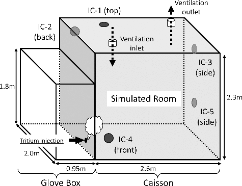
The experimental conditions of Scenarios (I)–(III) are summarized in . We conducted demonstration tests on conversion rate of tritium under three different conditions with a DS. shows a schematic illustration of the flow system for the tests. shows a stainless vessel of 12 m3 which was considered as a simulated tritium confinement room of a fusion facility [Citation8]. The behavior of overall tritium which were tritium + tritiated vapor + tritiated hydrocarbons in the simulated room was monitored by the ionization chambers of IC-1–IC-5 which were positioned as seen in . The simulated room was ventilated in advance. After the termination of ventilation, moisture or hydrocarbons were initially fed into the simulated room to be an adequate concentration. Concerning the moisture concentration, it was set to be 1.6 vol.% for Scenario (II). The mixture of methane, ethylene and propylene as a fire simulated gas was fed to the simulated room from a gas cylinder. The total concentration of the hydrocarbons was set to be 1.0 vol.% for Scenario (III). Then, tritium sealed in a container was moderately pushed out with a purge gas of N2 into the vessel. Tritium was intentionally released without forced convection in the simulated room. The initial concentration of tritium in the simulated room was set to be 1.0 GBq/m3. The gas flow rates were controlled with a mass flow controller (8500MC, KOFLOC, Japan) to be 1.3 —1.8 Nm3/h. The DS consisted of a preheater to stabilize the temperature of the main catalytic reactor, the main catalytic reactor and the dryer. The preheater was packed with ceramic balls to transfer heat smoothly to feed gas. The main catalytic reactor was packed with a hydrophobic platinum catalyst of SiO2 substrate named TKK-H1P manufactured by TANAKA KIKINZOKU KOGYO. K. K., Japan. The TKK-H1P catalyst was granular 3 mmφ and the platinum density per catalyst volume was 4 g/L [Citation12]. The TKK-H1P of 1000 cm3 was packed in the main catalytic reactor which inner diameter and length of the catalytic reactor were 96 mm and 200 mm, respectively. The packed density of the catalyst was 450g/L. The main catalytic reactor was thermally insulated. Temperature of catalyst layer in the main catalytic reactor was monitored with a thermocouple, and it was controlled with a wrapped heater. The dryer was packed with molecular sieves 3A (MS-3A) of 3 mm × 1.6 mm φ pellets manufactured by KISHIDA CHEMICAL Co., Ltd. The weight of the MS-3A packed in the dryer was 800 g. The dryer was continuously cooled by a cooling water circulation device not to lower the moisture adsorption performance by heat of adsorption.
Table 1. Experimental conditions of Scenarios (I)–(III).
Figure 1. A schematic illustration of flow system in demonstration tests using by the detritiation system.
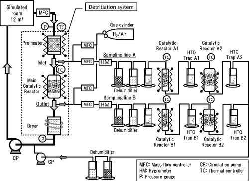
Two gas lines were branched from the inlet and the outlet of the main catalytic reactor to determine the efficiency for tritium oxidation in the main catalytic reactor. The sampling system A to determine the inlet tritium concentration and B to determine the outlet tritium concentration had the same configuration. The gas flow rate of both sampling lines was controlled with a mass flow controller to be 1000 Ncm3/min. Tritiated water (HTO) vapor in the sampling gas was removed by two dehumidifiers packed with silica gel beads and molecular sieves 3A pellets, respectively. The catalytic reactors A1 and B1 were to oxidize gaseous tritium and tritiated hydrocarbons except tritiated methane. The catalytic reactors were packed with TKK-H1P catalyst of granular 1 mmφ [12]. Hydrogen gas was intentionally added to be 1000 ppm in order to enhance the conversion rate of tritium. The catalytic reactors A1 and B1 were slender shape which inner diameter and length were 15.8 mm and 500 mm, respectively. The volume of TKK-H1P catalyst was 90 cm3 in order to fulfill the conversion rate of tritium higher than 99% [Citation16]. The reactors were thermally insulated and the temperature of catalyst was controlled to keep 473 K in order to combust gaseous tritium and tritiated hydrocarbons except tiritiated methane [Citation6]. The oxidized tritium (HTO) was collected by the water bubbler of the HTO Trap A1 and B1. The catalytic reactors A2 and B2 were especially to combust tritiated methane. The catalytic reactors were packed with a Pd/ZrO2 catalyst manufactured by TANAKA KIKINZOKU KOGYO. K. K [Citation17]. The palladium catalyst was cylindrical pellets of 3 mmφ × 3 mm and the palladium density per catalyst volume was 10 g/L. The catalytic reactors A2 and B2 were slender shape which inner diameter and length were 56.5 and 200 mm, respectively. The volume of the Pd/ZrO2 catalyst packed in the catalytic reactors A2 and B2 was 20 cm3 each. The catalytic reactors A2 and B2 were thermally insulated and the temperature was controlled to keep 773 K in order to combust tritiated methane. The oxidized tritiated methane was collected by the water bubbler of the HTO Trap A2 and B2. The measuring conditions of the sampling systems A and B are summarized in .
Table 2. Measuring conditions of the sampling systems A and B.
Tritium collected by the water bubbler of HTO Trap A1 and A2 was inlet tritium of the main catalytic reactor, and that of HTO Trap B1 and B2 was unreacted tritium in the main catalytic reactor. The conversion rate of tritium, CRT, by the main catalytic reactor is expressed as follows:
(1)
(1)
where AA1, AA2, AB1, and AB2 are tritium activity in water of the bubbler of the HTO Trap A1, A2, B1, and B2, respectively.
It is known that the oxidation reaction of tritium in a catalytic reactor is regarded as pseudo-first order of hydrogen concentration. A point to notice concerning our test conditions of the main loop is that the hydrogen concentration in air (initially 0.5 ppm) is much larger than tritium concentration. The conversion rate of tritium in the main catalytic reactor depends on hydrogen concentration in the simulated room. The overall reaction rate constant was evaluated using the experimentally obtained CRT as the following equation:
(2)
(2)
where koverall, Vcat, and Q are the overall reaction rate constant (s−1), the volume of catalyst (m3), and the volumetric flow rate (Nm3/s), respectively. From the obtained koverall, a volume of catalyst was determined as a function of the required conversion rate of tritium under a designated flow rate.
3. Results and discussion
3.1. How to spread tritium in a room in case of leakage
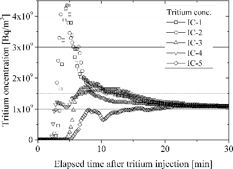
In general, tritium handling room will be continuously ventilated through the HVAC (Heating, Ventilation, and Air Conditioning) system. In case of a leakage of tritium in a ventilated room, tritium will be migrated smoothly. Hence, a tritium monitor for the trigger of termination of ventilation to isolate the room detects tritium leakage without delay. The smooth detection of leaked tritium has been demonstrated from both experimental and hydromechanics points of view [Citation18]. Even in case of tritium leakage in a room where ventilation has terminated for a few hours, tritium spread smoothly in the 12 m3 vessel as seen in . The concentration of tritium became constant within 30 minutes after tritium release without clear convection in the simulated room. This result suggests that the inequality in tritium concentration in a room needs not be cared in case of fire, since the natural convection due to differences in temperature will be contribute to the smooth migration of tritium in a room.
3.2. Scenario (I): detritiation behavior after an accidental leakage of tritium
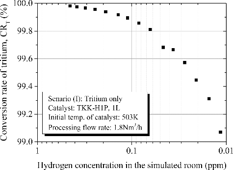
is indicative of detritiation behavior in case of an accidental leakage of tritium in the absence of both moisture and hydrocarbons. In , time zero of horizontal axis presents the start of DS operation. Tritium concentration in the 12 m3 vessel measured by ionization chambers (IC 1-5) gave total tritium concentration which counted tritium plus tritiated vapor. In the sampling line A in branched from the main loop line, tritium concentration in the 12 m3 vessel was separately evaluated with catalytic reactor A1 and HTO Trap A1. From the initial stage, tritium concentration monitored by the ICs is larger than that evaluated with the sampling line A. The reason is the contamination of ICs with tritiated vapor. Tritiated vapor produced by oxidation reaction of tritium in the main catalytic reactor was trapped with the dryer. In this scenario, concentration of tritiated vapor fed to the dryer was small. Hence, part of tritiated vapor which concentration was negligibly small but radioactivity was still large passed through the dryer. The tritiated vapor was absorbed on the surface of the ICs and caused the overestimation of tritium concentration [Citation19]. The overestimation of tritium concentration by IC has been reported [Citation18]. It should be noted that the overestimation becomes insignificance in case of high humidity around IC. The decrease in concentration gradually became slower with an increase in processing time. This was caused mainly by the delayed desorption of tritiated vapor from the surface of an IC.
Figure 4. Detritiation behavior in case of an accidental leakage of tritium in the absence of both moisture and hydrocarbons.
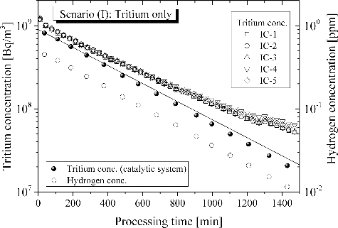
The solid line in presents the ideal detritiation where tritiated components fed to the DS is completely detritiated and tritiated components free gas was returned back to the 12 m3 vessel. The decrease in hydrogen concentration was evaluated from the decrease in tritium concentration since tritium was the tracer of hydrogen [Citation20,Citation21]. Compared measured detritiation performance shown with black dots with ideal detritiation, tritium concentration decreased along the ideal line with an increase in processing time. This result indicates the conversion efficiency of hydrogen does not drop largely depending on hydrogen concentration in the range of 0.01 to 0.5 ppm at catalyst temperature of 503K. shows the conversion rate of tritium as a function of hydrogen concentration in feed gas in the main catalytic reactor. The initial conversion rate was 99.98%. Then the conversion rate was gradually decreased with a decrease in hydrogen concentration in the gas fed to the DS. The decrease in hydrogen concentration was caused by detritiation with gas circulation. If once through detritiation is selected, hydrogen concentration in the gas will keep a constant value around natural concentration in air. In this assumption, conversion rate of tritium would keep a constant efficiency such as 99.98%.
3.3. Scenario (II): detritiation behavior after an accidental leakage of tritium with excess moisture
Tritium accompanied with excess moisture is one of the worst feed conditions for catalytic reactor. The primary reason is a possibly of initial drop in temperature of catalyst bed due to the sudden feed of moist air. In this case, it will require time until the temperature of catalyst bed has recovered. The initial drop in temperature of catalyst bed decreases conversion rate of tritium. is indicative of detritiation behavior in case of an accidental leakage of tritium in the presence of excess moisture. The change in both temperature of catalyst and the conversion rate of tritium in the main catalytic reactor are overlaid in the figure. The broken line presents the ideal detritiation. Tritium concentration decreased theoretically with processed time even under the excess moisture scenario. Previous research has suggested that moisture significantly reduces catalytic activity for oxidation of tritium since active sites of catalyst are covered with water layer [Citation11,Citation13]. This result is highly suggestive of a success in avoiding catalytic activity reduction by moisture with application of hydrophobic catalyst. The conversion rate of tritium in this scenario was slightly smaller than that in Scenario (I). Even so, the efficiency maintained more than 99% during the experiment. This result proves that hydrophobic catalyst can maintain its tritium oxidation activity on excess moisture conditions.
Figure 6. Detritiation behavior in case of an accidental leakage of tritium in the presence of excess moisture.
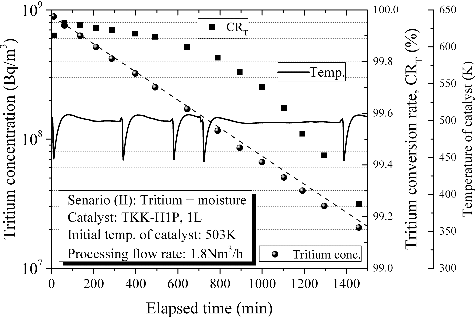
The temperature of catalyst bed was initially dropped by sudden feed of moist air. The periodical drops in temperature were caused by our restriction on operation which means a break of gas feed under the maintaining temperature of catalyst bed with a heater at night and the following resumption of gas feed at the next day. Every time the temperature of catalyst bed was dropped to 448K as the bottom temperature which would depend on the capacity of preheater. Then the temperature of catalyst bed had moderately recovered by temperature control with a heater. The drop in temperature of catalyst bed caused the decrease in conversion rate of tritium. The conversion rate at the bottom temperature was 99.90% and recovered to 99.95% with an increase in temperature. Any temporary decrease in conversion rate of tritium should be avoided as much as possible mainly by careful design. This result suggests that preheater plays a significant role in rapid recovery of temperature of catalyst bed once it is dropped by sudden feed of moist air.
3.4. Scenario (III): detritiation behavior after an accidental leakage of tritium with excess hydrocarbons
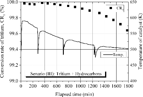
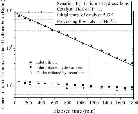
is indicative of detritiation behavior in case of an accidental leakage of tritium with excess hydrocarbons as a demonstration in an event of fire. The flow rate of the feed gas for the test was intentionally decreased to 1.3 Nm3/h considering thermal expansion of the gas by heat of reactions and maximum processing capacity of the applied pump. In this test, concentrations of both tritium and tritiated hydrocarbons at inlet and outlet of the main catalytic reactor were fractionally measured since production of tritiated hydrocarbons over catalytic reactor as a side reaction had remained an experimental challenge for DS related research. To fulfill requirements on conversion rate for reduction of tritium release to the environment as much as practically possible, a technical point is the suppression of the side reaction. In this demonstration, the tritium concentration theoretically decreased with processed time without any effect of catalyst poisoning by hydrocarbons. Concerning on the production of tritiated hydrocarbons over catalytic reactor as a side reaction, a very small amount of tritiated hydrocarbons were produced mainly at the initial stage of processing. It was confirmed that the concentration of tritiated hydrocarbons in the simulated room before processing through the experimental flow system was smaller than limit of detection (106 Bq/cm3). This gives support to the production of tritiated hydrocarbons over catalytic reactor through the gas processing in an event of fire. In the hydrocarbons, earlier study has suggested that ethylene and propylene have combusted completely in the catalytic reactor [Citation6]. The produced tritiated hydrocarbon is identified as tritiated methane. It has confirmed that the combustion rate of methane is negligibly small in the range of temperature measured in the test. Hence, concentration of tritiated methane was decreased gradually with processing time.
Figure 7. Detritiation behavior in case of an accidental leakage of tritium with excess hydrocarbons as a demonstration in an event of fire.
The conversion rate of tritium and temperature of the main catalytic reactor are shown in . Just after the start of gas processing, temperature of the main catalytic reactor increased steeply by heat of reaction of hydrocarbon combustion. The temperature of catalyst rose to 590 K at the peak. Then the temperature decreased gradually to the initial temperature according to the decrease in hydrocarbon concentrations. The conversion rate of tritium was initially 99.98%, then it decreased gradually with a decrease in hydrogen concentration. The conversion rate of Scenario (III) kept higher than those of the other scenarios due mainly to increase in temperature of catalyst by heat of reaction of hydrocarbons combustion.
The allowable peak temperature is a technical point from a design of catalytic reactor applicable to detritiation in case of abnormal events. The lowest temperature would be derived from a scenario of simultaneous release of tritium and SF6 in an event of fire, where SF6 is applied as electric insulation gas for neutral beam injection system (NBI) as plasma heating equipment [Citation22]. Taking this scenario into consideration, the allowable peak temperature should be lower than 623K in order not to decompose SF6 thermally [Citation23]. Thermal decomposition of SF6 causes the production of hydrofluoric acid and other fluoric components. Then they cause a severe corrosion on the inner surface of downstream equipment.
3.5. Evaluation of the amount of catalyst to fulfill the requirement on conversion rate
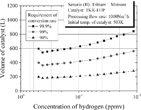
From the evaluated overall reaction rate constant for oxidation of tritium, the amount of catalyst, Vcat, was assessed with EquationEquation (2)(2)
(2) . Among the scenarios, Scenario (II) induces the maximum amount of catalyst to fulfill the requirements on conversion rate. Accordingly Scenario (II) is the most severe scenario for oxidation of tritium. shows the amount of catalyst as a function of hydrogen concentration in feed gas for Scenario (II). As for the conversion rate, we have considered three different efficiencies for comparison. For normalization, the processing flow rate, Q in EquationEquation (2)
(2)
(2) , was set to 1000 Nm3/h. Initial peak at 0.5 ppm of hydrogen concentration reflected the drop in temperature of catalyst bed due to the sudden feed of moist air mentioned above. Then the volume of catalyst increases gradually with a decrease in hydrogen concentration in feed gas. The result of suggests clearly that hydrogen concentration in processed gas is the dominant for the efficiency of tritium oxidation. In a recirculating mode of DS operation, conversion rate of tritium decreases with a decrease in hydrogen concentration in the processed gas. In a straight-through mode in which fresh air containing 0.5 ppm of hydrogen could be continuously introduced and later exhausted to the stack after passing through the DS, the volume of catalyst to fulfill the conversion rate of 99.9% is 600 L for 1000 Nm3/h of gas processing where the drop in temperature of catalyst bed due to the sudden feed of moist air has been taken into consideration. Needless to say, the conversion rate of tritium shall be determined as a requirement to the DS from the consideration of maximum tritium radioactive quantity leaked into the facility and an allowable dose at a site boundary line in an abnormal event.
4. Conclusion
Demonstration tests of tritium detritiation by the DS module were performed under the factorized fire scenarios: (I) leakage of tritium, (II) leakage of tritium with excess moisture, and (III) leakage of tritium with excess hydrocarbons. We evaluated the amount of catalyst based on kinetics to fulfill the requirements on conversion rate of tritium through the demonstration tests.
Tritium concentration in the simulated room decreased theoretically by the DS module connected with the simulated room in all the tested scenarios. The conversion rate of tritium was gradually decreased with a decrease in hydrogen concentration in the air fed to the DS in a recirculating mode of DS operation. In a straight-through mode in which fresh air containing 0.5 ppm of hydrogen could be continuously introduced and later exhausted to the stack after passing through the DS, conversion rate of tritium would keep a constant efficiency. The conversion rate of tritium in Scenario (II) was slightly smaller than that in Scenario (I), which was mainly caused by the effect of moisture in addition to the initial drop in temperature of catalyst. To recover conversion rate from the initial reduction smoothly, it is full of suggestion to optimize the power of preheater. In Scenario (III), the increase in temperature of catalyst by heat of reaction of hydrocarbons combustion caused the highest conversion rate without any effect of catalyst poisoning by hydrocarbons. In addition, it was confirmed that production of tritiated methane as a side reaction in a LTR was suppressed with the application of hydrophobic catalyst to the LTR.
We evaluated the amount of catalyst to fulfill the requirement on conversion rate of tritium based on Scenario (II) since this scenario was the worst for oxidation of tritium. In a straight-through mode in which fresh air containing 0.5 ppm of hydrogen is continuously introduced to the DS, the amount of catalyst to fulfill the conversion rate of 99.9% is 600 L per 1000 Nm3/h of gas processing with the hydrophobic catalyst TKK-H1P.
Acknowledgements
We would like to thank Mr Y. Tomiyama and Mr H. Ichimura for their considerable assistance in this experiment.
Disclosure statement
No potential conflict of interest was reported by the authors.
References
- Yamada H, Kasada R, Ozaki A, et al. Development of strategic establishment of technology bases for a fusion DEMO reactor in Japan. J Fusion Energy. 2016;35:4–26.
- Taylor N, Cortes P. Lessons learnt from ITER safety & licensing for DEMO and future nuclear fusion facilities. Fusion Eng Des. 2014;89:1995–2000.
- Naruse Y, Matsuda Y, Tanaka K. Tritium process laboratory at the JAERI. Fusion Eng Des. 1990;12:293–317.
- Perevezentseva AN, Andreev BM, Rozenkevich MB, et al. Wet scrubber technology for tritium confinement at ITER. Fusion Eng Des. 2010;85:1206–1210.
- Borgognoni F, Rizzello C, Tosti S. Experimental study of detritiation system catalyst poisoning. Fusion Eng Des. 2008;83:1375–1379.
- Edao Y, Sato K, Iwai Y, et al. Effect of hydrocarbons on the efficiency of catalytic reactor of detritiation system in an event of fire. J Nucl Sci Technol. 2016;53:1831–1838.
- Iwai Y, Sato K, Yamanishi T. Honeycomb palladium catalyst for the oxidation of tritiated hydrocarbons produced in tritium facilities. Fusion Sci Tehnol. 2014;66:214–220.
- Morfin F, Sabroux JC, Renouprez A. Catalytic combustion of hydrogen for mitigating hydrogen risk in case of a severe accident in a nuclear power plant: study of catalysts poisoning in a representative atmosphere. Appl Catal B Envir. 2004;47:47–58.
- Bixel JC, Kershner CJ. Catalytic oxidation and oxide adsorption for the removal of tritium from air. Proceedings of the 2nd AEC Environmental Protection Conference; 1974 April 16–19; Albuquerque, New Mexico, USA. p. 261–284.
- Iwai Y, Sato K, Yamanishi T. Change in activity of catalysts for the oxidation of tritium during a fire event. Fusion Eng Des. 2012;87:946–950.
- Munakata K, Takahashi K, Fukada S, et al. Removal of tritium released into air by catalytic oxidation and adsorption. Fusion Technol. 1995;28:918–923.
- Iwai Y, Sato K, Taniuchi J, et al. Room-temperature reactor packed with hydrophobic catalysts for the oxidation of hydrogen isotopes released in a nuclear facility. J Nucl Sci Technol. 2011;48:1184–1192.
- Nishikawa M, Takeishi T, Enoeda M, et al. Catalytic oxidation of tritium in wet gas. J Nucl Sci Technol. 1985;22:922–933.
- Forzatti P, Lietti L. Catalyst deactivation. Catal Today. 1999;52:165–181.
- Zhu X, Cheng B, Yu J, et al. Halogen poisoning effect of Pt-TiO2 for formaldehyde catalytic oxidation performance at room temperature. Appl Surf Sci. 2016;364:808–814.
- Edao Y, Iwai Y, Hayashi T. Development of quantitative analysis method for tritium using by hydrophobic platinum catalyst. Nucl Mater Energy. 2016;9:273–277.
- Iwai Y, Sato K, Yamanishi T. Pd/ZrO2 Catalyst for the oxidation process of tritiated organic substances produced in fusion plants. Fusion Sci Technol. 2012;62:83–88.
- Iwai Y, Hayashi T, Yamanichi T, et al. Simulation of tritium behavior after intended tritium release in ventilated room. J Nucl Sci Technol. 2001;38:63–75.
- Matsuyama M, Ichimura K, Ashida K, et al. Contamination of ionization chamber due to tritium exposure. Fusion Technol. 1985;8:2461–2466.
- Stodilka D, Kherania N, Shmayda W, et al. A tritium tracer technique for the measurement of hydrogen permeation in polymeric materials. Int J Hydrogen Energy. 2000;25:1129–1136.
- Ikeda T, Otsuka T, Tanabe T. Hydrogen permeation in metals near room temperature by a tritium tracer technique. J Nucl Mater. 2011;417:568–571.
- Simonin A, Esch H, Doceul L, et al. Conceptual design of a high-voltage compact bushing for application to future N-NBI systems of fusion reactors. Fusion Eng Des. 2013;88:1–7.
- Kobayashi K, Miura H, Hayashi T, et al. Oxidation performance test of detritiation system under existence of SF6. Fusion Sci Technol. 2007;52:711–715.

