
 ?Mathematical formulae have been encoded as MathML and are displayed in this HTML version using MathJax in order to improve their display. Uncheck the box to turn MathJax off. This feature requires Javascript. Click on a formula to zoom.
ABSTRACT
During nuclear power plant maintenance, the multi-stud tensioning machine is used to perform opening/sealing the cap of the reactor pressure vessel. This process incorporates elongations of 58 studs, whose extension values are monitored in real time by measurement meters. Conventionally, the placements of the meters are performed by human labor, which is time consuming and radioactively hazardous. In this paper, we introduce an automated measurement robot system, consisting of 58 node robots and multiple field bus based distributed control devices, to complete meter placement and data acquisition tasks without human involvement in the hazardous working site. In order to eliminate the swing phenomenon of the wire-driven meter adaptor on the robot distal end, extra-insensitive input shaper is employed for robot motion control, thus saving the overall operation time from traditionally over 10 minutes to less than 22 s.
1. Introduction
By the year of 2016, nuclear power will share no less than 13% of all electricity production in the world, and more than 60 new nuclear power plants are under construction. According to the nuclear energy development strategies of China, nuclear power should share no less than 4% of total installed power capacity and no less than 6% of total electricity production by the year 2020. Relevant technology development and application are in vast demand and have been paid much attention to in recent years. Equipment is used under the environment with irradiation, high temperature, and high pressure. By using robots for equipment maintenance, radioactive waste transportation, and emergency management, we can significantly improve the efficiency of operation and reduce the radiation dose to human operators.
Back to the early 1940s, there began to emerge automated systems used in radiative hazardous environments [Citation1]. There have been many types of towards nuclear power plant robotic system by now [Citation2–6]. The Monirobo, developed by Japan, was used to detect radiation dose, environment temperature, level of moisture, and dust and flammable gas [Citation7]. It had camera shooting ability as well. With a volume of 800 × 1500 × 1500 mm and a weight of 600 kg, the due caterpillar track robot could reach a velocity of 40 m/min, and a maximum communication distance of 1100 m. It could also work functionally under high radiation own to a radiation-proof material surface layer. A research group in Chiba Institute of Technology developed an amphibious robot named Sakura II, which was capable of patrolling, climbing, obstacle crossing underwater. Aiming at working in harsh hazardous surroundings, this robot was employed in the inspection and rescuing tasks during Fukushima Nuclear Power Station accident. It also participated in the waste clean-up procedures after particular upgrades [Citation8]. In China, an underwater manipulation robot was proposed by Beihang University to perform remote-controlled moving and grasping inside a reactor tank [Citation9]. Earlier, our research group introduced a blocking plate manipulation robot system, which had a three degree-of-freedom (DOF) arm and a radiation-proof camera, to automatically perform stud-tightening tasks on the water pipe's 45° head face inside a steam generator [Citation10]. The robot systems mentioned above are all designed for nuclear power station operation and maintenance, in order to improve working efficiency and reduce human labor in hazardous environment. These cases are helpful during the design of our system, in speaking of material choice, anti-radioactive measurement, and actuation technique. However, automated robot systems for the multi-stud tensioning machine (MSTM) measurement tasks are seldom reported to the state of art.
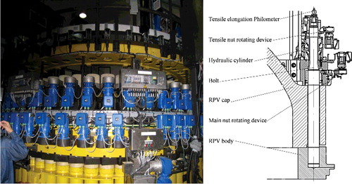
In this paper, we introduce an automatic measurement system for the MSTM. As shown in , the MSTM is a specialized equipment in a nuclear power plant for opening and sealing the cap of the reactor pressure vessel (RPV) [Citation11]. There are 58 studs that hold the RPV cap flange and body, and the opening/sealing procedure thus becomes the operation of the studs. A typical workflow of sealing the cap is as follows: (Equation1(1)
(1) ) placement of the studs in the position holes; (Equation2
(2)
(2) ) pre-positioning of the nuts; (Equation3
(3)
(3) ) placement of measurement meters from storage positions to working positions; and (Equation4
(4)
(4) ) elongations of the studs under hydraulic oil pressure until demanded length. The 58 meters monitor the stud elongations simultaneously in order to keep the balance and safety of the procedure; (Equation5
(5)
(5) ) tightening of the nuts; (Equation6
(6)
(6) ) decompression of the hydraulic system, in other words, releasing of the studs; (Equation7
(7)
(7) ) measurement of residual extension values, if desirable, and (Equation8
(8)
(8) ) reposition of the measurement meters to storage positions [Citation12].
Figure 1. The structure of a multi-stud tensioning machine.
At present, steps (Equation3(3)
(3) ) and (Equation8
(8)
(8) ), or meter placement tasks, are performed by human labor. This is an onerous and dangerous process for a worker wearing protective paper suit. The meter storage positions are on the MSTM's outer ring which is at the edge of human reach, and the working positions are below the walking surface, adding difficulty for the placement task. Each positioning costed about 10 seconds, and for 58 meters it led to a total operation time over 10 minutes, considering ladder climbing onto and off the MSTM.
In order to improve working efficiency and reduce radiation hazard to human, we put forward and develop an automatic measurement robot system to replace human labor. The system has 58 node robots and an FPGA (Field Programmable Gate Array)-based distributed control scheme to realize meter placement and to achieve high-speed data acquisition. In addition, a human–machine interface is developed to monitor the operation process and to communicate with the existing MSTM control programmable logic controller (PLC). The meters incorporated in the node robots are fixed in adaptors and carried by steel wires, thus an anti-swing control algorithm is proposed to eliminate the swing phenomenon before lowering the adaptors onto working positions. Simulation, experiments and field tests demonstrate the system design and the effectiveness of the control methods. To the best of our knowledge, this paper represented the first robot system specialized for real-time measurement for the MSTM.
2. System overview
2.1. System framework
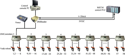
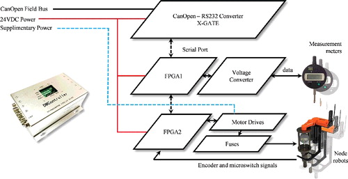
shows the whole system framework. There are 58 2-DOF node robots to perform meter placements and measurements. Each eight robots share a DMController, which receives commands from the measurement system's control console and controls the node robots, as well as acquires meter data and sends the data up to the control console. DMControllers are connected via CanOpen field bus, and the host node lies in the DMReader, which communicates with the control console PC through USB. The DMReader is also the port to the MSTM control PLC. By reading a current signal (4–20 mA), it gets the pressure of the hydraulic system, and by sending an I/O signal (5 VDC) it reports emergency statuses to the MSTM control PLC.
Figure 2. System framework.
2.2. Workflow
The typical workflow of the proposed automated measurement system, working with the MSTM control PLC, is listed as follows:
A gantry frame lifts the MSTM onto the RPV and aligns the studs with the nuts;
A technician chooses the desired measurement spots (arbitrary from the 58 nodes) on the human–machine interface according to the demand of operation. After receiving the control signal, DMControllers command corresponding node robots to move to working positions. The DMReader starts to translate the MSTM control PLC's current signal to pressure value. Compared to a preset pressure threshold, the system can judge if the elongation process is steady as expected.
Meter readings are set to 0. The technician manually starts RPV pressuring process, and the studs begin to be elongated. Meters send readings through DMControllers to the control console in real time, and the pressuring process goes on as long as current stud elongations are within the preset threshold. During this process, if any stud elongation value exceeds the threshold, the control console sends a stop signal through the DMReader to the MSTM control PLC to stop pressuring, then the technician handles the problem manually. This step is repeated until desired pressure is achieved.
Sealing the RPV cap: after the pressuring procedure is finished, the nuts are rotated to be tightened, the pressure is released and the meters give the residual extension values. If these values are also within an acceptable range, the sealing process is completed, and the robots carry the meters back to their storage positions. Or,
Opening the RPV cap: after the pressuring procedure is finished, the nuts are rotated to be loosened and the pressure is released, then the robots carry the meters back to their storage positions.
3. System design
3.1. Node robots
Although the MSTM is a large platform in speaking of its volume, room left for the measurement system is strictly limited in to a flat ring space. Each node robot has to fit in a maximum volume of 230 × 235.5 × 278 mm ((a)). The working positions of the meters are overlapped with the channels where other equipment also move through, thus the robots have storage positions so as to keep clear of the channel areas ((b)). (c) shows the mechanical design of a node robot. Each robot has 2 DOFs driven by DC motors. The first joint rotates the robot arm to move the meter back and forth in top view. The second joint lifts or lowers the meter via a 0.8 mm steel wire. The meter is fixed in an adaptor with a segmented-slope bottom which makes its locating easier. The robot is made of 1060 aluminum alloy in order to decrease its body weight and to enhance its anti-radioactive ability.
Figure 3. Spatial analysis and CAD design of the node robots. (a) The constraint space for the measurement system on the MSTM. (b) Top view of the node robot mounted on the test platform. (c) The 2-DOF node robot. (d) The 1:1 scaled MSTM test platform.
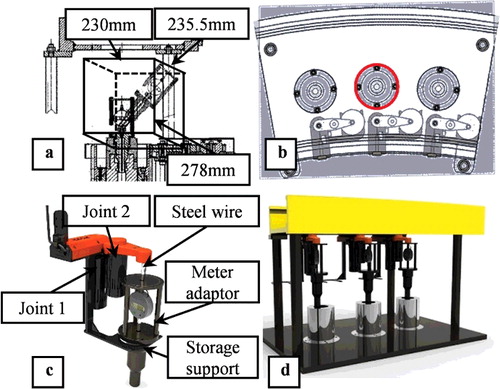
As shown in (d), a 1:1 scaled MSTM segment was built to test the node robot prototypes, with respect of workspace, mechanical design, and stiffness. The robot mechanism is able to locate the meter adaptors right above the working spots, and there are no interferences between each two adjacent robots.
shows the six key statuses during the robot operation. First, joint 2 rotates the wire wheel and lifts the meter adaptor until it hits the microswitch attached at the distal end of the robot arm (status a), costing about 3 seconds. Then joint 1 rotates the robot arm towards above the working position (status b), costing about 5 seconds. Joint 2 lowers down the meter adaptor for a few seconds to reach the working position (status c), costing about 5 seconds. Now the meter is attached to the MSTM and ready for measurement. When drawing back the meter, joint 2 lifts the meter adaptor up (status d), joint 1 rotates the robot arm towards the storage position (status e), and joint 2 lowers the meter adaptor until onto the storage position (status f).
Figure 4. Key statuses in the workflow of a node robot.
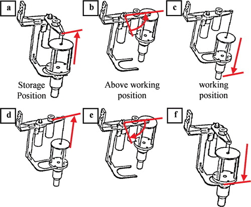
Notably, at status c and status f, the wire is a bit longer than the needed travel distance. When on the working position (status c), the meter adaptor's lower surface should be stably seated on the MSTM's upper surface. By releasing the wire slightly longer than the distance, we can guarantee the tight contact between the two surfaces. When the robot is moved away from the working position after measurement procedure, the meter adaptor hang by the wire may swing or shake during MSTM platform operation. The storage position (status f) is designed to offer a steady spot for the adaptor, loose wire can eliminate the strain in it, thus improve the safety during storage and the wire's endurance life.
3.2. DMController
The DMControllers are CanOpen filed bus slave stations. Each DMController is the control center for the nearby eight node robots. As shown in , it incorporates two FPGAs and one communication board. The base board, with one FPGA, motor drivers and fuses, is to control the node robots. The middle board, with one FPGA and voltage converting circuit, is to acquire data from the measurement meters. The upper board employs a CanOpen-RS232 converter module (XGate-COP10, ZHIYUAN ELECTRONICS CO., LTD, China) and other status indicators and switches.
Figure 5. Framework of the DMcontroller.
The information flow among the boards are as follows. FPGA 2 controls the robot motors and sends robot statuses to FPGA 1 through serial port, while FPGA 1 collects meter data and translates them to extension values, then sends all the data to the communication board via serial port. The communication board uploads the data onto the Can bus, while receives commands from the control console and sends them downwards.
To improve the electronic reliability of the DMController, the power for the logical circuit and the power for motors are separately supplied from different power sources. This also enables a controller to sustain measurement function even when the robot control is down in extreme scenarios.
The positionings of total 58 meters are simultaneous. The working current of each motor is less than 0.1 ampere, howerver, the instantaneous starting current goes up to 1 ampere. The total current exceeds 58 ampere if all motors start motion at the same time, which is intolerable for the power cable which can hold a maximum current not greater than 16 ampera. As a solution, eight robots controlled by each DMController are started successively with 1 second delays (7 seconds in total), which reduces the maximum current on the cable less than 10 ampere. There is also a system check costing about 1-2 seconds after all motor motions are done, making the total operating time 21–22 seconds.
3.3. DMReader
The DMReader has two functions: connection between the control console PC and the CAN bus; communication with the MSTM control PLC. A CanOpen master card (USBCAN-E-P, ZHIYUAN ELECTRONICS CO., LTD, China) is installed in the DMReader and connected to the control console PC through USB. A converter circuit is designed based on an ATmega16 SCM. It translates the 4–20 mA signal representing current pressure from the MSTM control PLC to a 0–5 V analog signal (representing RPV pressure), and gives back a 0/5 VDC emergency signal if necessary.
3.4. Software
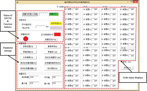
Software used on the control console PC is built with Microsoft Visual Studio C++. The human–machine interface displays all 58-node statuses. Two interfaces are designed for meter data monitoring and robot control, respectively. On the data monitoring interface, there are functions and displays such as system login, meter readings, pressure, system enable/unable, parameter settings, parameter load, screenshot, emergency stop, etc. As shown in , for the operator's convenience, node selection options can be easily selected by clicking on corresponding buttons, for example, odd nodes, even nodes and custom mode. A system dialog is recorded in background for backtrack uses.
Figure 6. A screenshot of the human–machine interface.
3.5. Safety strategies
As a specialized equipment used in the reactor area in a nuclear power plant, safety is one of the most vital considerations in our design. Multiple measures are taken to improve the system safety as follows:
Separation of power supply
As mentioned in Section 3.2, motors are powered from a distinguished source to avoid electromagnetic interference with logic circuits.
Component redundancy
All microswitches, used to detect robot status, are doubled in case of mechanical failure.
Failure safe
It is very unwilling to have objects fallen into the RPV system from the MSTM. In our design, joint 1 has mechanical structure to limit the robot arm movement range and there is a safety strip connecting the robot body and the meter adaptor. Each motor has a fuse to limit the maximum current. These measures are not likely to be activated, but are necessary as fail safes in extreme unexpected situations.
Anti-radioactive ability
To extend the service life of the robot system, aluminum alloy is employed to build robot body structure and controller boxes. Other parts, say, some ABS shells, are sprayed with anti-radioactive paint. The robots and controllers have regular geometry appearance for easy cleaning. All cables are double shielded and strengthened with woven material coating.
Software monitoring
DMControllers and control console PC both have built-in timers (watch dogs) to monitor robot movements. If the robot did not reach an expected position within a certain time window, corresponding motors would be shut down and errors would be shown on the interface.
4. Swing control
The meter adaptor overhangs the distal end of the robot arm, therefore the adaptor starts to swing while joint 1 is in motion. This problem leads to an imperative resting time lasting for tens of seconds before joint 2 can lower the adaptor. Otherwise, the adaptor may hit the adaptor holder on the MSTM or even worse, if the swing amplitude is too large, run out of it. To eliminate this phenomenon and to increase working efficiency, we propose a control approach based on extra-insensitive (EI) input shaper.
4.1. Modeling of the node robot
The rotation of the robot arm generates gyratory movement of the meter adaptor. In order to model this pendulum system, a few simplifications are made:
The pulley which hangs the steel wire is simplified as a point;
The meter adaptor is simplified as a mass point;
Mass of the steel wire is ignored; and
Air resistance is ignored.
Now we can build the model of the meter adaptor movement relatively to the robot body. As shown in , the origin of the base frame OXYZ is set along the motor shaft of joint 1, in the same plane with the robot arm. Frame is set on the robot arm with the same origin. Let ψ be the angle between axis OX and
, while ρ and l are the lengths of the swing arm and the wire, respectively. The coordinate of the pulley can be calculated as (ρcos ψ, ρsin ψ) and the angle between the wire and axis
can be decomposed into θ and φ, with respect of plane
and
. Therefore, the coordinate of the mass point relatively to the robot body (in vector format) is:
(1)
(1)
Figure 7. Modeling of the node robot.
Let J represent the moment of inertia of the robot arm, thus the kinetic energy of the swing system (T) is:
(2)
(2)
Assume the potential energy on plane OXY is 0, then the potential energy of the mass point (V) is:
(3)
(3)
According to the Lagrange equation, L = T − V, we have:
(4)
(4)
Where, qi represents the four variables in the generalized coordinate(ρ, ψ, θ, ϕ). Corresponding generalized force Qi(FP, Tψ) incorporates the force along axis Ox1 and the torque about axis Oz. Forces that generating θ and ϕ are conservative forces, which means Qθ = Qϕ = 0 and we have two differential equations as:
(5)
(5)
4.1. EI input shaper
The basic idea of an input shaper is to reduce vibration by planning of control input. It uses as the system input the convolution of the original input and a series of different amplitudes and time sequences [Citation13–15].
Multi-impulse input shaper expressed in the time domain is given as:
(6)
(6)
Residual vibration (V) is the ratio of the system unit impulse response after and before adding in the input shaper, after n impulses (t > tn). It is expressed as:
(7)
(7)
where,
(8)
(8)
(9)
(9)
where, ω and ϵ are the frequency and damping of the system, respectively.
The goal of an input shaper is to make the superposition of the vibration caused by different impulses become zero, which means, making EquationEquation (8)(8)
(8) and EquationEquation (9)
(9)
(9) equal to 0. With this purpose, a series of input shapers can be designed, such as the zero vibration (ZV) input shaper, the zero vibration derivative (ZVD) input shaper and the EI input shaper. According to the analysis in [Citation16], an effective ZV input shaper requires critically on a precise model, while the EI input shaper has the best robustness, which does not mandate an absolute 0 at the system intrinsic vibration frequency, but a residual vibration amplitude not greater than a tolerated value (Vexp ) near the intrinsic frequency. In our case, the assemblies of 58 robots inevitably have inconformity; therefore, we choose the EI input shaper which gives constraints as:
(10)
(10)
Where, ωn is the system intrinsic vibration frequency, ωn − n1 and ωn − n2 are two frequencies near ωn.
Put EquationEquation (10)(10)
(10) into EquationEquation (7)
(7)
(7) and we have:
(11)
(11)
where, T is the vibration cycle of the system.
(12)
(12)
5. Simulations and experiments
5.1. Simulation of the swing control approach
According to the robot model analysis in Section 4, the robot dynamic simulation is carried out using Matlab and Adams so as to verify that the EI input shaper can reduce the vibration amplitude of the meter adaptor.
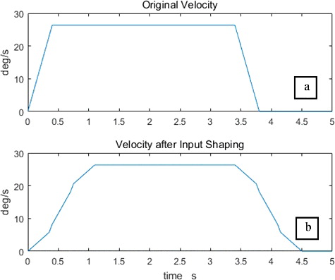
As shown in (a), the original motor control velocity is trapezium-shaped. It means that the motor starts from rest and accelerates with uniform acceleration. Then the motor reaches a constant maximum speed. Finally, the motor decelerates and the meter adaptor reaches the target position. Using the EI input shaper designed, by convolution between original velocity and EquationEquation (11)(11)
(11) , the input velocity becomes as shown in (b).
Figure 8. (a) The original velocity and (b) the velocity after input shaping.
shows the simulation scheme. A robot model is built in Adams. The original and after-shaped robot arm velocities are imported from Matlab results as control inputs. The swing angles θ and ϕ are recorded for observation, as shown in .
Figure 9. Input shaping simulation scheme.
Figure 10. Simulation results.
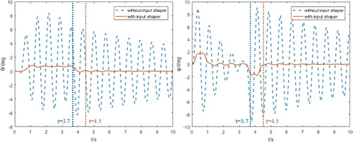
When the input is the original velocity, the maximum swing angle θ and ϕ both exceed 8°, respectively. Although the swing decreases because of the damping between the wire and the wheel, it can lead to a great swing phenomenon during robot arm motion. If joint 2 starts lowering down the meter adaptor immediately after joint 1 stops (at 3.7 s), θ and ϕ still exceed 6° and 8° during the process, which causes failure to insert the adaptor into the position hole, as shown in . As measured from the cross-section drawing, the angles must stay below 3° to guarantee a successful positioning.
Figure 11. The analysis of swing amplitudes.
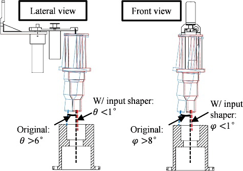
After employing the EI input shaper, maximum angle value of θ and ϕ decrease to about 1° and 2°, respectively. If joint 2 starts motion right after joint 1 stops (at 4.5 s), the angles both stay below 1° throughout the process. The proposed approach achieves significant improvement on motion stationarity, and it saves more than 10 seconds from each meter operation process as well.
5.2. Experiment of the swing control approach
To test the proposed anti-swing algorithm, we set up an experiment on the aforementioned 1:1 scaled test platform. As shown in (a), a node robot is fixed at the center location of the platform, and two CCD cameras (DH-HV1351UM, resolution 2048 × 1536 pixels, 30 fps, IMAVISION, Beijing, China) are employed to record data during the experiment. The cameras are located on the x-axis and y-axis to capture images from front and lateral view, respectively.
Figure 12. Experimental method of swing control. (a) Experimental environment. (b) Measurement of a swing angle from key frame.
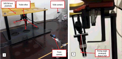
The recording begins at the same time with the robot's motion and lasts for 10 seconds. The images are processed in the following steps. First, key frames are extracted when the meter adaptor swing to the maximum amplitude during each period. Then, swing angles are manually measured from key frames ((b)). The data obtained from trials without and with the proposed EI input shaper are plotted in .
Figure 13. The swing data from trials.
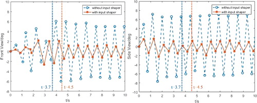
Though the cameras are fixed, which means and have different view angles before motor 1 stops, the figures still incorporate integrated information of the adaptor's motion. Also, after motor 1 stops, the view angles become the same. shows that the swing process after motor 1 stops is quite comparable with the simulation result, in speaking of frequency and maximum swing angle. By employing EI input shaper, the maximum swing angle decrease from nearly 8° to below 2°, which demonstrates the effectiveness of the proposed control method.
5.3. Endurance tests
A series of practical tests are carried out on an extended mock-up testing platform (), including:
Endurance test
Figure 14. The mock-up platform for full-load test. Robots grouping are shown in the bottom left subfigure.
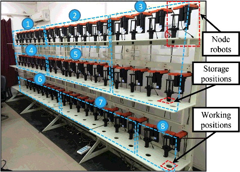
Each robot runs back and forth over 400 times to ensure that the steel wire is adequately strong and the mechanical assembly is reliable.
Failure simulation
Extreme situations are intendedly made to test if all possible errors can be handled automatically by the system itself. For instance, scenarios such as motor overload, overtime motion, steel wire break, cable unplugging can test the fuse/mechanical limit, built-in timer, safety strip, and software robustness, respectively.
Full load test
With all 58 node robots connected, we are also able to test the system in speaking of power supply efficiency, communication speed, and system reliability.
5.4. Irradiation test
Irradiation test was conducted at Radiation Technology Research Institute of Suzhou University. The estimated radiation intensity on the working site is about 1.5 mSv/h. Therefore, as shown in (a), one-node robot prototype was set at the test location where the actual intensity was 1.69 mSv/h, while a Co-60 irradiator was employed to produce radiation. Co-60 γ beam was projected from the top the robot while other parts of the robot were under coverage of the scattered radiation. Two dosimeters were attached on the robot body, as shown in (b).
Figure 15. Setup for the radiation test.
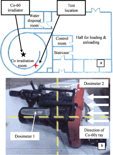
After a testing period of 80 h, the total absorbed dose of dosimeter 1 and 2 were 123.6 mSv and 131.3 mSv, respectively. The radioactive environment where the robot system works in does not allow long-time human presence, however, it is not a very high-dose radiation that can immediately damage mechanical and electronical parts of the robot, either. We ran the system's every function before and after the 80-hour procedure in the test facility, and the result verified the system reliability under radioactive circumstances.
5.5. Field tests
The system was shipped to the testing center of China Nuclear Power Technology Research Institute where field tests were carried out under semi-authentic environment (). The testing facility incorporated an RPV, an MSTM and relevant control consoles. The automated measurement system was installed onto the MSTM and connected to its control PLC.
Figure 16. Setup of system field tests.
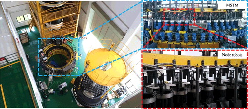
After basic adjustments, the system was tested in full load and the results were satisfactory that the robot worked functionally without interference with the existing MSTM, the control system ran functionally, and the human–machine interference displayed data in a rapid and comprehensive way.
6. Conclusion
In this paper, an automated measurement robot system was developed for the MSTM in a nuclear power plant. With 58 2-DOF node robots, this system replaces human labor in placing measurement meters to monitor the stud elongation process. Mechanical design, control system design, and safety strategies were introduced, and a motion control approach based on EI input shaper was proposed for swing reduction during robot control. Simulations, experiments, and field tests demonstrated effectiveness of the system, in terms of endurance, safety, and efficiency. As a result, it can save the overall operation time from conventionally over 10 minutes to less than 22 s.
The system shown in this paper was the fifth iteration, and it is currently undergoing long-term tests in testing centers of different nuclear power plants in China, and hopefully the next generation products now being developed by our research team would be tested in real working sites in the future.
Acknowledgments
This work is supported by National Natural Science Foundation of China [grant number 61375106], [grant number 61673064] and [grant number U1613221].
Disclosure statement
No potential conflict of interest was reported by the authors.
Additional information
Funding
References
- Byrd JS, De Vries KR. A six-legged telerobot for nuclear applications development. Int J Robot Res. 1990;2(9):43–52.
- White T, Hewer N, Luk BL, et al. The design and operational performance of a climbing robot used for weld inspection in hazardous environments. IEEE International Conference on Control Applications; 1998 Sep 1–4; Trieste (Italy). p. 451–455, vol.1.
- Abouaf J. Trial by fire: teleoperated robot targets Chernobyl. IEEE Comput Graph Appl. 1998 Jul/Aug;18(4):10–14.
- Sugiyama S, Tanaka K, Numata N, et al. Quadrupedal locomotion subsystem of prototype advanced robot for nuclear power plant facilities. International Conference on Advanced Robotics; 1991 Jun 19–22. p. 326–333, vol.1.
- Xu W, Mao Z. [Research status and development trend of nuclear power plant robots]. Robot. 2011;53:623–627. Chinese.
- Sands D. Cost effective robotics in the nuclear industry. Ind Robot. 2006;33(3):170–173.
- Kawatsuma S, Fukushima M, Okada T. Emergency response by robots to Fukushima‐Daiichi accident: summary and lessons learned. Ind Robot. 2012;39(5):428–435.
- Toda K, Yamato K, Kodachi T, et al. Camera arm system for disaster response robots. International Conference on Design Engineering and Science; 2014 Agu 31–Sep 3; Pilsen (Czech Republic). p. 80–85.
- Dong M, Chou W, Fang B, et al. Implementation of remotely operated vehicle for direct inspection of reactor pressure vessel and other water-filled infrastructure. J Nucl Sci Technol. 2016;8:1–11.
- Duan X, Wang Y, Liu Q, et al. Manipulation robot system based on visual guidance for sealing blocking plate of steam generator. J Nucl Sci Technol. 2016;53(2):281–288.
- Cui X, Chen Z, Liu S. Application control of multi stud tension machine in sealing process of reactor pressure vessel. Press Vessel Technol. 2014;10:69–74. Chinese.
- Li M, Duan X, Li H, et al. Control and experimental validation of robot-assisted automatic measurement system for multi-stud tensioning machine (MSTM). IEEE International Conference on Robotics and Automation; 2016 May 16–21; Stockholm (Sweden). p. 2816–2821.
- Lawrence J, Singhose W. Command shaping slewing motions for tower cranes. J Vib Acoust. 2010;132(1):325–326.
- Pao L, Singhose W. Unity magnitude input shapers and their relation to time-optimal control. Proceedings of the IFAC World Congress; 1996 Mar. p. 385–390.
- Singhose WE, Seering WP, Singer NC. Shaping inputs to reduce vibration: a vector diagram approach. IEEE International Conference on Robotics and Automation; 1990 May 13–18; Tsukuba (Japan). p. 922–927.
- Xiong W, Liang Y, Wu L, et al. Anti-swing control of crane system based on input shaping technique. Comput Digit Eng. 2011;39(3):148–151. Chinese.