
 ?Mathematical formulae have been encoded as MathML and are displayed in this HTML version using MathJax in order to improve their display. Uncheck the box to turn MathJax off. This feature requires Javascript. Click on a formula to zoom.
ABSTRACT
When pressurized water or vapor leaks from a failed heat transfer tube in a steam generator of sodium-cooled fast reactors, a high-velocity and high-temperature jet with sodium–water chemical reaction may cause wastage on the adjacent tubes. For safety assessment of the steam generator, a computational fluid dynamics code called SERAPHIM calculating compressible multicomponent multiphase flow with sodium–water chemical reaction has been developed. The original SERAPHIM code is based on the finite difference method. In this study, unstructured mesh-based numerical method for the SERAPHIM code was developed to advance a numerical accuracy for the complex-shaped domain including multiple heat transfer tubes. Numerical analysis of an underexpanded jet experiment was performed as part of validation of the unstructured mesh-based SERAPHIM code. The calculated pressure profile showed good agreement with the experimental data. To investigate the effect of the introduction of the unstructured mesh and to confirm applicability of the numerical method for the actual situation, water vapor discharging into liquid sodium was analyzed. The calculated behavior of the reacting jet agreed with the previous experimental knowledge. It was demonstrated that the proposed numerical method could be applicable to evaluation of the sodium–water reaction phenomenon.
1. Introduction
In a steam generator (SG) of sodium-cooled fast reactors, heat exchange takes place between liquid sodium in a shell side and water inside a heat transfer tube. When pressurized water or vapor leaks from a failed heat transfer tube, a high-velocity, high-temperature, and corrosive jet with sodium–water chemical reaction is formed in the shell side as shown in . It is known that the reacting jet may cause wastage on the adjacent tubes. Wastage is due to erosion, flow accelerated corrosion, or combination of them. Significant progress of wastage or degradation of a mechanical strength by temperature rise may result in secondary failure (failure propagation) on the adjacent tubes. The tube failure propagation will lead to expansion of the damage and long-term shutdown of the plant.
Figure 1. Reacting jet under tube failure accident.
Prevention of the failure propagation is one of the major concerns in designing the SG. Our goal is to construct a computational method evaluating possibility of failure propagation occurrence. A computational method has a great advantage over the conventional evaluation method based on exhaustive demonstration experiments in terms of a cost, development period, and range of application. As shown in , a multiphysics computational evaluation system comprising the multiple computational fluid dynamics (CFD) codes was newly constructed for design and safety evaluation of the SG in our study. The evaluation system includes modeling of multiphase flow, heat and mass transfer, chemical reaction, stress generation, variation of material properties, and failure of material. As one component of the system, a CFD code called SERAPHIM (Sodium-watEr Reaction Analysis: PHysics of Interdisciplinary Multi-phase flow) was developed to calculate compressible multicomponent multiphase flow with sodium–water chemical reaction [Citation1–6]. The SERAPHIM code is based on the mechanistic numerical models. The multidimensional multifluid model considering compressibility and a numerical model for chemical reaction which occurs at the interface between water vapor and liquid sodium was developed in our previous studies. This enabled us to calculate the reacting multiphase flow with water, liquid sodium, and multicomponent gas.
Figure 2. Multiphysics evaluation system for tube failure accident.
The original SERAPHIM code uses the finite difference method. When a structured mesh is applied to the domain in which the heat transfer tube bundle exists, the tubes are modeled in a staircase pattern. In this case, significantly fine meshing is required to achieve enough resolution for the tubes, leading to large number of computational cells. On the other hand, an unstructured mesh can represent the curvilinear surface of the tubes with the relatively low number of the computational cells. In addition, the structured mesh has a problem to analyze the situation including multiple jets after the secondary failure. The secondary leakage will be formed diagonally to the axis of the primary jet. In this case, correct meshing for the secondary leakage on the surface of the target tube becomes extremely difficult. From these reasons, an unstructured mesh-based numerical method for the compressible multicomponent multiphase flow with sodium–water chemical reaction was developed and introduced into the SERAPHIM code in this study.
This paper focuses on construction of the unstructured mesh-based numerical method, investigation into fundamental validity of the method through the analysis of an underexpanded jet, and the test analysis on the reacting jet. Water vapor blowing out from an opening of the failed tube forms the underexpanded jet because a critical pressure of water vapor inside the tube is higher than a sodium-side ambient pressure. The gaseous underexpanded jet is one of the key phenomena under the tube failure accident. Numerical analysis of a three-dimensional underexpanded air jet in air was first performed to investigate validity of the unstructured mesh-based governing equations and the solution method considering compressibility. Kuehner et al. [Citation7] and Woodmansee et al. [Citation8] measured the profile of the pressure along the centerline of the underexpanded air jet in air by using the coherent anti-Stokes Raman scattering technique. The calculated pressure was compared to their experimental data. In addition, the test analysis on water vapor discharging into liquid sodium was performed to confirm a basic capability of the numerical method and to compare the effect of two types of meshing approaches. The hypothetical computational domain constructed for this test analysis consists of the simulated horizontal heat transfer tube (target tube) and the discharging nozzle below the target tube. The domain was initially filled with liquid sodium. Water vapor goes into the sodium pool vertically from the discharging nozzle and reacts with liquid sodium. The calculated behavior of the reacting jet is discussed in the following section.
2. Numerical methods
2.1. Governing equations
The multiphase flow under the tube failure accident is calculated by the multidimensional multifluid model considering compressibility. The first phase is a multicomponent gas including water vapor, sodium hydroxide (NaOH) aerosol, hydrogen, sodium vapor, and NaOH vapor. The NaOH aerosol and the hydrogen are the reaction products as described in Section 2.3 and are considered as one component of the gas phase. Evaporation of the NaOH aerosol by the reaction heat is calculated and the generated NaOH vapor is also considered as one component. The second phase is liquid sodium. The governing equations for the unstructured mesh are formulated as follows:
Equation of mass conservation
(1)
Equation of momentum conservation
Equation of energy conservation
The equation of state is considered in addition to EquationEquations (1)(1)
(1) –(Equation9
(9)
(9) ).
(10)
(10) where z is the coefficient of compressibility, MW the molecular weight, and R the universal gas constant. The ideal gas approximation (z = 1) gives certain errors for the high-pressure gas such as the water vapor in the SG. In our method, the coefficient of compressibility is calculated from the modified Benedict–Webb–Rubin equation [Citation9] to obtain the actual gas-phase density.
The interfacial drag force term and the interfacial area density in the governing equations are estimated by the model proposed by Autruffe et al. [Citation3,Citation10] and Nigmatulin et al. [Citation3,Citation11], respectively. The Nigmatulin model includes empirical parameter representing the number density of the bubbles or the liquid droplet. In our previous researches, the parameter was decided so as to reproduce the temperature field formed by the reacting jet from sensitivity analysis. In other words, the waviness effect appearing in the actual reacting jet is considered in this empirical parameter.
In the case of applying the SERAPHIM code to the actual situation, the above governing equations are solved for the region in which the heat transfer tube bundle exists. In this case, the reacting jet impinges on the multiple tubes and spreads vigorously. No turbulence model is taken into account in the governing equations because the effect of spreading by impingement on the tubes seems to be larger than the turbulence diffusion.
The time-derivative terms in EquationEquations (1)(1)
(1) –(Equation6
(6)
(6) ) and (Equation9
(9)
(9) ) are approximated by the forward difference scheme. The second-order total variation diminishing (TVD) scheme is an effective measure to reproduce the behavior of an underexpanded jet. Darwish and Moukalled [Citation12] proposed the second-order TVD scheme for an unstructured mesh. We applied their method to the convective terms in the equation of momentum conservation. In our present work, application of the second-order TVD scheme for the convective terms in other equations caused numerical instability. Therefore, the convective terms in other equations were discretized by using the first-order upwind difference scheme at this stage. The second-order central difference scheme was applied to the viscous, heat conduction and diffusion terms.
2.2. HSMAC method for compressible multiphase flow
The governing equations are solved by the HSMAC (Highly Simplified Marker And Cell) method modified for compressible multiphase flows [Citation2,Citation4]. The HSMAC method for incompressible single-phase flow was developed by Hirt and Cook [Citation13]. In this method, the pressure and the velocity are corrected so as to satisfy continuity by using the Newton–Raphson method. The HSMAC method is very useful for parallel computation because there is no need to solve a simultaneous linear equation. Formulation of the HSMAC method for compressible multiphase flows under an unstructured mesh is described below. The recurrence equation for the pressure correction is written as
(11)
(11) where superscript m stands for the number of iterations. The variable D approaches to 0 from iterative calculation. In the case of multiphase flows, similarly to the method proposed by Matsumoto and Murai [Citation14], we define the variable D by
(12)
(12)
The equations of mass conservation (Equation1(1)
(1) ) and (Equation2
(2)
(2) ) are rewritten as
(13)
(13)
(14)
(14) where ΔΩ is the volume of a cell and Sc is the area of the one surface of the cell. The angle bracket stands for the mean value in each surface of the cell. Substituting EquationEquation (14)
(14)
(14) into EquationEquation (12)
(12)
(12) , D is rewritten as
(15)
(15) ∂ρk/∂t in EquationEquation (13)
(13)
(13) can be estimated from EquationEquation (8)
(8)
(8) as follows:
(16)
(16) Variation of D in the iterative calculation is then written as
(17)
(17) where
(18)
(18)
(19)
(19)
(20)
(20)
(21)
(21) and superscript n + 1 stands for the current time step and * the predictive value in the iteration. When the solution converges, D becomes 0 (Dn+1 = 0). This means that EquationEquation (17)
(17)
(17) represents the relationship between the divergence D* and the pressure correction δp. From EquationEquation (17)
(17)
(17) , we obtain a final form of the pressure correction:
(22)
(22) where ω is a relaxation factor. The Tn + 1k and Mn + 1W in EquationEquations (19)
(19)
(19) and (Equation20
(20)
(20) ) are estimated by latest values in the iteration. From the equations of momentum conservation (Equation3
(3)
(3) ) and (Equation4
(4)
(4) ), δuk in EquationEquation (21)
(21)
(21) is given by
(23)
(23)
The m + 1th pressure is calculated from EquationEquations (11)(11)
(11) , (Equation22
(22)
(22) ), and (Equation23
(23)
(23) ). The velocity is updated after the pressure correction. When the residual calculated from EquationEquation (12)
(12)
(12) converges, we move to the calculation in the next time step.
2.3. Chemical reaction model
The mass generation rate by the chemical reaction at the interface between water vapor and liquid sodium is calculated by a surface reaction model developed in our previous studies. The surface reaction model is outlined in this section. The following reaction is dominant between water vapor and liquid sodium [Citation1,Citation2].
(24)
(24)
illustrates the surface reaction expressed by EquationEquation (24)(24)
(24) . The surface reaction model is based on the assumption of infinite reaction rate. In other words, progress of the chemical reaction at the gas–liquid interface is limited by the mass flux of the reactant gas toward the interface. The mass flux of the reactant gas j is written as
(25)
(25) where Sh is the Sherwood number and l the characteristic length. An analogy between heat and mass transfer is applied to EquationEquation (25)
(25)
(25) to replace some unknown parameters included in this equation. EquationEquation (25)
(25)
(25) is rewritten as
(26)
(26) where Le is the Lewis number, b the empirical constant, and Cpg the gas-phase constant pressure specific heat. The method to calculate each parameter can be found in our previous reports [Citation6].
Figure 3. Chemical reaction at interface between water vapor and liquid sodium.
3. Numerical analysis
3.1. Analysis of underexpanded air jet in air
Water vapor blowing out from an opening of the failed tube forms an underexpanded jet because a critical pressure of water vapor inside the tube is higher than a sodium-side ambient pressure. shows the well-known structure of the underexpanded jet. The underexpanded jet is characterized by the appearance of a shock wave. A Mach disk, which is one of the shock wave, is almost normal to a centerline of the jet. It is known that the various physical quantities vary sharply at the Mach disk. The experiment on the underexpanded air jet in air by Kuehner et al. [Citation7] and Woodmansee et al. [Citation8] was analyzed to confirm validity of the above-mentioned governing equations and solution method considering compressibility. We considered the three-dimensional cylindrical domain shown in (a). The domain is filled with air at the pressure of 0.1 MPa and the temperature of 23.85 °C. Pressurized air goes into the region from the inflow boundary corresponding to nozzle exit. The stagnation pressure p0 and the temperature T0 of pressurized air was set to 0.617 MPa and 23.85 °C. Air at the inflow boundary is in the critical state. Assuming an isentropic flow, the physical quantities under the critical state are given by the following relationships:
(27)
(27)
(28)
(28)
(29)
(29)
(30)
(30) where superscript * stands for the critical state and subscript 0 stands for the stagnation state. The velocity u* becomes a sound speed at the inflow boundary. In the case of p0 = 0.617 MPa, the critical pressure p* is 0.325 MPa from EquationEquation (28)
(28)
(28) . The pressure and the temperature at the side surface were assumed to be constant at 0.1 MPa (ambient pressure) and 23.85 °C. An underexpanded jet appears in this case because the critical pressure is higher than the ambient pressure. The gradient of the pressure and the temperature at the outflow boundary was set to be 0. The symmetric condition was applied to the surface of x = 0 and y = 0. (b) shows the analysis mesh at the surface of z = 0. In a direction of z, the domain was divided into the equally spaced mesh with a cell 0.15625 mm on a side.
Figure 4. Structure of underexpanded jet.
Figure 5. Computational domain and mesh for underexpanded air jet in air.
shows the time-averaged distributions of the velocity and the Mach number. It can be seen that the air expands after exiting the nozzle and the Mach disk appears in the jet. The velocity reaches up to a supersonic upstream of the Mach disk. There is a region of the low velocity downstream of the Mach disk. The numerical result reproduces the structure of the underexpanded jet shown in . shows the profile of the time-averaged pressure along the centerline of the jet. The pressure decreases with underexpansion and increases sharply at the Mach disk. The calculated pressure shows good agreement with the experimental data by Kuehner et al. or by Woodmansee et al. It was demonstrated that the proposed numerical method could represent the behavior of the underexpanded jets, which is one of the most basic phenomena under tube failure accident.
Figure 6. Numerical results of underexpanded air jet in air.
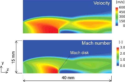
Figure 7. Pressure profiles along centerline of underexpanded air jet.
3.2. Analysis of water vapor discharging into sodium pool
The test analysis on water vapor discharging into liquid sodium was performed to confirm a capability of the numerical method and to compare the effect of two types of meshing approaches. The effect of use of the unstructured mesh must be investigated quantitatively through a comparison with experimental results. The work on numerical analysis of sodium–water reaction experiment conducted in the domain including heat transfer tube bundle will be performed in our future researches. The hypothetical domain shown in (a) was constructed for this test analysis. The domain consists of the simulated horizontal heat transfer tube (target tube) and the discharging nozzle below the target tube. The domain was initially filled with the liquid sodium at the temperature of 470 °C. There is an 8-mm square-shaped inflow boundary at the upper end of the discharging nozzle. The water vapor at 470 °C and 10 MPa goes into the pool vertically from the inflow boundary with 100 m/s and the reacting flow impinges on the target tube. The liquid sodium flows in a vertical direction at 5 m/s from the bottom surface of the domain. The gas and liquid phases flow out from the top surface. The pressure at the top surface was set to be constant at 0.2 MPa. The temperature and the pressure conditions shown here is approximately same as the actual conditions of the SG. (b) shows the two different computational meshes applied to this analysis. The computational mesh A is constructed with rectangular cells. The surface of the target tube is modeled in a staircase pattern. On the other hand, the curvilinear surface of the target tube is simulated well in the computational mesh B constructed with triangular prism cells. The division number for each side of the rectangular domain conforms completely between the meshes A and B. The surface of the target tube is divided by roughly the same number of computational cells. In this case, the number of computational cells is 52,408 in the mesh A and 121,168 in the mesh B.
Figure 8. Computational domain for water vapor discharging into sodium pool.
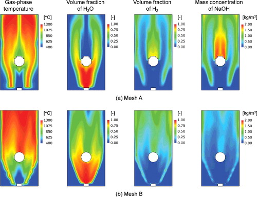
shows variation of the distributions of the void fraction and the gas-phase velocity on a vertical plane. This figure compares the numerical results under the two meshes. The numerical results show that the gas-phase goes upward around the target tube. The target tube in a staircase pattern increases the effect as an obstacle in the flow compared to that in the unstructured mesh. Therefore, the gas-phase velocity near the tube surface is relatively low at 0.15 seconds in the mesh A. The void fraction at the upper side of the target tube is also different between the meshes A and B at 0.15 seconds. shows the instantaneous distributions of the gas-phase temperature, the volume fraction of water vapor, the volume fraction of hydrogen, and the mass concentration of NaOH at 0.15 seconds. The volume fraction of water vapor is almost 1 above the discharging nozzle in both the meshes A and B. In the same region, the gas-phase temperature is relatively low due to the existence of the unreacted water vapor. The water vapor is used in chemical reaction with its rising. Instead, the reaction products, hydrogen and NaOH, appear and become the main species of the gas phase. The high-temperature region is formed around the unreacted water vapor and above the target tube due to the chemical reaction. At the upper side of the target tube, the significant difference of the distributions of the chemical species appears between the meshes A and B. The flow of water vapor is almost completely separated by the target tube in the mesh A while the water vapor flows behind the target tube in the mesh B. From this, the gas-phase temperature at the upper side of the target tube in the mesh B is higher than that in the mesh A. The temperature distribution around the target tube is extremely important in predicting occurrence of the tube failure propagation since the material strength of the tube depends on the ambient fluid temperature. The use of the unstructured mesh is highly effective on the prediction. The gas-phase temperature increased up to about 1270 °C by the chemical reaction in the mesh B. Kurihara et al. [Citation15] measured the temperature distribution in the experiment on discharging of the water vapor in the liquid sodium pool in which the heat transfer tube bundle exists and reported that the peak temperature increased over 1200 °C. The numerical results demonstrate that the developed SERAPHIM code has a capability to predict the peak temperature formed by the sodium–water chemical reaction. Numerical analysis of the experiment on sodium–water reaction phenomenon with multi-tube configuration by using the unstructured mesh-based SERAPHIM code will be performed to enhance its reliability in our future work.
Figure 9. Numerical results of water vapor discharging into sodium pool (variation of void fraction and gas-phase velocity).
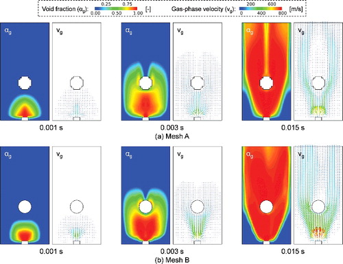
Figure 10. Numerical results of water vapor discharging into sodium pool (gas-phase temperature and chemical species at 0.015 seconds).
4. Conclusion
The unstructured mesh-based numerical method was developed and introduced into the SERAPHIM code to advance a numerical accuracy for the complex-shaped domain including multiple heat transfer tubes. The validity of the numerical method was investigated through some numerical analyses. First, it was demonstrated that the proposed governing equations and the solution method considering compressibility could represent underexpanded jets, which is one of the most basic phenomena under tube failure accident. The numerical results reproduced a well-known structure of the underexpanded jet. The calculated pressure showed good agreement with the experimental data. In the numerical analysis of water vapor discharging into liquid sodium, the SERAPHIM code could calculate the temperature field formed by the multiphase flow with chemical reaction. The use of the unstructured mesh is highly effective in predicting the distributions of the fluid temperature around the target tube. The calculated peak temperature agreed with the previous experimental knowledge. The proposed numerical method has a capability to evaluate the sodium–water reaction phenomenon.
Disclosure statement
No potential conflict of interest was reported by the authors.
References
- Takata T, Yamaguchi A. Numerical approach to the safety evaluation of sodium-water reaction. J Nucl Sci Technol. 2003;40:708–718.
- Takata T, Yamaguchi A, Fukuzawa K, et al. Numerical methodology of sodium-water reaction with multiphase flow analysis. Nucl Sci Eng. 2005;150:221–236.
- Takata T, Yamaguchi A, Uchibori A, et al. Computational methodology of sodium-water reaction phenomenon in steam generator of sodium-cooled fast reactor. J Nucl Sci Technol. 2009;46:613–623.
- Uchibori A, Watanabe A, Ohshima H. Development of a numerical method for compressible multi-phase flows including highly underexpanded jets. Proceedings of the 13th International Topical Meeting on Nuclear Reactor Thermal Hydraulics (NURETH-13); 2009 Sep 27–Oct 2; Kanazawa, Japan, Tokyo (Japan): Atomic Energy Society of Japan; 2009; N13P1189.
- Uchibori A, Watanabe A, Ohshima H. Numerical analysis of supersonic gas jets into liquid pools with or without chemical reaction using the SERAPHIM program. Nucl Eng Des. 2012;249:35–40.
- Uchibori A, Ohshima H. Development of a mechanistic evaluation method for wastage environment under sodium-water reaction accident. Proceedings of the 16th International Topical Meeting on Nuclear Reactor Thermal Hydraulics (NURETH-16); 2015 Aug 30–Sep 4; Chicago, IL. La Grange Park (IL): American Nuclear Society; 2015. NURETH-16-13542.
- Kuehner JP, Dutton JC, Rucht RP. High-resolution N2 CARS measurements of pressure, temperature, and density using a modeless dye laser. Proceedings of 22nd AIAA Aerodynamic Measurement Technology and Ground Testing Conference; 2002 Jun 24-26; St. Louis, MO. Reston (VA): American Institute of Aeronautics and Astronautics; 2002, AIAA 2002-2915.
- Woodmansee MA. Experimental measurements of pressure, temperature, and density using high-resolution N2 coherent anti-Stokes Raman scattering [dissertation]. Urbana (IL): University of Illinois at Urbana-Champaign; 1999.
- Benedict M, Webb GB, Rubin LC. An empirical equation for thermodynamic properties of light hydro-carbons and their mixtures methane, ethane, propane and n-butane. J Chem Phys. 1940;8:334–345.
- Autruffe MI, Wilson GJ, Stewart B, et al. A proposed momentum exchange coefficient for two-phase modeling of sodium boiling. Proceedings of the International Meeting on Fast Reactor Safety Technology; 1979 Aug 19–23; Seattle, WA, La Grange Park (IL): American Nuclear Society; 1979. p. 2512–2521.
- Rivard WC, Torrey MD. Numerical calculation of flashing from long pipes using a two-fluid model. Los Alamos (NM): Los Alamos Scientific Laboratory of the University of California; 1976. (Los Alamos Scientific Laboratory Report; LA-NUREG-6330-MS).
- Darwish MS, Moukalled F. TVD schemes for unstructured grids. Int J Heat Mass Transfer. 2003;46:599–611.
- Hirt CW, Cook JL. Calculating three-dimensional flows around structures and over rough terrain. J Comput Phys. 1972;10:324–340.
- Matsumoto Y, Murai Y. Numerical simulation of bubble plume in a tank with free surface. JSMET 1995;61:2818–2825. Japanese.
- Kurihara A, Shimoyama K, Hamada H, et al. Research on sodium-water reaction phenomena in steam generator of sodium-cooled commercial fast reactor (2) sodium-water reaction experiment under intermediate water leak condition. Proceedings of the 2011 Annual Meeting of Atomic Energy Society of Japan; 2011 Mar 28–30; Fukui, Japan. Tokyo (Japan): Atomic Energy Society of Japan; 2011. H21. Japanese.