
 ?Mathematical formulae have been encoded as MathML and are displayed in this HTML version using MathJax in order to improve their display. Uncheck the box to turn MathJax off. This feature requires Javascript. Click on a formula to zoom.
ABSTRACT
A neutron guide system for neutron resonance spin echo spectrometers has been constructed at BL06 of the Japan Proton Accelerator Research Complex, Materials and Life Science Experimental Facility. The spectrometers consist of two types of neutron spin echo instruments, a modulated intensity by zero effort instrument (MIEZE) and a neutron resonance spin echo instrument (NRSE), to cover a wide energy range for various sample environments. A neutron beam from the moderator is deflected by supermirror neutron guides, split, and separately guided into the MIEZE and NRSE. The characteristic wavelengths of the neutron guide tube for the MIEZE and NRSE are 2.9 and 4.9 Å, respectively. The cross sections of the exit of the MIEZE and NRSE guides are 15 mm × 50 mm and 30 mm × 50 mm, respectively. The neutronics and shielding design were optimized by using the heavy ion transport code system (PHITS), and the absolute average neutron fluxes at the exits of the MIEZE and NRSE guides are estimated to be 2.7 × 10⁸ and 6.9 × 10⁸ n/cm2/s/MW, respectively. The measured fluxes of the MIEZE and NRSE neutron guides are 0.56 and 0.95 times the calculated values, respectively.
1. Introduction
Neutron scattering is a very powerful study tool in material science, life science, and industrial applications. The neutron spin echo (NSE) technique [Citation1–3] is a unique spectroscopic method to investigate the slow dynamics of molecules and molecular assemblies. It measures the intermediate scattering function S(Q,τ) directly, where Q and τ are the momentum transfer of neutrons and Fourier time, respectively, with very high neutron energy resolution independent of the resolution of incident neutron beam. With a pulsed neutron source, the NSE technique makes it possible to scan a wide spatiotemporal space very efficiently because both Q and τ depend on neutron wavelength λ, which can be evaluated by the time-of-flight (TOF) technique. The Materials and Life Science Experimental Facility (MLF) at the Japan Proton Accelerator Research Complex (J-PARC) is one of the major neutron/muon experimental facilities in the world. Kyoto University and the High Energy Accelerator Research Organization (KEK) are jointly installing two types of NSE spectrometers at BL06 at the MLF, that is, a neutron resonance spin echo instrument (NRSE) [Citation4] and a modulated intensity by zero effort instrument (MIEZE) [Citation5]. The typical scientific target for the NRSE is to explore slow dynamics in soft matter, which requires a high-energy resolution with a small sample, and the typical target for the MIEZE is hard matter, which requires a medium-energy resolution with flexible sample environment, including a strong magnetic field. With the two spectrometers, it is possible to cover a wide spatiotemporal range with various sample environments. We named the spectrometers ‘VIN ROSE’ (VIllage of Neutron ResOnance Spin Echo spectrometers), which will spawn a new field of spectroscopic methods to investigate the slow dynamics of nanostructures in various materials. Both the NRSE and MIEZE make use of neutron resonance spin flippers and state-of-the-art neutron optics, which enabled us to design and install compact and multiple spectrometers in a narrow space. In this paper, we report the design and performance of a supermirror neutron guide system for the VIN ROSE.
2. The concept of the BL06 beamline design
The Japan Spallation Neutron Source (JSNS) located at the MLF operates with 3 GeV and 1 MW pulsed proton beams, and it provides pulsed neutrons within the highest intensity category available in the world [Citation6,Citation7]. The JSNS produces fast and slow neutrons in the energy range from GeV to sub-meV with three types of supercritical hydrogen moderators, viz. coupled, decoupled, and poisoned moderators, surrounding a mercury spallation target. The coupled moderator produces the highest neutron intensity with a broad pulse width, the decoupled moderator produces low intensity with short pulse width, and the poisoned moderator produces the lowest intensity with the shortest pulse width. For the TOF technique, the pulse width is very important since it determines the resolution of neutron wavelength. For the VIN ROSE, we have chosen to use the BL06, the coupled moderator beamline, because although the requirement for wavelength resolution is not high, a high neutron intensity is strongly desired. An important specification of an NSE spectrometer is determined by the Fourier time, which is proportional to the third power of neutron wavelength [Citation1,Citation4,Citation5]. As a longer Fourier time means a higher energy resolution, the beamline of the VIN ROSE should be designed to transport cold neutrons efficiently. Owing to the high-intensity pulsed neutron beam, the VIN ROSE will be capable of efficiently scanning a wide spatiotemporal (Q-τ) region using the TOF technique. In general, fast neutrons and gamma rays are present as a strong background with neutron generation. In a pulsed neutron source, such as at the J-PARC, the detection time of slow neutrons is several milliseconds after the time of neutron generation, which is long enough to avoid the background. Therefore, one of the big advantages of using a pulsed neutron source is the very low background, especially for slow neutrons, obtained using the TOF technique. It is also possible to conduct a more precise measurement by using the TOF technique [Citation8]. Furthermore, we are developing ellipsoidal supermirrors for focusing neutrons on a sample position that is several millimeters in size [Citation9,Citation10]. The focusing mirror is necessary for a higher energy resolution of the NRSE [Citation3,Citation11]. It also enables us to measure the weak scattering intensity of the small sample with a higher energy resolution.
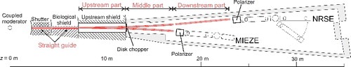
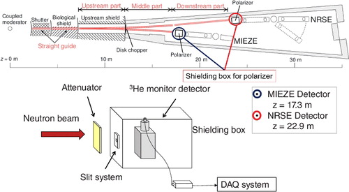
By taking the concept and requirements of the spectrometers into consideration, we designed the neutron transportation optics at the BL06 as shown in . For NSE, fast neutrons are not only useless, but are also a source of neutron background, and create unexpected radiation products. As the fast neutrons have strong penetration power, powerful shielding is required to stop them. Note that the area for the BL06 is fan-shaped with a central angle of 8.2°, which is less than that of other beamlines for a coupled moderator. For constructing two spectrometers in the narrow area, we constructed two curved supermirror guide tubes with a radius of curvature of 140 m to transport only cold neutrons and to create sufficient experimental space. The MIEZE is more compact and requires a wider Q region than the NRSE. Thus, the MIEZE is installed upstream from the NRSE, and the guide of the MIEZE is shorter than that of the NRSE. The detailed design of the guide tubes will be described in the next section.
Figure 1. Schematic top view of VIN ROSE beam line at BL06 at J-PARC/MLF. The neutron guide parts are described in red double lines. There are straight guides in the shutter and biological shields. The two and three guide parts are installed for MIEZE and NRSE, respectively.
3. Beam transportation optics and shielding
In , the letter z indicates the distance from the source. The shutter and biological shield are located at a distance of z = 2.3–4.3 m and z = 4.3–7.2 m, respectively, in which there is a square beam duct with 10 cm × 10 cm. It is better for a smaller radiation dose rate downstream of the experimental area to reduce the effective size of the beam duct. However, it was very difficult to locate the two curved guides precisely within a short time in such narrow and high irradiation space. We also tried to avoid unexpected loss of beam intensity owing to misalignment of the neutron guides. Thus, we have chosen a straight 2Qc NiC/Ti supermirror guide with an inner cross section of 93 mm × 93 mm to transport cold neutrons with a large divergent angle, where mQc indicates the maximum critical angle that is m times the critical angle of natural nickel. The inner cross section was as large as possible to achieve longer wavelength neutron transportation. This choice was similar to BL05 (Neutron Optics and Physics beamline) at the MLF [Citation12].
All neutron supermirrors were deposited on silicon substrates using an ion beam sputtering machine (KUR-IBS) at the Kyoto University Research Reactor Institute (KURRI) [Citation13], because the silicon wafer is tough enough for high irradiation fields. Furthermore, the surface condition, such as surface roughness and cleaning level, is well controlled and the adhesion force to the substrate is, in general, larger than that to a glass substrate. For the 2Qc NiC/Ti supermirror guide, we used commercial polished silicon (111) wafers with a thickness of 3 mm. The Young's modulus of the silicon wafer is almost double that of float glass. The deflection of the supermirror increases with the m value owing to the internal compressive stress of the supermirror. The silicon wafer was thick enough to remain flat even for the m = 3 supermirror coating without any special fixation.
There is a void space of 1 × 1.7 m2 at z = 7–12 m in each shield at the MLF. From the position of z = 7.3 m after the straight guide, the neutron beam is separated by supermirror curved guides for the MIEZE and NRSE. By using the curved guide tube, fast neutrons and gamma rays from the source are eliminated by shielding materials surrounding the supermirrors. The total length of the curved guides for the MIEZE and NRSE is 9.5 m. To satisfy the requirements of both a reasonable construction cost and positional accuracy of each supermirror, the guide tubes are separated into two parts, namely, the upstream part (z = 7.3–12 m) and the middle part (z = 12.3–17.1 m). Only for the NRSE, the straight guide with a length of 5.4 m, is the downstream part (z = 17.3–22.7 m) extended. The length was determined by ordinary commercial base iron steel and the supermirrors were fixed at proper positions on the surface of a mirror-finished steel plate with an accuracy of 10 uμm by a Japanese company. It is useful to not only achieve positional accuracy of the guides but also to save installation time and cost. This technical concept has been examined with a supermirror guide at the KURRI, to our knowledge, which is the world's first full-fledged supermirror guide tube [Citation14]. The radius of curvature of both the guides is 140 m and the widths of the MIEZE and NRSE guides are 15 and 30 mm, respectively. The width was optimized to obtain the required slow neutron beam without fast neutrons [Citation15,Citation16]. The m values of the supermirrors of the guides are chosen to match the characteristic wavelength of the wavelength band required for the spectrometers. The characteristic wavelength λc is given by the equation , where w and R are the width and radius of curvature of the guide, respectively. For the MIEZE, 3Qc NiC/Ti supermirrors are required to make the characteristic wavelength 2.9 Å and having a maximum intensity at the moderator. For the NRSE, the shortest wavelength is limited by the acceptable neutron wavelength of the ellipsoidal focusing mirrors, λ > 6 Å. To transport cold neutrons with a larger divergent angle for the focusing mirrors, we selected the characteristic wavelength as 4.9 Å, which is a comprehensive safety margin for neutron transportation, and NiC/Ti supermirrors of 2.5Qc to 4Qc were used for the NRSE guide tube (the supermirrors in the last several guide elements of the downstream part are gradually changed up to 4Qc supermirrors).
Because the curvature is relatively steep, the curve is approximated by a polygonal from a manufacturing perspective, and the length of a typical guide element is 300 mm. The typical size of a silicon substrate for the side of an element for the MIEZE and NRSE is 70 mm × 149.5 mm × 3 mm and 140 mm × 149.5 mm × 3 mm, respectively. Those for the top and bottom of the element are for the MIEZE and NRSE, respectively, 14 mm × 149.5 mm × 0.725 mm and 29 mm × 149.5 mm × 0.725 mm. The determination of these sizes was not only due to the reason described above but also inspired by the production performance of the KUR-IBS [Citation12,Citation17]. The MIEZE guide is a simple rectangular curved guide. In contrast, in the NRSE beamline for smaller sample sizes with neutrons with a longer wavelength, all vertical component of the three parts have a polygonal elliptical shape in which major and minor axis are 11,800 and 60 mm, respectively. The horizontal component of the downstream part is also polygonal elliptically shaped in which major and minor axis are 3500 and 25 mm, respectively. The detailed parameters of each guide are shown in .
Table 1. Design parameters of neutron guides for the MIEZE and NRSE at J-PARC/MLF.
The band choppers of the MIEZE and NRSE are located between the upstream and middle guide parts to select the required neutron wavelength. The band chopper consists of aluminum disks covered by Gd2O3 paint and the apertures of the MIEZE and NRSE are 162° and 126°, respectively. Before the choppers (z < 12 m), the gap between the MIEZE and NRSE was filled as much as possible with iron shielding without clearance in order to eliminate fast neutrons and gamma rays (in this case, thin polished silicon wafer is a good substrate to reduce the clearance). To reduce the number of fast neutrons, the supermirrors in the upstream part are covered by iron blocks, those in the middle part are covered by B4C rubber sheets and iron blocks, and those in the downstream part are covered by B4C rubber sheets and iron or lead blocks to create as large an experimental and maintenance space as possible. In addition, a detachable small straight guide was placed between the middle and downstream parts for the NRSE beamline (z = 17.1–17.3 m) to reduce the dose rate. All neutron guides except for the detachable small guide are placed in a vacuum. The vacuum windows are composed of an aluminum alloy (A5083) and the thicknesses are 1.5 and 1 mm for the straight guide (z = 2.3–7.2 m) and curved guides (z > 2.3 m), respectively.
4. Numerical simulation of the BL06 supermirror guide system
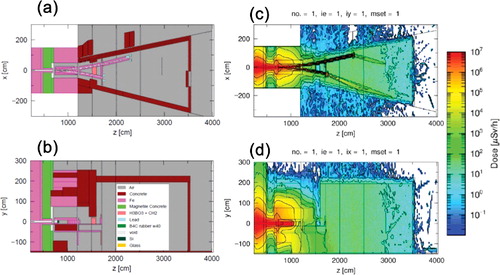
The JSNS is one of the first facilities in the world to fully adopt a numerical simulation code for neutronics design [Citation18]. The neutron intensity and irradiation dose rate of the BL06 beamline were also evaluated with the particle and heavy ion transport code system 2.30 (PHITS) before construction [Citation19]. We not only estimated the guide design but also optimized the thickness of the walls surrounding the entire BL06 experimental area. The nuclear data JENDL-4.0 and BL06 MLF's public neutron source spectrum at 1 MW were used [Citation20,Citation21]. shows the BL06 simulation geometry and shielding, and the radiation dose rate calculated by the PHITS. In the PHITS, we used a variance reduction technique, called ‘duct source option,’ to simulate long supermirror guides at BL06. The dose rate at the side boundary of the BL06 experimental area should be less than 10 uμSv/h and that at the backward boundary should be less than 0.1 uμSv/h in the case of 1 MW operation. These results fulfill the legal requirements and the more strict rules of the MLF to prevent radiation hazards. The polarizing systems, which consist of a Fe/SiGe supermirror polarizer [Citation22] and 4-quadrant slits in a shielding box made of B4C rubber and lead, are located at the guide exits of the NRSE and MIEZE. In the polarizer shielding box, the maximum apertures of the slit of the MIEZE and NRSE are limited to be less than 5 mm × 20 mm and 10 mm × 10 mm, respectively. Here, the sizes of the apertures are much smaller than those of the cross sections of the guide exits. This is for commissioning the experiment while keeping the dose rate as low as possible. The aperture sizes are sufficient for the measurement because the typical sample sizes for the MIEZE and NRSE are 5 mm × 20 mm and 5 mm × 5 mm. On the other hand, we need a big enough margin to adjust the optical axis. An NSE spectrometer is very sophisticated and there are many devices in comparison to other neutron spectrometers. Furthermore, the VIN ROSE is a new challenge in NSE spectrometer development worldwide and some devices are under development, such as large ellipsoid focusing mirrors and resonance spin flippers. At the VIN ROSE, the cross section of the guide exit should be larger than the slit aperture to ensure adjustment allowance for improvement of the devices.
Figure 2. PHITS geometry with (a) horizontal (xz)-plane at y = 0 and (b) vertical (yz)-plane at x = 0 in the BL06 shielding design. The total (neutron and photon) dose rate maps, (c) horizontal (xz)-plane at y = 0 and (d) vertical (yz)-plane at x = 0, were calculated on the PHITS geometry.
shows evaluated neutron spectra at the source, the guide exit of the MIEZE (z = 17.1 m) and NRSE (z = 22.7 m), respectively. The total number of events with neutron energy less than 0.1 eV was 1.88 × 10⁶. The intensity of the fast neutrons is evaluated to be 5 × 10⁻⁷ times that of the slow neutrons at the guide exits. The neutron wavelength having the maximum intensity at the guide exit of the MIEZE was 3.6 Å and at that of the NRSE 4.7 Å. The peak intensities of the MIEZE and NRSE were expected to be 1.7 × 10⁸ and 1.6 × 10⁸ n/cm2/s/Å/MW, respectively. In the PHITS, the reflectivity of a mQc supermirror is given by the following equation:
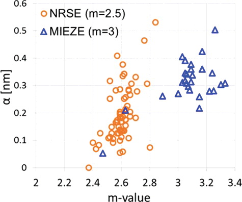
where R0 = 0.99 and Qc = 0.0217 Å−1. The parameters W and α are fitting parameters. The typical value for W was 0.003 Å−1. α is a decay coefficient from the total reflection and it represents the performance of the mQc supermirror. We fabricated all neutron supermirrors at the BL06 and measured reflectivities of these supermirrors at the SOFIA reflectometer located at BL16 in MLF [Citation23, 24Citation24]. shows plots of the parameter α of supermirrors for the MIEZE and NRSE as a function of m values. Most of the supermirrors were well fabricated but a few ones were not so good, and the supermirrors that did not meet the requirements were eliminated. Good supermirrors, which had high reflectivities and m values, were positioned at the garland side of each guide to increase neutron intensity, because the number of reflections of transported neutrons at the garland side of the guide is larger than that at the other (zigzag) side. Here, there are two types of reflection of transported neutrons. One is the garland reflection in which the reflection angle is small and the transported neutrons never touch the inner (zigzag) side of the curved neutron guide. The other is the zigzag reflection in which the reflection angle is large and the transported neutrons touch the zigzag side. The PHITS simulation was run with the measured reflectivity of the placed supermirrors. More detailed considerations such as the divergent angle of wavelength-dependence and the effect of misalignment of the supermirrors are described elsewhere [Citation15].
Figure 3. Calculated neutron spectra of wide energy range at the source, the guide exit of the MIEZE (z = 17.1 m) and NRSE (z = 22.7 m), respectively. (b) Calculated neutron spectra of slow energy range at the guide exit of the MIEZE (z = 17.1 m) and NRSE (z = 22.7 m) as a function of wavelength with narrow energy range.
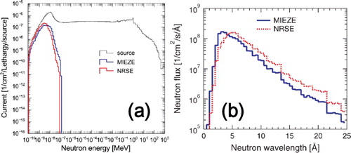
Figure 4. PHITS parameter α of measured NiC/Ti supermirror for the MIEZE and NRSE as a function of the m value.
5. Construction and evaluation of the BL06 supermirror guide system
The three guide parts, the upstream, middle, and downstream parts, were installed in the BL06 area at the MLF. The relative positional accuracy among the three parts was within 0.1 mm. A neutron activation analysis of a gold foil is used to determine the absolute neutron intensity at the guide exits. Gold foils with an effective size of 10 mm × 10 mm were placed at central positions of the exits of the MIEZE and NRSE guides; this was necessary for accurate estimation of the neutron flux to measure the wavelength distribution. We measured TOF spectra in a polarizer shielding box in the vicinity of the guide exits of the MIEZE (z = 17.3 m) and NRSE (z = 22.9 m), as shown in . Here, most of the slow neutrons are stopped at the polarizer shielding box to obtain the required polarizing neutron beam. The polarizer can easily be replaced depending on the development. In order to measure the TOF spectra of the guides, a He-3 monitor detector, with an efficiency of 10−4, was set in the polarizing shielding box instead of the polarizer. The efficiency was almost minimum because of the effect of beta decay from the aluminum window of the detector. The required momentary counting rate was very high and the efficiency was not low enough to measure the TOF spectra. Therefore, we used borosilicate glass as an attenuator to adjust the counting rate. The true shape of the TOF spectrum as a function of wavelength is given by the equation I0(λ)∝IOBS(λ)exp (∑Aλ)/λ, where λ, IOBS(λ) and ΣA are the neutron wavelength, the measured TOF spectrum, and the attenuation factor of the borosilicate glass, respectively. The attenuation coefficient of the borosilicate glass was measured precisely at the SOFIA reflectometer and estimated to be ΣA = 0.2055t (Å−1), where t is the thickness of the borosilicate glass in millimeters. A more detailed correction for the activation analysis is also described elsewhere [Citation15].
Figure 5. Schematic experimental setup of TOF spectrum and absolute neutron flux measurement for the performance evaluation of the VIN ROSE guide system. Detectors were located at the vicinities of the guide exits of the MIEZE (z = 17.3 m) and NRSE (z = 22.9 m) guides, respectively.
(a,b) shows the TOF spectra in the vicinities of the guide exits of the MIEZE and NRSE, respectively, with a proton beam power of 0.275 MW. The detection area of the TOF measurement was 10 mm × 10 mm, the same as that of gold foil measurement. The TOF spectrum of the MIEZE guide goes up to a wavelength of 12.5 Å. This was measured by connecting the TOF data with three different phases of the disk choppers. The TOF spectrum of the NRSE guide goes up to a wavelength of 9.5 Å, measured by connecting the TOF data with two different phases. The spectra of the MIEZE and NRSE guides were extrapolated by the power functions Φ(λ)/dλ∝λ− 4.45 and Φ(λ)/dλ∝λ− 3.27, respectively. The maximum thicknesses of the borosilicate glass for the TOF measurement of the MIEZE and NRSE guides were 6 and 4 mm, respectively. With the spectra and gold foil activation measurement, the absolute neutron fluxes at central positions of the exits of the MIEZE and NRSE guides were estimated to be 0.73 × 10⁸ and 1.9 × 10⁸ n/cm2 /s, respectively. The neutron fluxes at the MIEZE and NRSE from the PHITS calculation, including the measured reflectivity of supermirror, were 1.3 × 10⁸ and 2.0 × 10⁸ n/cm2 /s with the proton beam power of 0.275 MW, respectively. Those estimated values for the MIEZE and NRSE were 0.56 and 0.95 times, respectively, in comparison with the PHITS calculation. The performance parameters of the MIEZE and NRSE guides are shown in .
Figure 6. Neutron spectrum of total cross section at the vicinities of the guide exits of the (a) MIEZE (z = 17.3 m) and (b) NRSE (z = 22.9 m). The blue bronken and red solid lines are calculated and measured, respectively. The light red solid lines from (a) 12.5 Å and (b) 9.5 Å were extrapolated with a power function of neutron wavelength.
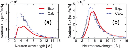
Table 2. Performance parameters of the neutron guide system for VIN ROSE at the BL06 at the J-PARC/MLF.
The measured neutron flux of the NRSE guide was well reproduced by the PHITS calculation within the error of activation measurement. The measured TOF spectrum was slightly shifted to the longer wavelength side as compared to the PHITS calculation, as shown in (b). The wavelength of peak intensity was measured as 5.5 Å. For wavelengths longer than 6 Å, the measured intensity was about 10% higher than the calculated one. On the other hand, the measured intensity of the MIEZE guide was almost half that from the calculation. In (a), a depression around a wavelength of 4 Å, near to the peak intensity, can be seen and it gives rise to two peaks at 4.8 and 3.6 Å. For wavelengths longer than 6 Å, the measured intensity was about 35% smaller than the calculated one.
We also measured TOF spectra as a function of the position dependence of the guide exit. shows the calculated and measured intensity maps and TOF spectra at three typical positions of the MIEZE guide exit. These measured and calculated detection areas were 5 mm × 10 mm and 2 mm × 2 mm, respectively. The measured neutron intensity at the garland reflection side (+x direction) is a bit higher than that at the zigzag reflection side (−x direction). The effect of the garland reflection is more clearly shown in the PHITS calculation. For wavelengths longer than 6 Å, the measured flux at the center and zigzag sides is about 35% smaller than the calculation, the same as in (a). The measured flux at the garland side is about 50% smaller than the calculation. In (a–c), the measured fluxes are consistent with the PHITS calculation multiplied by the scaling factors except for the peak intensity around 4 Å. Regardless of the local position at the MIEZE guide exit, the depression of the peak intensity is observed the same as in (a). The position dependence of the measured flux is comparatively uniform in comparison with the PHITS calculated flux. It is known that neutrons with wavelength of approximately 4 Å were attenuated, owing to Bragg scattering of oriented grains of aluminum alloy. There is no estimation for such a grain effect with the PHITS simulation. Some intensity loss is caused by the windows. However, the expected loss intensity is, in general, much smaller than the measured loss.
Figure 7. Total neutron intensity maps and TOF spectra as a position-dependence at the vicinity of the MIEZE guide exit (z = 17.3 m) at 0.275 MW operation. The TOF spectra were measured at three positions: (a) zigzag (x = −5, y = 0 [mm]), (b) center (x = 0, y = 0 [mm]) and (c) garland (x = +5, y = 0 [mm]) sides at the measured map. The detection area of the TOF measurement was 5 mm × 10 mm.
![Figure 7. Total neutron intensity maps and TOF spectra as a position-dependence at the vicinity of the MIEZE guide exit (z = 17.3 m) at 0.275 MW operation. The TOF spectra were measured at three positions: (a) zigzag (x = −5, y = 0 [mm]), (b) center (x = 0, y = 0 [mm]) and (c) garland (x = +5, y = 0 [mm]) sides at the measured map. The detection area of the TOF measurement was 5 mm × 10 mm.](/cms/asset/2f6930fb-e951-4a28-9329-22ecf51422f4/tnst_a_1359699_f0007_oc.jpg)
Figure 8. TOF spectra at the vicinity of the MIEZE guide exit (z = 17.3 m) were measured at three positions: (a) zigzag (x = −5, y = 0 [mm]), (b) center (x = 0, y = 0 [mm]) and (c) garland (x = +5, y = 0 [mm]) sides at the measured map as shown in . The neutron fluxes calculated at the (a), (b) and (c) positions were multiplied by 0.65, 0.65 and 0.5, respectively.
![Figure 8. TOF spectra at the vicinity of the MIEZE guide exit (z = 17.3 m) were measured at three positions: (a) zigzag (x = −5, y = 0 [mm]), (b) center (x = 0, y = 0 [mm]) and (c) garland (x = +5, y = 0 [mm]) sides at the measured map as shown in Figure 7. The neutron fluxes calculated at the (a), (b) and (c) positions were multiplied by 0.65, 0.65 and 0.5, respectively.](/cms/asset/1bb05141-635d-4b0c-a3b3-be48363a1c9b/tnst_a_1359699_f0008_oc.jpg)
shows the calculated and measured intensity maps and TOF spectra at three typical positions of the NRSE guide exit. The measured neutron intensity at the garland side (−x direction) was also a bit higher than that at the zigzag side (+x direction), although the calculated intensity is uniform. In (a), the spectrum at the garland side is consistent with that of the PHITS calculation. At ranges of a longer wavelength than 6 Å in (a–c), the measured spectra are consistent with those by the PHITS calculated one. The difference between measured and calculated fluxes becomes larger at the direction of zigzag side. Here, the detection area of the spectrum at was half the width of that at . As shown in a comparison of (b) and (b), the neutron flux depends on the local position since the downstream part is a focusing guide with a polygonal elliptical shape. The downstream part is a not curved guide and the average direction of the neutron beam from the middle guide part is maintained. There is a discrepancy of the calculation and the measurement although the absolute neutron flux and TOF spectrum at the central position of the exit of the NRSE guide is well reproduced by the PHITS calculation.
Figure 9. Total neutron intensity maps and TOF spectra as a position-dependence at the vicinity of the NRSE guide exit (z = 22.9 m) at 0.275 MW operation. The TOF spectra were measured at three positions: (a) garland (x = −10, y = 0 [mm]), (b) center (x = 0, y = 0 [mm]) and (c) zigzag (x = +10, y = 0 [mm]) sides at the measured map. The detection area of the TOF measurement was 5 mm × 10 mm.
![Figure 9. Total neutron intensity maps and TOF spectra as a position-dependence at the vicinity of the NRSE guide exit (z = 22.9 m) at 0.275 MW operation. The TOF spectra were measured at three positions: (a) garland (x = −10, y = 0 [mm]), (b) center (x = 0, y = 0 [mm]) and (c) zigzag (x = +10, y = 0 [mm]) sides at the measured map. The detection area of the TOF measurement was 5 mm × 10 mm.](/cms/asset/ef44c1dc-47ad-41b0-9dde-857acdcca8d3/tnst_a_1359699_f0009_oc.jpg)
There are two possible reasons for the discrepancy between the calculation and the measurement. The first possibility is a misalignment problem such as unexpected displacement of the three guide parts and a distortion of the supermirrors after the installation. When the sedimentation degrees of the three guide parts are large and they are different to each other, the discrepancy becomes larger with a smaller cross section of the neutron guide. Especially, when the middle part is only shifted to the BL05 side in the order of millimeters, the intensity at the garland side of the MIEZE guide is dramatically reduced and the trend of neutron flux at the NRSE guide can be explained qualitatively. However, we could not find a quantitative reason for the loss from something like misalignment of the guide system at the installation, counting loss of the detector, and mismeasurement of the activation analysis. The detailed simulation with the re-measurement of the guide geometry will be conducted during a maintenance of the guide system.
The second possibility is an intensity dependence on the divergent angle and wavelength at narrow area at the coupled neutron source. In the initial neutron source data for the PHITS simulation, angular distribution of the neutron intensity is assumed to be uniform. In other words, there is no information about neutron intensity for divergent angles or wavelength dependency in this neutron source data. The acceptable beam size and divergent angle for the MIEZE guide was much smaller than that for the NRSE guide. The local position on the moderator glanced at the MIEZE guide was a little different compared with that of the NRSE guide. The second possibility is expected to be solved with improvement of the PHITS calculation technique.
6. Concluding remarks
Kyoto University and KEK have jointly constructed a neutron guide system for the MIEZE and NRSE, also called ‘VIN ROSE,’ at BL06 of J-PARC/MLF. All neutron supermirrors were deposited on silicon substrates with the KUR-IBS and evaluated by reflectivity measurements using the SOFIA reflectometer. The characteristic wavelengths of the neutron guide tube for the MIEZE and NRSE are 2.9 and 4.9 Å, respectively. The cross sections of the exit of the MIEZE and NRSE guides are 15 mm × 50 mm and 30 mm × 50 mm, respectively. In the PHITS calculation, the intensity of fast neutrons from these guide exits is 5 × 10⁻⁷ times that of slow neutrons.
The measured absolute neutron fluxes at the central part of the guide exits of the MIEZE and NRSE are estimated to be 2.7 × 10⁸ and 6.9 × 10⁸ n/cm2/s/MW, respectively. The measured fluxes of the MIEZE and NRSE guides were 0.56 and 0.95 times the values obtained by PHITS calculation, respectively, including the measured reflectivity. The wavelengths of peak intensity of the MIEZE and NRSE were measured as 4.8 and 5.5 Å, respectively. In the NRSE guide, the measured fluxes and spectra are consistent with the PHITS calculated ones in the used wavelength range, λ > 6 Å. In the MIEZE guide, the local position dependence of the measured flux is uniform in comparison with the flux obtained through PHITS calculation, although the measured fluxes are smaller than the calculated ones.
In this study, we precisely compared the real and fully calculated performance of the BL06 guide system without any assumptions. The neutron source data were also fully calculated with the PHITS code and the BL06 neutronics and the shielding design was well optimized. It is, in general, difficult for a curved guide to achieve the calculated ideal intensity. The real performance at the BL06 guide system was well explained by the PHITS simulation within acceptable errors for use.
Acknowledgments
The authors gratefully acknowledge Dr Tetsuya Kai of the Japan Proton Accelerator Research Complex (J-PARC) for support in absolute neutron flux measurement and Mr Tatsuya Adachi and his colleagues of MEISHO KIKO Co. Ltd. for fruitful technical comments with regard to beamline construction. This work was supported by the approval of the Neutron Scattering Program Advisory Committee of the Institute of Materials Structure Science (IMSS), High Energy Accelerator Research Organization (KEK) [proposal number 2009S07], [proposal number 2009S08], [proposal number 2014S07]; the program Development of System and Technology for Advanced Measurement Analysis (SENTAN) from Japan Science and Technology Agency (JST); and the Photon and Quantum Basic Research Coordinated Development Program from the Ministry of Education, Culture, Sports, Science and Technology, Japan. The improvement of the multilayer fabrication technique was also supported by JSPS KAKENHI [grant number JP23360428]. The early neutron reflectivity measurements of the supermirrors were supported by the inter-university program for common use by the Japan Atomic Energy Agency (JAEA) and Kyoto University Research Reactor Institute (KURRI).
Disclosure statement
No potential conflict of interest was reported by the authors.
Additional information
Funding
References
- Mezei F. A new concept in polarized thermal neutron techniques. Z Phys. 1972;255:146–160.
- Mezei F, editor. Neutron spin echo, lecture notes in physics. Vol. 128. Heidelberg: Springer-Verlag; 1980.
- Mezei F, Pappas C, Gutberlet T. Neutron spin echo spectroscopy. Lecture Notes in Physics. Vol. 601. Berlin: Springer; 2003.
- Golub R, Gähler R. A neutron resonance spin echo spectrometer for quasi-elastic and inelastic scattering. Phys Lett A. 1987;123:43–48.
- Gähler R, Golub R, Keller T. Neutron resonance spin echo - a new tool for high resolution spectroscopy. Physica B. 1992;180–181:899–902.
- Maekawa F, Harada M, Oikawa K, et al. First neutron production utilizing J-PARC pulsed spallation neutron source JSNS and neutronic performance demonstrated. Nucl Instrum Methods A. 2010;620:159–165.
- Seto H, Itoh S, Yokoo T, et al. Inelastic and quasi-elastic neutron scattering spectrometers in J-PARC. Biochim Biophys Acta Gen Sub. 2017, 1861, 3651–3660.
- Oda T, Hino M, Kitaguchi M, et al. Pulsed neutron time-dependent intensity modulation for quasi-elastic neutron scattering spectroscopy. Rev Sci Instrum. 2016;57:105124.
- Guo J, Takeda S, Morita S, et al. New fabrication method for an ellipsoidal neutron focusing mirror with a metal substrate. Opt Express. 2014;22:24666–24677.
- Takeda S, Yamagata Y, Yamada LN, et al. Development of a large plano-elliptical neutron-focusing supermirror with metallic substrates. Opt Express. 2016;24:12478–12488.
- Kitaguchi M, Hino M, Kawabata Y, et al. High resolution NRSE spectrometer with 2D-focusing supermirrors. Physica B. 2011;406:2470–2472.
- Mishima K, Ino T, Sakai K, et al. Design of neutron beamline for fundamental physics at J-PARC BL05. Nucl Instrum Methods A. 2009;600:342–345.
- Hino M, Oda T, Kitaguchi M, et al. The ion beam sputtering facility at KURRI: coatings for advanced neutron optical devices. Nucl Instrum Methods A. 2015;797:265–270.
- Akiyoshi T, Ebisawa T, Kawai T, et al. Development of a supermirror neutron guide tube. J Nucl Sci Technol. 1992;29:939–946.
- Oda T. Japanese only. [dissertation]. Koyoto: Kyoto University; 2015.
- Oda T, Hino M, Kitaguchi M, et al. Numerical simulation of BL06 neutron beam line for VIN ROSE at J-PARC/MLF. Prog Nucl Sci Technol. 2014;4:214–217.
- Hino M, Oda T, Kitaguchi M, et al. Current status of BL06 beam line for VIN ROSE at J-PARC/MLF. Phys Proc. 2013;42:136–141.
- Harada M, Maekawa F, Oikawa K, et al. Application and validation of particle transport code Phits in design of J-PARC 1MW spallation neutron source. Prog Nucl Sci Technol. 2011;2:872–878.
- Sato T, Niita K, Matsuda N, et al. Particle and heavy ion transport code system, Phits, version2.52. J Nucl Sci Technol. 2013;50:913–923.
- Shibata K, Iwamoto O, Nakagawa T, et al. JENDL-4.0: a new library for nuclear science and engineering. J Nucl Sci Technol. 2011;48:1–30.
- http://j-parc.jp/researcher/MatLife/ja/instrumentation/. Japanese, The public neutron source spectrum at J-PARC/MLF with the proton beam power of 1MW.
- Hino M, Hayashida H, Kitaguchi M, et al. Development of large-m polarizing neutron supermirror fabricated by using ion beam sputtering instrument at KURRI. Physica B. 2006;385–386:1187–1189.
- Yamada NL, Torikai N, Mitamura K, et al. Design and performance of horizontal type neutron reflectometer SOFIA at J-PARC/MLF. Eur Phys J Plus. 2011;126:108(1–13). [24] Mitamura K, Yamada NL, et al. . 2013;45:100-108
- Mitamura K, Yamada NL, et al. Novel neutron reflectometer SOFIA at J-PARC/MLF for in-situ soft-interface characterization. Polymer J. 2013;45:100–108.