 ?Mathematical formulae have been encoded as MathML and are displayed in this HTML version using MathJax in order to improve their display. Uncheck the box to turn MathJax off. This feature requires Javascript. Click on a formula to zoom.
ABSTRACT
A unified resonance self-shielding method, which can treat general sub-divided fuel regions, is developed for lattice physics calculations in reactor physics field. In a past study, a hybrid resonance treatment has been developed by theoretically integrating equivalence theory and ultra-fine-group slowing-down calculation. It can be applied to a wide range of neutron spectrum conditions including low moderator density ranges in severe accident states, as long as each fuel region is not sub-divided. In order to extend the method for radially and azimuthally sub-divided multi-region geometry, a new resonance treatment is established by incorporating the essence of sub-group method. The present method is composed of two-step flux calculation, i.e. ‘coarse geometry + fine energy’ (first step) and ‘fine geometry + coarse energy’ (second step) calculations. The first step corresponds to a hybrid model of the equivalence theory and the ultra-fine-group calculation, and the second step corresponds to the sub-group method. From the verification results, effective cross-sections by the new method show good agreement with the continuous energy Monte-Carlo results for various multi-region geometries including non-uniform fuel compositions and temperature distributions. The present method can accurately generate effective cross-sections with short computation time in general lattice physics calculations.
1. Introduction
Resonance self-shielding treatment [Citation1] is an important part for the lattice physics calculations in reactor physics field. Accurate treatment of 238U wide resonance cross-sections and their influences on flux depressions is a key issue to guarantee a sufficient prediction accuracy of criticality and reactivity coefficients for commercial LWR (light water reactor) core analysis.
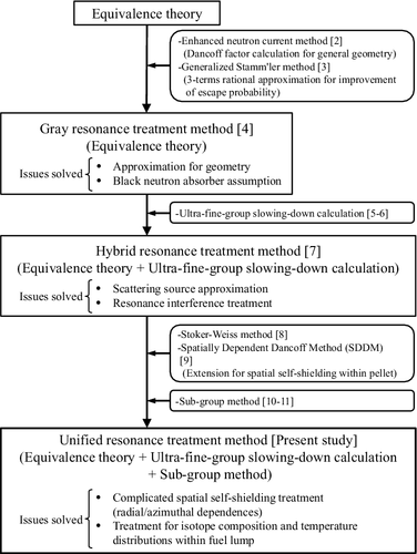
In order to establish a practical resonance treatment method, the effective cross-section is required to be generated with short computation time, while keeping its sufficient accuracy. In the past studies conducted by the authors, many of the technical issues have been solved to establish a sophisticated resonance treatment. A brief summary and the development history of the past and present studies are shown in [Citation2–11]. In the present study, a unified resonance treatment method is developed to obtain the sufficient accuracy for effective cross-sections without a direct heterogeneous ultra-fine-group calculation. As shown in , treatment of the complicated spatial self-shielding effect for radially and azimuthally sub-divided multi-region geometry within each fuel rod is addressed in the present paper.
In the first technical achievement by the authors [Citation4], approximation for geometry and black neutron absorber assumption in the equivalence theory [Citation1] are solved. Several spatial effects in a lattice physics theory (i.e. heterogeneous effect between fuel and non-fuel regions, shadowing effect due to the neighboring fuel rods, and irregular lattice effect by the local water enriched regions) can be incorporated into the pin-by-pin rational coefficients. The flux response as a function of macroscopic total cross-sections obtained from method of characteristics (MOC) [Citation12] fixed-source calculations is directly taken into account for pin-by-pin resolution.
In the second technical achievement by the authors [Citation7], scattering source and resonance interference treatments are improved. The essence of the ultra-fine-group slowing-down calculation [Citation5,Citation6] is incorporated into the equivalence theory, and the hybrid resonance treatment method is established. At this stage, the resonance treatment for both pin-cell and fuel assembly geometries is established to generate accurate effective cross-sections with short computation time. It can be applied to the wide range of neutron spectrum conditions including low moderator density ranges in severe accident states, as long as each fuel region is not sub-divided.
In the current development state, extension of the above hybrid resonance treatment is desired for a complicated spatial self-shielding treatment of each fuel lump. Especially for the cylindrical fuel rod geometry, which is widely adopted for commercial LWR fuel assemblies, generation of radially and azimuthally dependent effective cross-sections is not easy with keeping sufficient accuracy.
From the above background, an objective of the present study is to develop a new resonance treatment method that can accurately take into account the complicated spatial self-shielding effect with short computation time. In order to solve this issue, the essence of sub-group method [Citation10,Citation11] is incorporated into the hybrid resonance treatment method in the second achievement [Citation7] mentioned above. As a result, the unified resonance treatment is established as a multi-hybrid model of the equivalence theory, the ultra-fine-group calculation and the sub-group method. Although another concept of unified approach for the three methods has already been suggested by the authors [Citation13], the present method is based on a more robust scheme from the theoretical point of view.
In the current methodologies related to the resonance treatment, the simpler approaches have already been proposed, e.g. a pin-cell based direct ultra-fine-group slowing-down calculation with pre-tabulated collision probabilities [Citation6]. The present method in this study adopts rather complicated calculation procedures in actual implementation than the direct slowing-down calculation mentioned above. However, the present method has an advantage on accurate and efficient spatial treatment for radially/azimuthally sub-divided fuel regions defined on the detailed core analysis applications. Especially for the azimuthally sub-divided fuel rods adjacent to a large water region, the pin-cell based slowing-down calculation cannot directly be applied. Therefore, the present method has a potential to become an alternative approach against the direct slowing-down calculation, from the view point of its capability to treat complicated calculation conditions.
In this paper, the fundamental theory and the verification results of the new resonance treatment are described in detail. This paper is organized as follows. Section 2 proposes the unified resonance treatment based on a two-step cross-section collapsing scheme. The equivalence theory, the ultra-fine-group calculation, and the sub-group method are also integrated. Section 3 presents a two-step reaction-rate preservation scheme for the reduction of energy discretization error, which is consistent with the unified resonance treatment. Section 4 presents the verification of the new method. Finally, Section 5 concludes the paper.
2. A unified resonance self-shielding treatment
2.1. Concept for two-step resonance calculation
The new method is established by enhancing and integrating the conventional methods, and its concept is based on two-step neutron flux calculations. The first-step calculation is performed to obtain ultra-fine-group fluxes on a simple geometry based on the hybrid treatment of equivalence theory and ultra-fine-group slowing-down calculation. Then, by using the obtained ultra-fine-group fluxes, sub-group cross-sections and sources are generated for discrete energy ranges explicitly defined by the resonance cross-section level. Next, the second-step calculation is performed to obtain sub-group fluxes on an exact geometry based on the sub-group method. Finally, multi-group effective cross-sections are generated by the sub-group cross-sections and the sub-group fluxes.
A concept of the two-step resonance treatment is shown in . By using a concept of multi-stage cross-section collapsing strategies [Citation14] widely used in reactor physics field, two-step calculation, i.e. ‘coarse geometry + fine energy’ (first step) and ‘fine geometry + coarse energy’ (second step) calculations, is performed. Here, the main calculations in the present method are summarized in . The corresponding section numbers for each main calculation are also shown in the table.
Table 1. Concept of two-step resonance treatment
Table 2. Summary of the main calculation procedures for the present method
The main features of the new method are summarized as follows:
| (1) | In the first-step calculation, the hybrid resonance treatment based on the equivalence theory and the ultra-fine-group calculation [Citation7] is applied, and the ultra-fine-group flux for each fuel region is accurately obtained. | ||||
| (2) | In the case of radial multi-region problem with treating the concentric cylinder within a fuel rod, the ultra-fine-group flux for each fuel lump is expanded to each ring region coupled with the basic idea of Stoker–Weiss method [Citation8] and SDDM (Spatially Dependent Dancoff Method) [Citation9]. The direct heterogeneous ultra-fine-group transport calculation is not required at all. | ||||
| (3) | Because the effective cross-sections generated by direct collapsing with the above ultra-fine-group fluxes for each ring region are not sufficiently accurate for the radial multi-region problem, the ultra-fine-group cross-section is collapsed not for the whole multi-group energy range, but for the partial sub-group energy range defined by the resonance cross-section level. Note that several sub-groups are generally included in each multi-group. | ||||
| (4) | In the second-step calculation, the sub-group method is applied to the exact geometry by using the sub-group cross-sections obtained from the first-step calculation. In the case of azimuthally dependent self-shielding treatment, MOC is used as a flux calculation method. | ||||
| (5) | The effective cross-section, i.e. the final product of resonance calculation, is generated by collapsing the sub-group cross-section with the sub-group flux as a weighting function. | ||||
2.2. Integration of equivalence theory and ultra-fine-group slowing-down calculation
In the past study, the hybrid resonance self-shielding method has been established by the authors through integrating the equivalence theory and the ultra-fine-group slowing-down calculation [Citation7]. According to Reference [Citation7], a final form of the neutron flux for each fuel region in a fuel assembly is written as
(1)
(1) where
(2)
(2)
(3)
(3)
(4)
(4)
2.3. Extension of neutron flux to the radial multi-region geometry
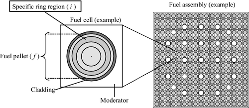
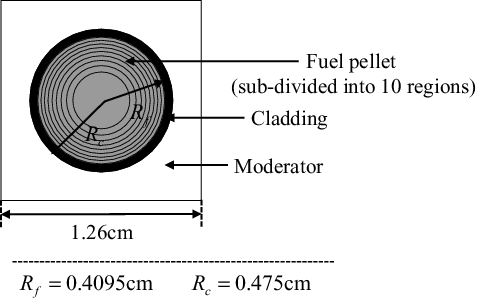
Although the hybrid resonance self-shielding method described in Section 2.2 can treat any type of fuel lump geometry in an assembly that can be handled by MOC flux calculation, the spatially dependent resonance self-shielding effect within a specific fuel lump cannot be directly treated. One of the important issues in this research field is consideration of the radially dependent resonance self-shielding effect within a cylindrical fuel rod. In this section, the neutron flux in a local ring region within a fuel rod is derived as a natural extension of EquationEquations (1)(1)
(1) –(Equation4
(4)
(4) ). Here, the radially sub-divided fuel rod discussed in this section is shown in .
The integral form of neutron transport equation for multi-region heterogeneous system consisting of multiple fuel ring regions and a non-fuel region is written as
(5)
(5)
In the following derivation, the non-fuel region is defined as the multiple regions except for fuel region. For a typical LWR unit cell, non-fuel region is composed of cladding and moderator regions.
The reciprocity theorem between regions i and j is written as
(6)
(6)
By applying EquationEquation (6)(6)
(6) to the neutron source term, the first term in the right-hand side of EquationEquation (5)
(5)
(5) is rewritten as
(7)
(7)
The second term in the right-hand side of EquationEquation (5)(5)
(5) is also rewritten as
(8)
(8) where the total cross-section for the non-fuel region is approximated as the potential scattering cross-section, i.e. Σnft(E)≅Σsnf(E)≅Σnfp.
By assuming that the macroscopic total cross-section and scattering source are spatially flat within a fuel pellet, EquationEquation (7)(7)
(7) is approximated as
(9)
(9) where Sf(E) denotes the scattering source for the fuel region, and the following relation for collision probability is used:
(10)
(10)
When the scattering source for the non-fuel region is written as , which is consistent with the hybrid resonance treatment briefly described in Section 2.2, EquationEquation (8)
(8)
(8) is approximated as
(11)
(11) where μ(E) is already defined by EquationEquation (3)
(3)
(3) in Section 2.2.
Substitution of EquationEquations (9)(9)
(9) and (Equation11
(11)
(11) ) into the right-hand side of EquationEquation (5)
(5)
(5) , and some transformations can yield
(12)
(12)
Since the scattering source for the fuel region is expressed as , which is consistent with the hybrid resonance treatment in Section 2.2, EquationEquation (12)
(12)
(12) is further modified as:
(13)
(13)
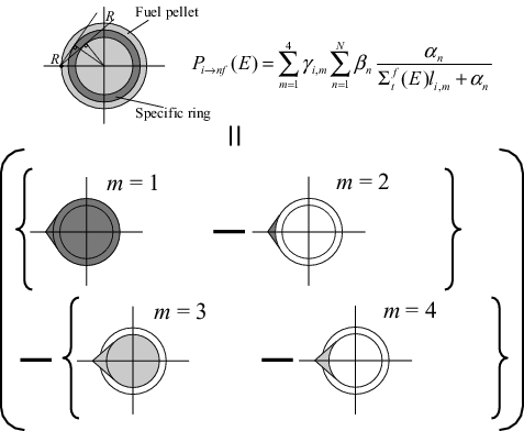
In the multi-term rational approximation of the fuel escape probability, Pi → nf(E) is formulated as [Citation4]:
(14)
(14)
EquationEquation (14)(14)
(14) is identical to the SDGM (Spatially Dependent Gray resonance self-shielding Method) formulation [Citation4], and its derivation idea is based on the Stoker–Weiss method [Citation8] and SDDM [Citation9]. A geometrical treatment of the escape probability, which is composed of four lump components (m = 1, 2, 3, 4), is shown in .
Here, γi, m in EquationEquation (14)(14)
(14) denotes the coefficient that captures the geometrical information of the ring i and is defined as
(15)
(15)
li, m denotes the mean chord length of m-th lump derived by the following analytical form:
(16)
(16)
By substituting EquationEquation (16)(16)
(16) into EquationEquation (15)
(15)
(15) , ∑4m = 1γi, m = 1. Considering that ∑Nn = 1βn = 1, the following relation is derived:
(17)
(17)
By substituting EquationEquations (14)(14)
(14) and (Equation17
(17)
(17) ) into EquationEquation (13)
(13)
(13) , the energy-dependent neutron flux for the ring region i within a fuel pellet is derived as
(18)
(18)
The scattering source Si(E) is also calculated as EquationEquation (19)(19)
(19) , which is consistent with the hybrid resonance treatment:
(19)
(19)
Here, the isotropic and elastic down-scattering approximations in the center-of-mass system are applied to each ring region within a fuel pellet. The scattering source for the non-fuel region is consistent with the hybrid resonance treatment.
By considering the spatially dependent scattering source within a fuel pellet, the neutron flux is modified from EquationEquation (18)(18)
(18) as
(20)
(20) where
(21)
(21) and η(E) denotes the energy-dependent flux normalization factor in which the fuel-pellet averaged flux obtained from EquationEquation (1)
(1)
(1) can be preserved. Σisd(E) and η(E) are the only differences between EquationEquations (20)
(20)
(20) and (Equation18
(18)
(18) ).
2.4. First-step resonance calculation based on equivalence theory and ultra-fine-group slowing-down calculation
As described in Section 2.1, the two-step resonance calculations are performed in the present method. The first-step calculation is based on the equivalence theory and the ultra-fine-group slowing-down calculation, and the space-dependent ultra-fine-group neutron fluxes for each fuel region are appropriately obtained.
As already shown in Section 2.2, the ultra-fine-group fluxes for each fuel region within an assembly are calculated from a set of slowing-down equations shown in EquationEquations (1)(1)
(1) –(Equation4
(4)
(4) ). Besides, as derived in Section 2.3, spatially dependent ultra-fine-group fluxes and scattering sources for each ring region within a fuel pellet can be obtained. It should be noted that the fluxes for each ring can be obtained analytically with small computational burdens. Σfsd(E) and μ(E) in EquationEquation (18)
(18)
(18) are the byproducts of the solution of EquationEquations (1)
(1)
(1) –(Equation4
(4)
(4) ), and thus fluxes for each ring region are easily regenerated.
In principle, the radially dependent effective cross-sections for each ring region can be generated at this single step by using the ultra-fine-group flux solution as a collapsing weight. However, as shown in a derivation scheme of the equation, the following assumptions are applied:
| (1) | The ultra-fine-group macroscopic total cross-section and scattering source are spatially flat within a fuel pellet (EquationEquation (9) | ||||
| (2) | The fuel escape probabilities for each fuel ring are expressed by the multi-term rational approximation based on the SDGM formulation (EquationEquation (14) | ||||
As shown in the verification results of Section 4, these assumptions cause the prediction error of effective cross-sections for each ring region, as a result of the prediction error of the ultra-fine-group flux.
In order to mitigate the influence of prediction error for the flux, the effective cross-sections are not generated at this step. Instead, the sub-group cross-sections are generated by using the ultra-fine-group fluxes obtained from the first-step calculation. A more accurate spatial transport of neutrons within a fuel pellet is taken into account in the second-step calculation by the additional transport calculations based on the sub-group method. The lack of accurate collision probability information for all the region-to-region combinations in a target system, which is due to the assumptions in EquationEquations (9)(9)
(9) and (Equation14
(14)
(14) ), is compensated by the second-step calculation. The details are described in the next section.
2.5. Second-step resonance calculation based on sub-group method
The second-step calculation is based on the sub-group method, and the space-dependent sub-group neutron fluxes for each region are obtained.
In the typical resonance energy ranges, the scattering source is isotropic [Citation6] and the fission source can be ignored. Therefore, the integro-differential form of neutron transport equation is written as
(22)
(22) where Ω denotes unit vector for direction, and ψi(E, Ω) denotes angular flux for region i.
By integrating EquationEquation (22)(22)
(22) against an explicit sub-group energy range sg ( ∈ g), in which the discrete energy range is permitted, the sub-group transport equation is derived as
(23)
(23) where
: macroscopic sub-group total cross-section,ψisg(Ω) ≡ ∫sgdEψi(E, Ω): sub-group angular flux,Sisg ≡ ∫sgdESi(E): sub-group scattering source.
Here, the angular dependence of energy-dependent flux within each sub-group is ignored.
The typical scheme to solve EquationEquation (23)(23)
(23) is MOC or SN (discrete ordinate) method. If MOC is adopted as a flux calculation scheme for EquationEquation (23)
(23)
(23) , the spatially dependent flux for each sub-group can be obtained for any type of complicated geometry, which can be represented by the MOC. Although the integro-differential form of neutron transport equation is shown as a typical example, the integral form of equation based on the collision probability method can also be utilized.
The microscopic sub-group cross-section for resonance nuclide r and reaction type x is also defined in the same manner as
(24)
(24)
The sub-group cross-sections are generated by the direct energy collapsing of σrx(E) with φi(E) weight obtained from the first-step calculation.
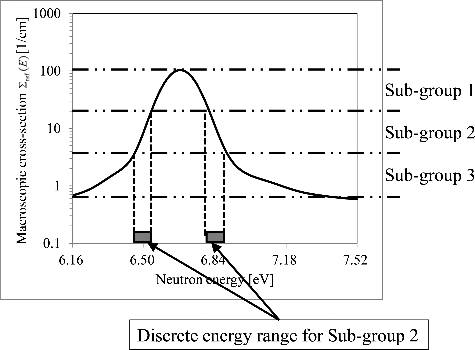
As described in Section 2.4, the sub-group transport calculation is performed in order to mitigate the influence of prediction error of φi(E) for σr, ix, sg. From this point of view, sub-group energy structure should be divided not by the neutron energy but by the resonance cross-section level. Based on a reference ultra-fine-group cross-section Σref(E), the sub-group energy structure is determined as
(25)
(25) where Σboundsg, max and Σboundsg, min denote the maximum and minimum resonance cross-section boundaries for sub-group sg ( ∈ g), respectively. Typically, Σref(E) is defined by a volume-averaged ultra-fine-group cross-section for all the fuel regions in a target system such as a fuel assembly. According to the preliminary sensitivity studies, the macroscopic absorption cross-section is a better index than the total cross-section. Though the boundaries Σboundsg, max and Σboundsg, min are determined for each sub-group sg with arbitrary interval division of resonance cross-section within a group g, the equal interval with logarithmic scale is better than that with linear scale. A concept for determination of sub-group structure is shown in .
Here, it should be noted that the defined sub-group energy structure is commonly used for all the spatial regions in sub-group cross-section generation. Even if the fuel temperature distribution within a fuel pellet is taken into account, the only one sub-group structure, e.g. a structure defined by Σref(E) for effective fuel temperature [Citation15] condition, must be applied. If the different sub-group energy structures are used for each region in sub-group cross-section generation, i.e. the different Σref(E)s are applied to each region, the neutron balance among each region and each sub-group is not preserved due to inconsistency of energy group structure for each sub-group, which is an essential issue for the conventional sub-group method.
The sub-group scattering source Sisg = ∫sgdESi(E) is also generated from Si(E) based on EquationEquation (19)(19)
(19) . From the viewpoint of computational efficiency, the sub-group scattering source calculation in the present method has an advantage compared with the conventional sub-group method. The scattering source can be calculated with fine energy resolution by EquationEquation (19)
(19)
(19) , and thus the accurate sub-group scattering source is easily obtained in advance by energy integration of Si(E). This fact enables to treat the scattering source term as a constant in EquationEquation (23)
(23)
(23) , as well as the sub-group cross-section. Therefore, EquationEquation (23)
(23)
(23) can be solved independently for each sub-group, and any considerations of sub-group to sub-group transmission probability are not required at all.
Finally, the sub-group flux φisg is obtained by integrating the angular flux solutions of EquationEquation (23)(23)
(23) . In addition to the integro-differential form of equation, φisg can also be obtained from the integral form of transport equation based on the collision probability method.
By using the sub-group cross-sections and fluxes, the microscopic effective cross-section for resonance nuclide r, reaction type x and energy group g is derived as
(26)
(26)
As described before, σr, ix, sg is generated by the ultra-fine-group flux solution φi(E) in the first-step resonance calculation (see Sections 2.2–2.4). σr, ix, sg has a fuel rod position dependence within a fuel assembly because EquationEquations (1)(1)
(1) –(Equation4
(4)
(4) ) are solved with position-dependent rational coefficients. In addition, σr, ix, sg has a radial dependence within each fuel pellet because the solution of EquationEquations (1)
(1)
(1) –(Equation4
(4)
(4) ) can be extended to the radial multi-region geometry for cylindrical fuel rod based on a derivation in Section 2.3.
On the other hand, φisg is calculated by using σr, ix, sg and Sisg. φisg is obtained with a fine spatial resolution which can be treated by the adopted flux solver. Therefore, at least, fuel rod position and intra-pellet radial dependences of effective cross-sections can be taken into account in the present method. Besides, intra-pellet azimuthal dependence of effective cross-sections can also be considered through φisg if MOC is adopted for a sub-group flux calculation.
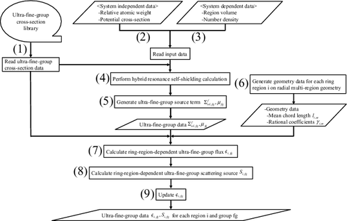
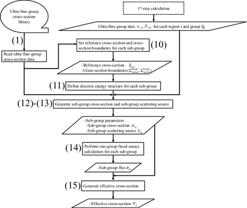
2.6. Calculation flow
A calculation flow of the two-step resonance treatment is shown in and . The calculation procedure is described below. Steps (Equation1(1)
(1) )-(9) and (Equation10
(10)
(10) )-(15) correspond to the first- and second-step resonance calculations, respectively. Note that the details for Step (Equation4
(4)
(4) ) are described in Reference [Citation7].
(1) Read the microscopic ultra-fine-group cross-section data σfg (fg: ultra-fine-group number) from the library. (Note: In the following description, continuous energy-dependent parameters are converted to ultra-fine-group form, e.g. σ(E) → σfg, for numerical treatment.)
(2) Read the relative atomic weight to the neutron, A, and the microscopic potential scattering cross-section σp.
(3) Read the heterogeneous region volume V and the number density N.
(4) Perform the hybrid resonance self-shielding calculation [Citation7] based on integration of the equivalence theory and the ultra-fine-group calculation.
(5) Generate the ultra-fine-group source terms (Σfsd, fg and μfg) for 1 ⩽ fg ⩽ FG (FG: the number of ultra-fine-group).
(6) Generate li, m and γi, m based on EquationEquations (16)
(16)
(16) and (Equation15
(15)
(15) ), respectively.
(7) Calculate the ring-region-dependent ultra-fine-group flux φi, fg for 1 ⩽ fg ⩽ FG based on EquationEquation (18)
(18)
(18) , by using Σfsd, fg and μfg.
(8) Calculate the ring-region-dependent ultra-fine-group scattering source Si, fg for 1 ⩽ fg ⩽ FG based on EquationEquation (19)
(19)
(19) , by using φi, fg and μfg.
(9) Update φi, fg based on EquationEquations (20)
(20)
(20) and (Equation21
(21)
(21) ).
(10) Set the reference cross-section Σref and the cross-section boundaries (maximum: Σboundsg, max , minimum:Σboundsg, min ) for each sub-group used in EquationEquation (25)
(25)
(25) .
(11) Define the discrete energy structure for each sub-group based on EquationEquation (25)
(25)
(25) .
(12) Generate the sub-group cross-section σr, ix, sg for 1 ⩽ sg ⩽ SG (SG: the number of sub-group) based on EquationEquation (24)
(24)
(24) , by using φi, fg.
(13) Generate the sub-group scattering source Sisg for 1 ⩽ sg ⩽ SG based on Sisg = ∫sgdESi(E), by using Si, fg.
(14) Perform the one-group fixed-source calculations for each sub-group, and obtain the fluxes φisg for each region.
(15) Generate the effective cross-section σr, ix, g based on EquationEquation (26)
(26)
(26) , by using σr, ix, sg and φisg.
2.7. Relation to the conventional methods
As described in Section 1, the present resonance treatment is a unified approach of the conventional three methods, i.e. equivalence theory, ultra-fine-group slowing-down calculation and sub-group method.
The present method is equivalent to the equivalence theory, if (i) NR approximation of the scattering source, i.e. Σfsd(E) ≈ Σpf and μ(E) ≈ 1 (see EquationEquations (2)(2)
(2) and (Equation3
(3)
(3) )), is applied to the first-step calculation, (ii) the resonance absorptions of background isotopes are ignored, and (iii) the number of sub-groups is set as one for the second-step calculation. The present method is also equivalent to the ultra-fine-group slowing-down calculation, if the sub-group is the same as the ultra-fine energy group structure for the second-step calculation. If the problem-independent sub-group parameters are prepared in advance, the present method is equivalent to the sub-group method. Therefore, the present resonance treatment is a generalized approach of the conventional three resonance self-shielding methods.
3. Reaction-rate preservation for reduction of energy discretization error
3.1. Concept for two-step reaction-rate preservation scheme
The effective cross-sections obtained from the direct energy collapsing with flux weight cannot be directly applied to the subsequent multi-group flux calculation due to the energy collapsing error. In order to reduce the error, a reaction-rate preservation scheme is necessary for heterogeneous geometry. In the conventional scheme [Citation6,Citation7] based on the SPH method [Citation16], the group-dependent correction factor fig is derived as
(27)
(27) where
denotes the flux obtained with figσx, gr, i.
The present resonance self-shielding treatment, especially for the first-step calculation, is based on the ultra-fine-group calculation, and thus the conventional scheme can be applied in principle.
Besides, the present method includes the essence of the equivalence theory. The energy-dependent neutron flux can be regenerated by the analytical form of the multi-term rational equation. Considering the fundamental concept of the reaction-rate preservation scheme in the equivalence theory [Citation17], the following equation to solve fig is formulated as a natural extension of the hybrid resonance treatment in Reference [Citation7]:
(28)
(28) where
(29)
(29)
(30)
(30)
EquationEquations (20)(20)
(20) and (Equation21
(21)
(21) ) are used in the above derivation. Here, it should be noted that EquationEquations (27)
(27)
(27) or (Equation28
(28)
(28) ) is valid only if φi(E) is obtained with high accuracy. As described in Section 2.3, some approximations are applied to the derivation process of φi(E), and thus φi(E) is not necessarily so accurate for direct application to EquationEquations (27)
(27)
(27) or (Equation28
(28)
(28) ). Therefore, a new reaction-rate preservation scheme is developed in the present study so that the influence of prediction error of φi(E) is mitigated.
The fundamental form of reaction-rate preservation equation is written as:
(31)
(31)
From the viewpoint of consistency with the present two-step resonance treatment described in Section 2, EquationEquation (31)(31)
(31) is divided into the following two equations:
(32)
(32)
(33)
(33) where
denotes the flux obtained with fisgσx, sgr, i. EquationEquation (32)
(32)
(32) is the reaction-rate preservation equation between ultra-fine-group and sub-group treatments, and EquationEquation (33)
(33)
(33) is the reaction-rate preservation equation between sub-group and multi-group treatments. EquationEquation (32)
(32)
(32) is decomposed for each sub-group as:
(34)
(34)
Note that EquationEquation (32)(32)
(32) is satisfied if EquationEquation (34)
(34)
(34) is valid.
In the present resonance treatment, the sub-group-wise correction factor fisg and the corrected flux are generated as the first-step calculation by EquationEquation (34)
(34)
(34) . Then, the multi-group-wise correction factor fig is obtained as the second-step calculation by EquationEquation (33)
(33)
(33) . If EquationEquations (28)
(28)
(28) –(Equation30
(30)
(30) ) are directly used, a significant error for fig is induced, as shown in Section 4.3.4. By utilizing the sub-group based information, direct propagation of φi(E) prediction error to fig is mitigated. This treatment is called the two-step reaction-rate preservation scheme in the present study, and its detail is described in the following sections.
3.2. First-step correction factor calculation for sub-group level
The correction factor calculation for the first step is carried out based on EquationEquation (34)(34)
(34) . By the same derivation scheme for the reaction-rate preservation in the hybrid resonance treatment, EquationEquation (34)
(34)
(34) is rewritten as
(35)
(35) where
(36)
(36)
(37)
(37)
EquationEquations (20)(20)
(20) and (Equation21
(21)
(21) ) are used in the above derivation.
EquationEquation (35)(35)
(35) is used to calculate a correction factor for reaction-rate preservation, which is consistent with the resonance treatment in Sections 2.2 and 2.3. All the terms except for fisg are byproducts of the solution of the methods described in Sections 2.2 and 2.3. fisg is easily obtained from iterative calculation until fisg is converged. From EquationEquation (35)
(35)
(35) , fisg for (s + 1)th iteration is generated by using sth result as follows:
(38)
(38)
The method includes the iteration scheme, but any additional iterative flux calculations are no longer required. The calculation time of fisg is negligible compared with the conventional scheme.
3.3. Second-step correction factor calculation for multi-group level
The correction factor calculation for the second step is carried out based on EquationEquation (33)(33)
(33) . By substituting EquationEquation (26)
(26)
(26) into EquationEquation (33)
(33)
(33) , the correction factor is derived as
(39)
(39)
In the above equation, the microscopic cross-section is included in fig, and thus it depends on resonance nuclide and reaction type. This definition of correction factor leads to the large computational burdens.
In order to avoid the nuclide and reaction type dependent correction factor calculations, the modified correction factor and the effective cross-section
are defined so as to satisfy the following relation:
(40)
(40)
By substituting EquationEquation (40)(40)
(40) into the right-hand side of EquationEquation (33)
(33)
(33) , the following equation is obtained:
(41)
(41)
Here, is defined as an effective cross-section in which the energy discretization error associated with the collapsing only from the ultra-fine-group to the sub-group is removed, i.e.,
(42)
(42)
By substituting EquationEquation (42)(42)
(42) into EquationEquation (41)
(41)
(41) , the modified multi-group correction factor
is derived as
(43)
(43)
As shown in EquationEquation (43)(43)
(43) ,
does not depend on resonance nuclide and reaction type like an SPH factor. In other words,
is defined in EquationEquation (42)
(42)
(42) so that the resonance nuclide and reaction type dependence of the correction factor can be removed.
Finally, the corrected effective cross-section, which is provided for the subsequent multi-group flux and depletion calculations in a lattice physics code, is . It should be noted that the effective cross-section, which is comparable to the continuous energy Monte-Carlo results tallied by a simple flux weight scheme, is σr, ix, g.
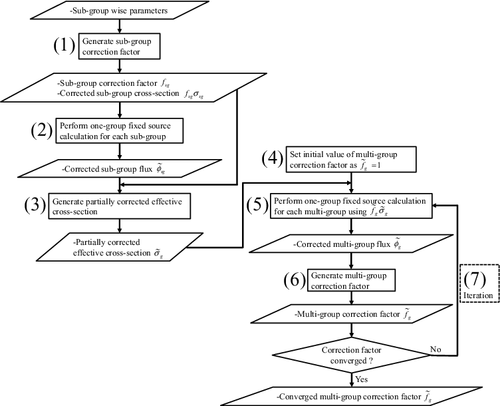
3.4. Calculation flow
Calculation flow of the two-step reaction-rate preservation scheme established in Sections 3.1–3.3 is shown in . The calculation procedure is described as follows:
(1) Generate the sub-group-wise correction factor fisg based on EquationEquation (35)
(35)
(35) with iteration scheme of EquationEquation (38)
(38)
(38) .
(2) Perform one-group fixed-source calculations for each sub-group by using the corrected sub-group cross-section fisgσx, sgr, i as an input, and obtain the sub-group flux
. This calculation can be carried out independently.
(3) Generate the partially corrected effective cross-section
, in which the energy discretization error from the ultra-fine-group to the sub-group collapsing is removed, based on EquationEquation (42)
(42)
(42) .
(4) Set the initial value of
as
.
(5) Perform one-group fixed-source calculation for each multi-group by using the corrected effective cross-section
as an input, and obtain the multi-group flux
. This calculation can be carried out independently.
(6) Generate the multi-group-wise modified correction factor
based on EquationEquation (43)
(43)
(43) .
(7) Iterate (Equation5
(5)
(5) ) and (6) until
is converged.
Steps (Equation1(1)
(1) )–(3) and (Equation4
(4)
(4) )–(7) correspond to the first- and second-step correction factor calculations, respectively.
4. Verification
4.1. Concept
In this section, the present resonance treatment is verified by the numerical calculations. The present method is composed of multiple components based on a unified theory, and thus each component is verified first (Section 4.3). Then, the effective cross-sections, i.e. final products of the resonance calculation, are analyzed for various cases as a total verification (Section 4.4). The reference solutions are obtained from the continuous energy Monte-Carlo calculations based on the exact geometry modeling and fine cross-section representation with continuous energy resolution. A part of the references is obtained from the heterogeneous ultra-fine-group slowing-down calculation based on a deterministic method.
The analysis condition is shown in Section 4.2. The verification results for fundamental parameters of the present method are shown in Section 4.3. The application results for various pin-cell and multi-cell problems are shown in Section 4.4. The verification list is shown in .
Table 3. Verification list
4.2. Analysis condition
Analysis condition of the new resonance treatment is described in this section.
In order to perform each process in the calculation scheme of the present method (see Sections 2.6 and 3.4), a standalone program is developed. The MHI (Mitsubishi Heavy Industries, Ltd.) lattice physics code GALAXY (Geometrically Arbitrary, Lattice physics and Assembly calculation code in X-Y coordinate system) [Citation4,Citation7,Citation18,Citation21] is used for several steps in the process. In concrete, ‘(1)–(5) and (Equation14(14)
(14) )’ in and and ‘(2) and (Equation5
(5)
(5) )’ in are performed by GALAXY. The GALAXY ultra-fine-group cross-section library (120,000 groups) [Citation7] based on ENDF/B-VII.0 [Citation19] is also utilized.
The number of rational equation terms used for one-region fuel is set to N = 2. Note that the total number of terms used for multi-region fuel is 4N = 8 (see EquationEquation (18)(18)
(18) ). The microscopic effective capture cross-sections of 238U are generated for 88th energy group (6.16–7.52 eV) of the XMAS 172 energy group structure [Citation20], in which the wide resonance cross-section of 238U is included. The number of sub-groups is 5, and the sub-group energy structure is determined by EquationEquation (25)
(25)
(25) based on the ultra-fine-group macroscopic absorption cross-section of the fuel region as Σref(E). The sub-group boundary for the absorption cross-section is determined by a division with equal interval in logarithmic scale. The sub-group transport calculation is performed by the collision probability method based on the equivalent Dancoff method [Citation21]. These conditions are applied to almost all the analyses in this paper. The sensitivities for the above calculation conditions against effective cross-sections are investigated in advance, and it is confirmed that the calculation conditions are sufficient from the view point of prediction accuracy for effective cross-sections.
UO2 (4.8wt% 235U) pin-cells with HFP (hot full power) operating conditions are set as the typical LWR neutron spectrum condition. The specifications of the pin-cell problem are shown in , and the geometrical configuration is shown in . The pellet region is sub-divided into 10 equal volume rings for radial direction. The fuel composition and temperature are assumed to be flat within a pellet. Calculation for the one-region pellet model is also performed for comparisons.
Table 4. Specifications of the pin-cell model
In Sections 4.3.1, 4.3.3, and 4.3.5, the calculation results by the present method are compared with those by the continuous energy Monte-Carlo code MVP (Monte Carlo code for vector processors) [Citation22]. The ENDF/B-VII.0 nuclear data library is used in all the MVP calculations to be consistent with the calculations by the present method. The total number of neutron sampling for MVP calculations is set to 100 million histories, in which the 1σ statistical error of the effective cross-sections is about 0.1%.
For the scattering kernel treatment, all the analyses including the reference calculations by the continuous energy Monte-Carlo are performed with the conventional asymptotic scattering model, as shown in EquationEquation (2)(2)
(2) . In this paper, discussion for the selection of scattering model, i.e. the asymptotic model or the exact resonance scattering model [Citation23,Citation24], is out of scope. The present resonance treatment is verified with reference calculations based on the same scattering model.
In Sections 4.3.2 and 4.3.4, the calculation results by the present method are compared with those by the direct ultra-fine-group slowing-down calculation with heterogeneous geometry. The heterogeneous slowing-down calculation is performed by the equivalent Dancoff method [Citation21] implemented in GALAXY, which is a different resonance treatment from the hybrid resonance treatment [Citation7] and the present method.
The equivalent Dancoff method is applied to a part of the reference calculations, in which the continuous energy Monte-Carlo calculations cannot be used to obtain reference results since specific conditions dedicated for the deterministic method are used and cannot be reproduced by the Monte-Carlo method. The reliability of the equivalent Dancoff method itself is also shown in Section 4.3.3 through comparisons of effective cross-sections against the MVP results.
4.3. Verification for fundamental parameters of the present method
4.3.1. Ultra-fine-group neutron flux
The ultra-fine-group neutron flux by the first-step calculation of the present method is compared with the continuous energy Monte-Carlo result in this section.
As described in Section 2.2, a set of the slowing-down equations (EquationEquations (1)(1)
(1) –(Equation4
(4)
(4) )) are solved for one-region pellet system, based on the hybrid resonance treatment [Citation7] of the equivalence theory and the ultra-fine-group slowing-down calculation. Σfsd(E) and μ(E) are numerically obtained as byproducts of the solution for EquationEquations (1)
(1)
(1) –(Equation4
(4)
(4) ). Then by EquationEquations (20)
(20)
(20) and (Equation21
(21)
(21) ), which are derived in Section 2.3, the ultra-fine-group flux for each sub-region of a pellet is analytically obtained.
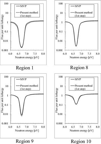
The ultra-fine-group fluxes for each sub-region of a pellet by the present method and those by the continuous energy Monte-Carlo calculation (MVP) are shown in including 88th energy group (6.16–7.52 eV) of XMAS 172 energy group structure. The results for Regions 1, 8, 9, and 10 (sequentially numbered from the center to the surface of a pellet) are plotted for convenience. As shown in , the present method (first-step calculation) can roughly predict the ultra-fine-group neutron flux comparable to the continuous energy Monte-Carlo results. However, a slight difference is observed. The flux differences are induced by the approximation of spatially dependent fuel escape probability and scattering source within a pellet, which are applied to the flux derivation scheme in Section 2.3. As shown in Section 4.3.3, the differences of the ultra-fine-group flux directly cause the differences of effective cross-section between the present method ‘without second-step calculation’ and the MVP. The differences of effective cross-section owing to ultra-fine-group flux estimation are mitigated by the second-step calculation based on the sub-group flux, as shown in Section 4.3.3.
Figure 9. Comparison of ultra-fine-group fluxes between the present method (first-step calculation) and the continuous energy Monte-Carlo calculation (MVP).
A breakdown of the calculation time for ultra-fine-group flux calculation in all the ring regions within a pellet is shown in . As shown in , the calculation time is very short, and thus the time is negligible against the total computation time of the lattice physics calculations. On the basis of its short computation time, the present method can be easily applied to the large and heterogeneous geometry such as a fuel assembly. In the present method, at first, the fuel-rod-wise ultra-fine-group flux is independently obtained for each fuel cell by EquationEquations (1)(1)
(1) –(Equation4
(4)
(4) ) and the cell-dependent coefficients αn, βn, ϵn and θ. Then, the obtained ultra-fine-group data in each fuel rod is expanded for each ring region by using the ring-dependent coefficients γm. Utilization of a set of coefficients for the rational equation improves the computational efficiency of the ultra-fine-group calculation, compared with the direct heterogeneous ultra-fine-group transport calculation.
Table 5. Calculation time for the ultra-fine-group flux
4.3.2. Sub-group cross-section
The sub-group cross-sections in fuel regions are generated by the present method. The results are compared with the reference solutions obtained from the direct heterogeneous ultra-fine-group calculation by the equivalent Dancoff method.
The sub-group cross-sections and the corresponding differences from the direct heterogeneous ultra-fine-group calculation results are shown in . The differences of the effective cross-section between the present method ‘without second-step calculation’ and the reference solution are also shown in the figure. As shown in , the present method can accurately predict the sub-group cross-sections, while the effective cross-section generated by the present method ‘without second-step calculation’ includes some differences.
Figure 10. Sub-group cross-sections and their differences from the direct heterogeneous ultra-fine-group calculation results.
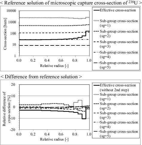
The influence of ultra-fine-group flux error (see Section 4.3.1) on sub-group cross-section is mitigated by defining the sub-group energy structure, not for energy but for macroscopic absorption cross-section level.
4.3.3. Effective cross-section
The effective cross-sections in fuel regions are generated by the present method. The results are compared with the reference solutions obtained from the continuous energy Monte-Carlo code MVP. The results based on the equivalence theory (SDGM [Citation4] with the NR approximation), the direct heterogeneous ultra-fine-group calculation (the equivalent Dancoff method [Citation21]) and the present method ‘without second-step calculation’ are also obtained for comparison.
The effective cross-sections and the corresponding differences from the MVP results are shown in . As shown in , the present method (first + second-step calculation) can accurately predict the effective cross-sections.
Figure 11. Effective cross-sections and their differences from the continuous energy Monte-Carlo calculation (MVP).
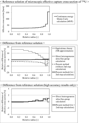
In contrast, the results obtained by the equivalence theory with NR approximation and by the present method ‘without second-step calculation’ show the large difference from the reference solutions. For the latter method, the difference is due to the prediction error of ultra-fine-group fluxes in the case of treating radially sub-divided fuel region (see Section 4.3.1).
From the result, the effectiveness of incorporating the sub-group method as the second-step calculation is confirmed. The influence of ultra-fine-group flux error on the final effective cross-section is efficiently reduced by the two-step flux calculation scheme of the present method, i.e. the flux calculation for ‘coarse geometry + fine energy’ (first step) and that for ‘fine geometry + coarse energy’ (second step). The prediction accuracy of effective cross-section is appropriately improved by reflecting the more detailed information of spatial neutron transport within a pellet based on the second-step sub-group calculation.
The differences of the effective cross-sections from those of the MVP results are summarized in . The results obtained by one-region pellet model are also shown in the table. From , the present two-step method provides an excellent result for multi-region case, which is almost comparable to the direct heterogeneous ultra-fine-group calculation.
Table 6. Differences of effective cross-section from the continuous energy Monte-Carlo calculation (MVP)
The calculation efficiency is also an important viewpoint for the total performance of a target method. The required number of one-group fixed-source transport calculations is estimated in . In the conventional equivalence theory based on the Dancoff method, the one-group calculation is required only one time in the black neutron absorber condition. If the equivalence theory based on the gray resonance treatment [Citation4] is adopted, the one-group calculation is required several times for a wide range of macroscopic total cross-section conditions. After all, the conventional equivalence theory requires only 1-20 times of one-group transport calculations. In contrast to the equivalence theory, the direct heterogeneous ultra-fine-group method generally requires 10,000–200,000 times of one-group transport calculations, which is large computational burden.
Table 7. Estimation for the number of one-group fixed-source transport calculations
The present method has an intermediate feature between the above two methods. If the number of multi-groups, in which the resonance self-shielding treatment is required, is 100, and the number of sub-groups is set to 5 for each group, the required number of one-group transport calculations is 100×5 = 500. As a result, the required number of one-group transport calculations in the present method is less than 1/10 of that in the direct heterogeneous ultra-fine-group method, as shown in .
The calculation time for a fuel assembly geometry is an important point for practical lattice physics calculations. The calculation time for a fuel assembly is estimated in . In the estimation, the steady-state calculations for a typical PWR type 17×17 4.8wt% UO2 assembly are carried out by the lattice physics code GALAXY.
Table 8. Brief estimation for the calculation time on fuel assembly geometry
As for the treatment of fuel pellet, the two cases (‘no-division’ and ‘sub-division for radial direction with 10 equal volume rings’) are analyzed. For each case, the resonance treatment methods based on the equivalence theory [Citation4] and the direct ultra-fine-group calculation [Citation21] are applied for comparison with the present method, and their calculation times are directly measured. Since the present method is not implemented into the GALAXY code at the current development state, the result for the present method is inferred by the results for the other methods and the quantitative information in and . The multi-group flux calculation is performed by ‘172 group CCCP (current-coupling collision probability) method + 22 group MOC’ [Citation21] for all cases.
As shown in , the estimated calculation times by the present method are less than one-third of those by the direct ultra-fine-group calculation for resonance calculation part. The ratios of resonance calculation part against the ‘resonance + flux’ calculations are less than 1/2 in the present method. From the results, the present method can efficiently generate effective cross-sections for large and complicated geometry such as a fuel assembly, comparing with the direct ultra-fine-group calculation.
Finally, the total performance is benchmarked for major resonance treatments, taking into account of the quantitative information in –. The result of qualitative comparison is summarized in . As shown in , the present method is better than all the three conventional methods, from the viewpoint of both calculation accuracy and time.
Table 9. Qualitative comparison of overall performance for resonance self-shielding treatments
4.3.4. Cross-section correction factor
The correction factors for effective cross-section in fuel regions to reduce energy discretization error are generated by the present method. The results are compared with the reference solutions obtained from the direct heterogeneous ultra-fine-group calculation by the equivalent Dancoff method (see EquationEquation (27)(27)
(27) in Section 3.1). The results based on the present method ‘without second-step sub-group calculation’ (see EquationEquation (28)
(28)
(28) in Section 3.1) are also obtained for comparison.
In the two-step reaction-rate preservation scheme, the relative convergence criterion of the correction factors is set as 0.1%. Only 10 iterations are necessary for the second-step calculation in this verification with this convergence criterion.
The correction factors and the corresponding differences from the direct heterogeneous ultra-fine-group calculation results are shown in . As shown in , the present method (first + second-step calculation) can accurately predict the correction factor.
Figure 12. Correction factors and their differences from the direct heterogeneous ultra-fine-group calculation results.
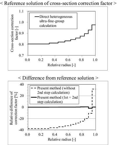
In contrast, the results obtained by the present method ‘without second-step calculation’ show the large difference from the reference solutions. The prediction error of ultra-fine-group fluxes in the case of treating radially sub-divided fuel region is the cause of the difference (see Section 4.3.1).
From the result, the effectiveness of incorporating the sub-group method as the second-step calculation is confirmed. The influence of ultra-fine-group flux error on the final correction factor is efficiently reduced by the two-step reaction-rate preservation scheme, i.e. the ultra-fine-group to the sub-group collapsing, and the sub-group to the multi-group collapsing.
4.3.5. Reaction-rate
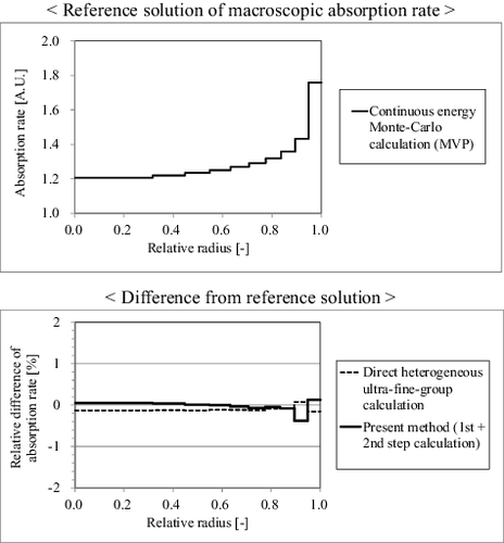
One of the final products of lattice physics calculation is reaction-rate. In order to confirm the influence of effective cross-section differences on reaction-rate, the energy-integrated macroscopic absorption rates in fuel regions are generated from the multi-group transport calculation by the lattice physics code GALAXY. The radially dependent microscopic effective cross-section set, which is generated from a standalone program based on the present method, is directly supplied to the GALAXY.
The results are compared with the reference solutions obtained from the continuous energy Monte-Carlo code MVP. The results based on the direct heterogeneous ultra-fine-group calculation by GALAXY are also obtained for comparison. In the reaction-rate calculation for each method, the neutron fluxes are normalized so that the volume and energy integrated neutron generation rate is unity.
The absorption rates and the corresponding differences from the MVP results are shown in . In this analysis, the 1σ statistical error of absorption rates by MVP is about 0.02%. The maximum relative differences from the MVP results are −0.4% for the present method, and −0.2% for the direct ultra-fine-group calculation, respectively. The difference is less than ±0.1% for most ring regions in both methods, thus the present method can accurately predict the reaction-rates, which is comparable to the direct ultra-fine-group calculation.
4.4. Application for various pin-cell and multi-cell problems
4.4.1. Radially dependent effective cross-sections with non-uniform isotope composition for unit pin-cell
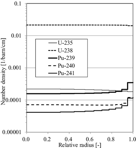
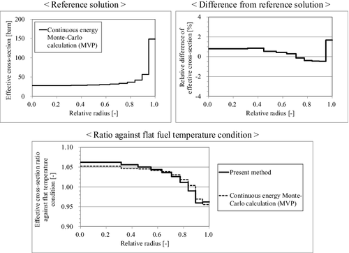
In this section, the pin-cell with non-uniform isotope composition is treated, in which the fuel composition is radially distributed. As a typical application for the LWR lattice calculations, the depleted fuel and the annular fuel are taken into account. For both fuels, the calculation conditions except for the number densities in fuel regions are the same as those given in Section 4.2.
For the depleted fuel case, the GALAXY depletion calculation is performed in advance, and the number densities for each nuclide and each ring region within a pellet are obtained. In this verification, the number densities only for main actinide nuclides, i.e. 235U, 238U, 239Pu, 240Pu, and 241Pu, are extracted for simplicity on the burnup condition of 60GWd/t, as shown in . The typical Pu build-up effect on a peripheral region of the pellet can be observed from the figure.
In this verification, the microscopic effective capture cross-sections of 238U are generated with the given region-dependent number densities. The effective cross-sections generated by the present method are compared with the reference solutions obtained from the continuous energy Monte-Carlo code MVP. The results are shown in . As shown in the figure, the present method can accurately predict the effective cross-sections with radially distributed isotope composition. The spatially dependent biases against fresh fuel condition also agree well with the Monte-Carlo results, and therefore the consistency between uniform and non-uniform fuel composition treatments is confirmed for the present method.
Figure 15. Effective cross-sections and their differences from the continuous energy Monte-Carlo calculation (MVP) with non-uniform isotope composition.
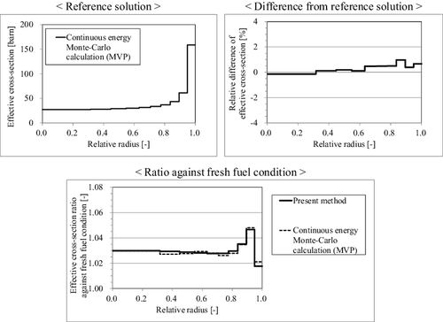
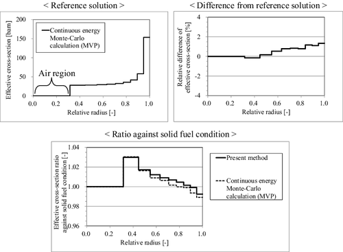
For the annular fuel case, material for the inner-most region of the pellet, which is sub-divided into 10 equal volume rings for radial direction, is assumed as air. Similar with the above depleted fuel case, the comparison of the effective cross-sections is shown in . As shown in the figure, the present method can accurately predict the effective cross-sections of annular fuel. The consistency between solid and annular fuel treatments is confirmed for the present method.
4.4.2. Radially dependent effective cross-sections with non-uniform temperature for unit pin-cell
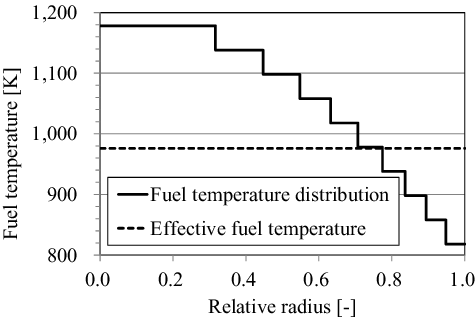
In this section, the pin-cell with non-uniform temperature is treated, in which the fuel temperature is radially distributed. The calculation conditions except for the fuel temperatures are the same as those given in Section 4.2.
The fuel temperature distribution used for the verification is shown in . The corresponding effective fuel temperature which is averaged with a chord weight [Citation15] is the same as that in .
In this verification, the microscopic effective capture cross-sections of 238U are generated with the given region-dependent temperatures. The effective cross-sections generated by the present method are compared with the reference solutions obtained from the continuous energy Monte-Carlo code MVP. The results are shown in . As shown in the figure, the spatially dependent biases against flat temperature condition agree well with the Monte-Carlo results, and therefore the consistency between uniform and non-uniform fuel temperature treatments is confirmed for the present method.
4.4.3. Radially and azimuthally dependent effective cross-sections for unit pin-cell
In this section, the radially and azimuthally divided pin-cell is treated. The calculation conditions except for the sub-division of fuel region in azimuthal direction are the same as those given in Section 4.2. The fuel pellet is sub-divided into 32 sector regions for 2π with equal azimuthal angle interval.
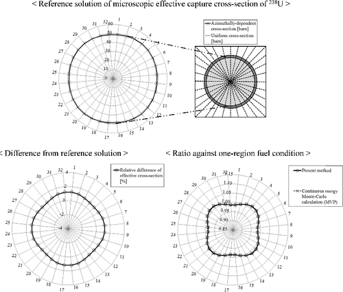
In this verification, the azimuthally dependent microscopic effective capture cross-sections of 238U are generated. The sub-group cross-sections are generated as the azimuthally independent values in the first step of the present method. The azimuthal dependence against the final effective cross-sections is taken into account by the second-step sub-group flux calculation with direct two-dimensional geometry modeling based on MOC.
The effective cross-sections generated by the present method are compared with the reference solutions obtained from the continuous energy Monte-Carlo code MVP. The total number of neutron sampling for MVP calculations is set to 500 million histories, in which the 1σ statistical error of the effective cross-sections is about 0.1-0.2%.
The results are shown in . As shown in the figure, the present method can accurately predict the azimuthally dependent effective cross-sections, in which the cross-sections tend to be larger for the diagonal directions than that for the horizontal and vertical directions due to the difference of adjacent moderator region volume. The spatially dependent biases against one-region fuel condition also agree well with the Monte-Carlo results, and therefore the consistency between one-region and azimuthal multi-region treatments is confirmed for the present method.
Figure 19. Azimuthally dependent effective cross-sections and their differences from the continuous energy Monte-Carlo calculation (MVP) for unit pin-cell.
Both the radially and azimuthally dependent effective cross-sections are also compared with the reference solutions from MVP. The results for azimuthally -dependent effective cross-section ratios for each ring region are shown in . The results for radially divided regions 1, 7, 8, 9, and 10 (sequentially numbered from the center to the surface of a pellet) are plotted for convenience. As shown in the figure, the present method can accurately predict both the radial and azimuthal dependences of effective cross-sections.
Figure 20. Azimuthally dependent effective cross-section ratios in each ring region for unit pin-cell.
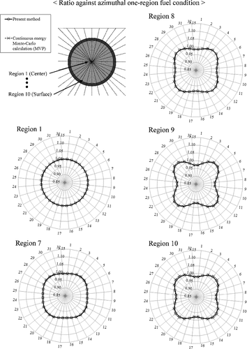
As can be observed from , the azimuthal dependence of effective cross-sections tends to be larger for the pellet surface (region 10) than that for the pellet center (region 1) due to the difference of distance from moderator region. The heterogeneous effect, which is a main contributor for yielding azimuthal dependence, is small for the pellet center. Thus the effective cross-sections are azimuthally flat for pellet center region.
Though the difference of effective cross-sections between the present method and MVP is not shown in , the difference is confirmed to be less than ±2% for all the 320 regions, which is a consistent result with in Section 4.3. Therefore, the present method can accurately predict spatially dependent effective cross-sections for both radially and azimuthally sub-divided fuel condition.
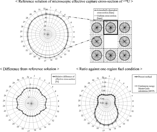
4.4.4. Azimuthally dependent effective cross-sections for 3×3 multi-cell including large water region
Finally, the 3×3 multi-cell divided in azimuthal direction is treated. A large water cell is set in the center region, simply simulating a guide thimble or an instrumentation tube in a typical PWR (Pressurized Water Reactor) fuel assembly. The calculation conditions of fuel regions except for the sub-division of fuel region in azimuthal direction are the same as those given in Section 4.2. The fuel pellet is sub-divided into 32 sector regions for 2π with equal azimuthal angle interval.
The effective cross-sections generated by the present method are compared with the reference solutions obtained from the continuous energy Monte-Carlo code MVP. The total number of neutron sampling for MVP calculations is set to 1 billion histories, in which the 1σ statistical error of the effective cross-sections is about 0.3%.
The results are shown in and . As shown in the figures, the present method can accurately predict the azimuthally dependent effective cross-sections. The spatially -dependent biases against one-region fuel also agree well with the Monte-Carlo results, and therefore the consistency between one-region fuel and azimuthal multi-region treatments is confirmed for the present method.
Figure 21. Azimuthally dependent effective cross-sections and their differences from the continuous energy Monte-Carlo calculation (MVP) for 3×3 multi-cell with large water region (corner fuel).
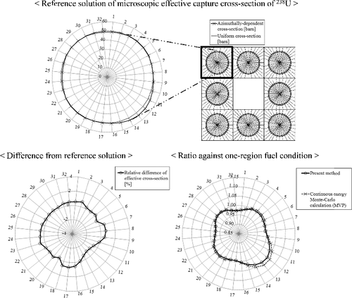
Figure 22. Azimuthally dependent effective cross-sections and their differences from the continuous energy Monte-Carlo calculation (MVP) for 3×3 multi-cell with large water region (vertical fuel).
In the conventional methods, only the direct heterogeneous ultra-fine-group slowing-down calculation and the sub-group method with two-dimensional exact geometry can generate the azimuthally dependent effective cross-sections. Therefore, the present method is an efficient alternative to treat azimuthally dependent resonance self-shielding effect, while keeping sufficient accuracy.
5. Conclusion
The unified resonance self-shielding method is developed for general application of lattice physics calculations. The present method can accurately treat the radially and azimuthally dependent resonance self-shielding effect without the direct heterogeneous ultra-fine-group calculation.
A calculation scheme of the present method is based on the concept of multi-stage cross-section collapsing strategies, and is composed of two-step calculation, i.e. ‘coarse geometry + fine energy’ (first step) and ‘fine geometry + coarse energy’ (second step) calculations. The first-step calculation corresponds to the hybrid model of the equivalence theory and the ultra-fine-group calculation, and the second step corresponds to the sub-group method. The two-step reaction-rate preservation scheme is also established to reduce energy discretization error.
From the various verification results, radially and azimuthally dependent effective cross-sections generated by the new method show good agreement with the continuous energy Monte-Carlo results for pin-cell and multi-cell geometries including non-uniform fuel compositions and temperature distributions within a pellet.
The present method can accurately generate effective cross-sections with short computation time in lattice physics calculations, and has a potential for the general application toward the next generation core analysis codes that require high fidelity and sophisticated modeling of reactors.
| Nomenclatures | ||
| Ak | = | relative atomic weight of nuclide k to the neutron |
| αk | = | maximum energy loss ratio for nuclide k defined as |
| αn | = | nth rational coefficient considering the heterogeneous and lattice effects |
| βn | = | weight of nth rational equation normalized as |
| E | = | neutron energy |
| ϵn | = | nth rational coefficient for mitigation of self-shielding effect in non-fuel region |
| f | = | fuel region |
| g | = | index for energy group (multi-group resolution) |
| k | = | index for nuclide |
| lf | = | mean chord length of fuel lump |
| li | = | mean chord length of ring region i defined as |
| μ | = | self-shielding correction factor for non-fuel region |
| N | = | the number of rational equation terms |
| n | = | index for rational equation term |
| nf | = | non-fuel region |
| Nfk | = | number density of nuclide k in fuel region |
| Nnfk | = | number density of nuclide k in non-fuel region |
| φf | = | neutron flux in fuel region |
| φi | = | neutron flux in ring region i |
| ϕnf | = | non-asymptotic component of non-fuel flux |
| Pj → i | = | collision probability from regions j to i |
| r | = | index for resonance nuclide |
| ρi | = | relative outer radius of ring i (normalized by pellet radius R) |
| ρi − 1 | = | relative inner radius of ring i (normalized by pellet radius R) |
| sg | = | index for energy group (sub-group resolution) |
| Si | = | neutron source for region i |
| Σnfp | = | macroscopic potential scattering cross-section in non-fuel region |
| Σfsd | = | slowing-down cross-section in fuel region |
| Σft | = | macroscopic total cross-section in fuel region |
| Σit | = | macroscopic total cross-section in ring region i ∈ f |
| σks | = | microscopic elastic scattering cross-section for nuclide k |
| σrx | = | microscopic cross-section for resonance nuclide r and reaction type x |
| θ | = | ratio of asymptotic spectrum in non-fuel region (0 ⩽ θ ⩽ 1) |
| ufg | = | index for energy group (ultra-fine-group resolution) |
| Vi | = | volume for region i |
| x | = | index for reaction type |
Disclosure statement
No potential conflict of interest was reported by the authors.
References
- Stamm'ler RJJ, Abbate MJ. Methods of steady-state reactor physics in nuclear design. London: Academic Press; 1983.
- Yamamoto A. Evaluation of background cross section for heterogeneous and complicated geometry by the enhanced neutron current method. J Nucl Sci Technol. 2008;45:1287–1292.
- Hébert A, Marleau G. Generalization of the Stamm'ler method for the self-shielding of resonant isotopes in arbitrary geometries. Nucl Sci Eng. 1991;108:230–239.
- Koike H, Yamaji K, Kirimura K, et al. Advanced resonance self-shielding method for gray resonance treatment in lattice physics code GALAXY. J Nucl Sci Technol. 2012;49:725–747.
- Kier PH, Robba AA. RABBLE, a program for computation of resonance absorption in multiregion reactor cells. 1967. ( ANL-7326).
- Sugimura N, Yamamoto A. Resonance treatment based on ultra-fine-group spectrum calculation in the AEGIS code. J Nucl Sci Technol. 2007;44:958–966.
- Koike H, Yamaji K, Kirimura K, et al. Integration of equivalence theory and ultra-fine-group slowing-down calculation for resonance self-shielding treatment in lattice physics code GALAXY. J Nucl Sci Technol. 2016;53:842–869.
- Stoker CC, Weiss ZJ. Spatially dependent resonance cross sections in a fuel rod. Ann Nucl Energy. 1996;23:765–778.
- Matsumoto H, Ouisloumen M, Takeda T. Development of spatially dependent resonance shielding method. J Nucl Sci Technol. 2005;42:688–694.
- Nikolaev MN, Ignatov AA, Isaev NV, et al. The method of subgroups for considering the resonance structure of the cross sections in neutron calculations. Sov At Energy. 1970;29:689–695.
- Ribon P, Maillard JM. Probability tables and gauss quadrature; Application to neutron cross-sections in the unresolved energy range. Topical meeting on advances in reactor physics and safety; Saratoga Springs; 1986.
- Askew R. A characteristics formulation of the neutron transport equation in complicated geometries. Winfrith: Atomic Energy Authority; 1972. ( AEEW-M1108).
- Yamamoto A, Koike H, Yamane Y. A new framework of resonance calculation method based on the sub-group method (1); Theory. Trans Am Nucl Soc. 2009;100:647–649. [CD-ROM].
- Cacuci DG. Handbook of nuclear engineering. Berlin: Springer; 2010.
- De Kruijf WJM, Janssen AJ. The effective temperature to be used for calculating resonance absorption in a 238UO2 lump with a nonuniform temperature profile. Nucl Sci Eng. 1996;123:121–135.
- Kavenoky A. The SPH homogenization method. Proc.Meeting Homogenization Methods in Reactor Physics; 1978 Nov 13–15; Lugano: IAEA-TECDOC-231, International Atomic Energy Agency; 1978.
- Yamamoto A, Endo T, Koike H. Improved derivation of multigroup effective cross section for heterogeneous system by equivalence theory. Nucl Sci Eng. 2011;168:75–92.
- Yamaji K, Matsumoto H, Kirimura K, et al. Development of a new lattice physics code GALAXY for flexible geometry representation in next generation core analysis system. Trans Am Nucl Soc. 2007;97:573–574. [CD-ROM].
- Chadwick MB, Oblozinsky P, Herman M, et al. ENDF/B-VII.0: next generation evaluated nuclear data library for nuclear science and technology. Nucl Data Sheets. 2006;107:2931–3060.
- Sartori E. Standard energy group structures of cross section libraries for reactor shielding, reactor cell and fusion neutronics applications: VITAMIN-J, ECCO-33, ECCO-2000 and XMAS, JEF/DOC-315, Revision 3. Gif-sur-Yvette: NEA Data Bank; 1990.
- Yamaji K, Koike H, Kamiyama Y, et al. Validation of lattice physics code GALAXY with new resonance and fast transport method. Proc. of ICAPP 2015; Nice, France; 2015.
- Nagaya Y, Okumura K, Mori T, et al. MVP/GMVP II: general purpose Monte Carlo codes for neutron and photon transport calculations based on continuous energy and multigroup methods. Ibaraki: Japanese Atomic Energy Research Institute (JAERI); 2005. ( JAERI 1348).
- Ouisloumen M, Sanchez R. A model for neutron scattering off heavy isotopes that accounts for thermal agitation effects. Nucl Sci Eng. 1990;107:189–200.
- Lee D, Smith K, Rhodes J. The Impact of 238U resonance elastic scattering approximations on thermal reactor Doppler reactivity. Ann Nucl Energ. 2009;36(3):274–280.

