 ?Mathematical formulae have been encoded as MathML and are displayed in this HTML version using MathJax in order to improve their display. Uncheck the box to turn MathJax off. This feature requires Javascript. Click on a formula to zoom.
ABSTRACT
The pseudo-resonant-nuclide subgroup method (PRNSM) based global–local self-shielding calculation scheme is proposed to simultaneously resolve the local self-shielding effects (including spatial self-shielding effect and the resonance interference effect) for large-scale problems in reactor physics calculations. This method splits self-shielding calculation into global calculations and local calculations. The global calculations obtain the Dancoff correction factor for each pin cell by neutron current method. Then an equivalent one-dimensional (1D) cylindrical problem for each pin cell is isolated from the lattice system by preserving Dancoff correction factor. The local calculation is to perform self-shielding calculations of the equivalent 1D cylindrical problem by the PRNSM. The numerical results show that PRNSM obtains accurate spatial dependent self-shielded cross sections and improves the accuracy of dealing with the resonance interference over the conventional Bondarenko iteration method and the resonance interference factor method. Furthermore, because both global and local calculation is linearly proportional to the size of problems, the global–local calculation scheme could be applied to large-scale problems.
1. Introduction
The availability of better computers allows us to build fine neutronics model of the whole nuclear reactor and observe detailed behavior of it. Coding systems based on deterministic methods such as Deterministic Core Analysis based on Ray Tracing (DeCART) [Citation1], nTRACER [Citation2], and MPACT (Michigan Prallel Analysis based on Characteristic Tracing) [Citation3] are developed to fulfill this aim. For its high precision and geometrical adaptability, the subgroup method [Citation4] is selected as an option for the whole-core self-shielding calculation in these coding systems.
Several studies have been made to make the subgroup method practical for large-scale self-shielding calculations, including the stable fitting procedure of the probability table [Citation6], the one dimensional (1D) heterogeneous pin cell configurations and compositions instead of the zero-dimensional (0D) configurations and compositions are used to generate cross sections (XSs) at different dilutions [Citation5]. More recently, the resonance interference factor method (RIFM) is developed to consider the resonance interference effect [Citation6]. The subgroup method is derived based on one-resonant-nuclide assumption which is not consistent with the real problem containing multiple resonant nuclides. To cope with the resonance interference effect, the Bondarenko iteration method (BIM) has long been used. However, this method is shown to introduce large errors in dealing with the resonance interference effect. Therefore, the RIFM is proposed and widely used to correct the self-shielded cross sections (XS) for considering resonance interference. Another class of method to treat resonance interference effect is the conditional probability method developed by Takeda and Kanayama [Citation7] and the correlated weight matrix method proposed by Hébert [Citation8]. But these methods suffer from the computation time and still have improvement gap over BIM. Therefore, they will not be discussed in this paper.
Despite these improvements, there still exist several problems when directly applying the subgroup method to large-scale self-shielding calculations. First, fixed-source calculation over the whole spatial domain is needed for each subgroup, which is time-consuming. Second, though the effort of converting from the 0D resonance integral (RI) table to the 1D RI table leads to more accurate pin-averaged self-shielded XS, and utilization of 1D RI table is still not able to accurately capture the spatial self-shielding effect. Third, as RIF is typically calculated by solving the 0D slowing-down equation, it cannot capture the resonance interference effect and spatial self-shielding effect simultaneously. Previous researches also show that the RIFM has intrinsic error in predicting pin-averaged self-shielded XS especially for high enriched fuels [Citation9].
To overcome these drawbacks, the pseudo-resonant-nuclide subgroup method (PRNSM) based global–local self-shielding calculation scheme is proposed in this paper. First, a set of equivalent 1D cylindrical problems are obtained for each fuel pin cell by preserving the Dancoff correction factor calculated by the neutron current method (NCM) [Citation10]. The advantage of NCM is that it is applicable to complex geometry because it can utilize the Method of Characteristics (MOC) to calculate the Dancoff correction factor. Besides, only one fixed-source calculation over the whole spatial domain concerned is needed by the NCM, which means it is more efficient than the subgroup method. Second, the equivalent 1D problem consisting of fuel, cladding and moderator is solved by the RNRSM. The PRNSM is a combination of the concept of pseudo resonant nuclide proposed previously [Citation11] and the subgroup method. The pseudo resonant nuclide is a nuclide composed by all the resonant nuclides in the resonant region concerned. The XS table of the pseudo resonant nuclide and the component nuclides are obtained by solving 0D slowing-down equations with the medium to be the pseudo resonant nuclide and a pseudo background nuclide (1H). In this way, the resonance interference effect is resolved. However, it is cumbersome to combine this concept with subgroup method. In the subgroup method, the probability table is obtained independently for each resonant nuclide, which means that the subgroup weights will not be shared among the nuclides and is not consistent with the definition of subgroup. To address this issue, the shared subgroup weights are obtained based on the XS table of the pseudo resonant nuclide. Then the subgroup XSs of the component resonant nuclides are obtained by fitting as partial subgroup XSs of the pseudo resonant nuclide with the shared subgroup weights.
This procedure is similar to the quasi-1D slowing-down method [Citation12] which uses the embedded self-shielding method (ESSM) [Citation9] to obtain the quasi-1D problem by preserving the pin-averaged self-shielded XS. But it needs to perform iteration in each resonance energy group over the whole space domain concerned. Besides, the 1D RI table used by ESSM is tricky to be generated.
The BIM and RIFM are also implemented based on the subgroup method and the equivalent 1D problem for comparison. The theories of these methods are mature and have been implemented in nTRACER [Citation13]. They will not be described in Section 2.
The rest of the paper is organized as follows. Section 2 introduces the theory of the global–local calculation scheme. Section 3 demonstrates the accuracy of the scheme by numerical results. The conclusions and summations are given in Section 4.
2. Method
This section consists of three parts. First, the calculation of the Dancoff correction factors and the equivalence procedure of 1D cylindrical problems based on the preservation of the Dancoff correction factors are described. This part is the so-called global calculations.
Second, the local calculations based on the RPNSM are described. This subsection is split into four parts: (1) the pseudo resonant nuclide and its cross section is defined; (2) the method for generating the XS table of the pseudo resonant nuclide will be given; (3) the theory of physical probability table based on the intermediate resonance (IR) approximation for the pseudo resonant nuclide will be derived; (4) the 1-D subgroup fixed-source equation consistent with the physical probability table will be formulated based on the pseudo resonant nuclide.
Finally, the superhomogenization (SPH) correction for effective self-shielded XS is described.
2.1. The global calculations
To obtain the Dancoff correction factor of each fuel pin, the NCM is used. The Dancoff correction factor of the target fuel pin is calculated as
(1)
(1)
where φ0 is the flux of the target fuel pin in the isolated system; φ is the flux of the target fuel pin in the lattice system or nuclear reactor core. The calculation flow of the NCM is as follows.
First, EquationEquation (2)(2)
(2) is solved in the space domain of the lattice system and then the flux of the target fuel pin in the lattice system is obtained:
(2)
(2)
where φ(r, Ω) is the angular flux; Σt(r) is the total XS; S(r) is the fixed neutron source. For the fuel regions, the black-body assumption is adopted. Its total XS is set to be sufficiently large, 105 cm−1 for example, and the scattering XS is assumed to be zero. The fixed neutron source is set to be zero. For the moderator regions, the total XS is set to the potential scattering XS and the scattering XS is set to be zero. The intensities of fixed neutron source are set to be equal to the value of the potential scattering XS. The cladding regions are treated in the same way as the moderator regions.
Second, EquationEquation (2)(2)
(2) is solved in the space domain of the isolated system of the target fuel pin and φ0 is obtained. The same assumptions used in the first step are adopted for the fuel regions and moderator regions.
Finally, the Dancoff correction factor for the target fuel pin is evaluated according to EquationEquation (1)(1)
(1) .
Assume that there exists a 1D cylindrical pin cell whose Dancoff correction factor is equivalent to that of the target fuel pin. The collision probability from the fuel region to the moderator region in the 1D cylindrical system is expressed as [Citation14]
(3)
(3)
where Pe is the escape probability from the isolated fuel pin;
is the average chord length of the fuel pin; Σt, f is the total XS of the fuel region. Therefore, the Dancoff correction factor of the 1D cylindrical system can be expressed as
(4)
(4)
To be consistent, the same assumptions as used when solving EquationEquation (2)(2)
(2) are adopted for the XS of the fuel region and moderator region. In EquationEquation (4)
(4)
(4) , Pe,
, and Σt, f are independent of the outer radius of the 1D cylindrical pin cell, but Pf → m is a function of the outer radius. Thus, EquationEquation (4)
(4)
(4) can be rewritten as
(5)
(5)
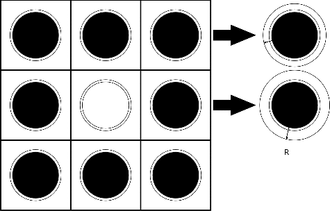
where R is the outer radius of moderator of the 1D cylindrical pin cell. As the Dancoff correction factor is known, the outer radius can be determined by binary search. By this algorithm, the equivalent 1D cylindrical pin cell can be obtained for each fuel pin cell in the lattice system. The white boundary condition for the equivalent 1D pin cell is utilized when searching the outer radius. shows this equivalence procedure.
2.2. The local calculations
2.2.1. Definition of the pseudo resonant nuclide and its cross sections
For an infinite homogeneous system, the neutron slowing-down equation can be written as
(6)
(6)
Assume that scattering is elastic and isotropic in the center-of-mass system and the target nuclide is at rest. The IR approximation is adopted. EquationEquation (6)(6)
(6) can be rewritten as
(7)
(7)
where λk, g is the Goldstein–Cohen factor of nuclide k in group g.
The solution of EquationEquation (7)(7)
(7) is
(8)
(8)
A pseudo background nuclide is defined as atomic weight ratio and potential scattering XS is identical to that of 1H. There is no absorption for the pseudo background nuclide. Then a pseudo resonant nuclide is defined for each pin cell in the lattice system or reactor core to be solved as: the energy-dependent XS of the pseudo resonant nuclide is averaged by number densities of all the resonant nuclides; the number density of the pseudo resonant nuclide is
(9)
(9)
where R is the collection of resonant nuclides;
is the volume averaged number density for resonant nuclide in fuel region. In the following derivation, the volume-averaged number density will be assumed for the resonant nuclides in fuel regions of the pin cell.
For an infinite homogeneous system mixed by the pseudo resonant nuclide and the pseudo background nuclide, the solution of EquationEquation (8)(8)
(8) can be rewritten as
(10)
(10)
where σa, k(u) is the energy-dependent microscopic absorption XS; ;
is the energy-dependent microscopic absorption XS of thepseudoresonant nuclide;
is the energy-dependent microscopic scattering XS of thepseudoresonant nuclide;
is the dilution XS; σb = (λσp)pseudo, g + σ0 is the background XS;
is the energy-dependent microscopic intermediate XS;
is the Goldstein–Cohen factor for the pseudo resonant nuclide and is calculated by preserving (λσp)pseudo, g.
The intermediate XS of the pseudo resonant nuclide is an intermediate variable in this method. The only usage of it is to generate the subgroup weights and partial subgroup XSs in Section 2.2.3, after which the intermediate XS will not be used any more.
2.2.2. XS table generation of the pseudo resonant nuclide
The XS table of the pseudo resonant nuclide is generated by solving 0D neutron slowing-down EquationEquation (6)(6)
(6) over a range of given dilution XS. The nuclides in the 0D slowing-down problem consist of all the resonant nuclides in the pin cell and a pseudo background nuclide. The number densities of the resonant nuclides are the volume-averaged number densities of the pin cell. The number density of the pseudo background nuclide is set to be
for a given σ0. More than 20 points of dilution XSs are needed for generating the table.
EquationEquation (6)(6)
(6) is solved by the hyper-fine energy group method (∼1 M energy groups). The multi-group XS of the resonant nuclides and the pseudo resonant nuclide are calculated according to EquationEquations (11)
(11)
(11) and Equation(12)
(12)
(12) , respectively.
(11)
(11)
(12)
(12)
where x is the XS type, including total, scattering, absorption, neutron production, and intermediate XS; σx, k, g is the multi-group XS for nuclide k; σx, pseudo, g is the multi-group XS for the pseudo resonant nuclide.
The XS tables are prepared online. For fresh fuel, the number densities of resonant nuclides are the same for pin cells with the same enrichment. Therefore, only one XS table is to be generated for pin cells with the same enrichment. But for the case with burn-up, the number densities of resonant nuclides are different for different pins. Because generation of the XS table for every pin is time-consuming, a tabulation–interpolation scheme is applied. The procedure is done for each fresh pin cell type:
| (1) | Sort the pin cells from low burn-up to high burn-up; | ||||
| (2) | Select several pins according to the burn-up, including that of the lowest burn-up and highest burn-up at least; | ||||
| (3) | Generate XS tables for the pseudo nuclides of these selected pins; | ||||
| (4) | Obtain the XS tables for pseudo nuclides of other pins by Lagrange interpolation on the burn-up. | ||||
2.2.3. Physical probability table for the pseudo resonant nuclide
The improvement over the conventional theory is that the physical probability table is derived based on the IR approximation and the implementation of the pseudo resonant nuclide in this paper.
The multi-group intermediate XS of the pseudo resonant nuclide can be written in continuous-energy form and subgroup form as
(13)
(13)
where i is subgroup index; I is number of subgroups.
The physical probability table corresponding to the intermediate XS in group g is defined so as to preserve the multi-group intermediate XS at different background XSs. Apply Equation (10) to Equation (13) and the multi-group intermediate XS of the pseudo resonant nuclide is rewritten in subgroup form as
(14)
(14)
where φg, i is the subgroup flux; σinter, pseudo, g, i is subgroup intermediate XS; Δug, i is the lethargy width of subgroup i; wi is subgroup weight defined as
. Multiply the denominator and numerator of EquationEquation (14)
(14)
(14) by
and EquationEquation (14)
(14)
(14) is written as
(15)
(15)
where ci, i = 0, …, I − 1 and di, i = 0, …, I − 1 are coefficients to be determined. Specifically, the first coefficient of the denominator can be obtained as
. The summation of subgroup weights should be unity so that dI − 1 = 1. Besides, the intermediate XS of the pseudo resonant nuclide when the background XS approaches infinity is
(16)
(16)
Therefore, .
Coefficients ci, i = 0, …, I − 2 and di, i = 0, …, I − 2 can be determined by the method of undetermined coefficients where 2I-2 points of background XS are needed.
(1) Determination of the intermediate subgroup XS
Apply σb = −σinter, pseudo, g, i to EquationEquation (15)(15)
(15) and it is found that the multiplication terms are zero except for ith term. Therefore, EquationEquation (15)
(15)
(15) can be written as
(17)
(17)
EquationEquation (17)(17)
(17) can be simplified as
(18)
(18)
It can be found that − σinter, pseudo, g, i, i = 1, I are roots of EquationEquation (18)(18)
(18) .
(2) Determination of the subgroup weights
The subgroup weight can be determined after knowing all coefficients (ci, i = 0, …, I − 1 and di, i = 0, …, I − 1). In EquationEquation (15)(15)
(15) , the denominators should be equivalent:
(19)
(19)
Apply σb = −σinter, pseudo, g, i to EquationEquation (19)(19)
(19) and it is found that the multiplication terms are zero except for ith term:
(20)
(20)
Therefore, the subgroup weight is calculated by
(21)
(21)
(3) Determination of the partial subgroup XS
The partial subgroup XS, including subgroup total XS, subgroup absorption XS, subgroup scattering XS and subgroup neutron production XS, of the pseudo resonant nuclide and all the component resonant nuclides can be obtained. As the same continuous-energy flux φ(u) is used to obtain the multi-group XS of the pseudo resonant nuclide and all the component resonant nuclides at a particular background XS, the partial multi-group XS of the pseudo resonant nuclide, and all the component resonant nuclides can be written as
(22)
(22)
where x is the reaction type, and k is the nuclide index.
Multiply the denominator and numerator of EquationEquation (22)(22)
(22) by
:
(23)
(23)
where ei, i = 0, …, I − 1 are coefficients to be determined. Specifically, in the same way as the deduction of EquationEquation (16)
(16)
(16) , we can obtain
.
The coefficients ei, i = 0, …, I − 2 can be determined by least square method. Apply σb = −σinter, pseudo, g, i to EquationEquation (23)(23)
(23) and it is found that the multiplication terms are zero except for ith term. Therefore, the partial subgroup XS is determined by
(24)
(24)
(4) Determination of the number of subgroups
The partial subgroup XS for the pseudo resonant nuclide and all the component resonant nuclides, and subgroup weights are named physical probability table in combination. In practice, all the physical probability tables with number of subgroups from 2 to 6 are generated as described earlier and then the final set of physical probability table is selected according to the following two rules:
The subgroup total XS, subgroup absorption XS, subgroup scattering XS, and subgroup weight of the pseudo resonant nuclide is positive.
The root mean square (RMS) error of the subgroup absorption XS is the least within all of the physical probability tables with different number of subgroups. The RMS of the subgroup absorption XS is calculated as
(25)
(25)
2.2.4. Solution of the subgroup fixed-source equation
In a 1D cylindrical system, the neutron slowing-down equation based on the collision probability method can be written as
(26)
(26)
where n and m are region indexes; N is number of regions; Vn is volume for region n; Qm(u) = ∫∞0Σs, m(u′ → u)φm(u')du' is the neutron slowing-down source. Pm → n(u) is the collision probability from region m to the region n. The reciprocity rule is
(27)
(27)
EquationEquations (26)(26)
(26) and Equation(27)
(27)
(27) can be written in subgroup form as
(28)
(28)
and
(29)
(29)
where Σt, m, g, i is the macroscopic subgroup total XS. Pm → n, g, i is the collision probability from region m to the region n where the total cross section is Σt, m, g, i. The collision probability is calculated by the Carlvik's method.
Therefore, the subgroup flux can be obtained as
(30)
(30)
In the fuel regions, the macroscopic subgroup total XS is calculated as
(31)
(31)
While in the moderator regions, the macroscopic subgroup XS is calculated as
(32)
(32)
To be consistent with the physical probability table, the IR approximation is assumed for the neutron slowing-down source, which is calculated by EquationEquations (33)(33)
(33) and Equation(34)
(34)
(34) for fuel regions and moderator regions, respectively.
(33)
(33)
(34)
(34)
Then the linear system EquationEquation (30)(30)
(30) is iteratively solved and the subgroup flux is obtained. The effective self-shielded XS is calculated as
(35)
(35)
2.3. SPH correction for effective self-shielded XS
However, utilization of the effective self-shielded XS directly in afterward multi-group transport calculation will not preserve the reaction rate. Therefore, the SPH correction factor is multiplied to the effective self-shielded XS:
(36)
(36)
The SPH correction was implemented based on the ultra-fine energy group method [Citation15] and the subgroup method [Citation16]. The SPH correction in this paper largely follows the work by Hebert [Citation16]. The SPH correction factor is computed in following procedures:
| (1) | Set μ(0)n, g = 1 in the first step or use the SPH correction factor obtained in last iteration, solve the linear system by Gauss–Seidel iteration:
| ||||
where for fuel regions and
for moderator regions; the neutron slowing-down source in fuel regions and moderator regions are calculated by the following equations:
(38)
(38)
(39)
(39)
| (2) | Compute the SPH correction factor by
| ||||
| (3) | Repeat step (1) and step (2) until the SPH correction factors converge. | ||||
2.4. Overall calculation procedure
The overall calculation procedure of the method is
| (1) | The Dancoff correction factor for each fuel pin cell is calculated by NCM according to Section 2.1; | ||||
| (2) | For each fuel pin cell, the outer radius of the equivalent 1D cylindrical problem is obtained by preserving Dancoff correction factor according Section 2.1; | ||||
| (3) | For each fuel pin cell, a pseudo resonant nuclide is defined by mixing all the resonant nuclides in the fuel region according to Section 2.2.1. The XS tables for all the pseudo resonant nuclides are obtained according to Section 2.2.2; | ||||
| (4) | For each fuel pin cell, the physical probability table of the corresponding pseudo resonant nuclide is obtained through fitting procedure according to Section 2.2.3; | ||||
| (5) | For each fuel pin cell, the subgroup fixed-source equations are formulated based on the equivalent 1D cylindrical problem and the physical probability table of the corresponding pseudo resonant nuclide. The equations are solved by Gauss–Seidel iteration and the self-shielded XSs are obtained according to EquationEquation (35) | ||||
| (6) | For each fuel pin cell, the SPH correction is performed based on the equivalent 1D cylindrical problem as described in Section 2.3. | ||||
3. Numerical results
3.1. Coding system and XS library
The BIM, the RIFM, and the PRNSM based global–local calculation scheme are implemented in a new whole-core transport code NECP-X [Citation17] developed for the high-fidelity reactor physics calculations.
The XS library used by NECP-X consists of multi-group XS library NECL_MG and continuous-energy XS library NECL_CE. NECL_MG is processed in combination of NJOY [Citation18] and RMET21 [Citation19] with the WIMS-69 energy group structure [Citation20] except that the resonance energy range is extended to be from 0.625 to 24 780 eV (energy groups from 13 to 45). The resonance XS tables for the resonant nuclides are generated by RMET21 code.
3.2. UO2 pin cell problem
The reference results in this section are provided by OpenMC [Citation21]. To be consistent with the NECP-X, in which cross sections of some nuclides are from ENDF/B-VI.8 and the others are from ENDF/B-VII, the ACE (A Compact ENDF) format library used is processed from both ENDF/B-Ⅶ.0 and ENDF/B-Ⅵ.8. The cross sections are compared without SPH correction factors.
It is a typical UO2 pin cell, with the pitch to be 1.26 cm. The radius of fuel rod is 0.4095 cm and the outer radius of cladding is 0.475 cm. The materials compositions are given in . The temperatures of the fuel region, cladding region, and moderator region are 293.6 K.
Table 1. Materials compositions of the pin cell problems
The number of subgroups obtained by the fitting procedure described in Section 2.2.3 is given in . The number of subgroups of the physical probability tables generated independently for 238U and 235U are listed. These physical probability tables are used in BIM and RIFM. It is found that the number of subgroups for 238U is 6 except groups 15, 22, and 26. Especially, the number of subgroups is 2 for group 26. This is because there is no resonance in this energy group and the multi-group XS will not change much with the background XS. Therefore, only 2 subgroups can fit the function of multi-group XS against background XS. When the number of subgroups exceeds 2, negative subgroup XSs or negative subgroup weights occur and the first selection rule for the physical probability table is not met. The number of subgroups of groups 15, 16, and 17 is 0 for 235U. This is because the resonance peaks in these groups are narrow and the multi-group XS will not change much with the background XS. In these energy groups, multi-group XSs at typical dilution XSs (800 × 1024 cm2 for 235U) will be used. Number of subgroups for the pseudo resonant nuclide is roughly between that of 238U and 235U. This is because the height of the resonance peaks and the variation degree of the multi-group XS against background XS of the pseudo resonant nuclide are between those of 238U and 235U.
Table 2. Upper energy boundary and number of subgroups for each energy group
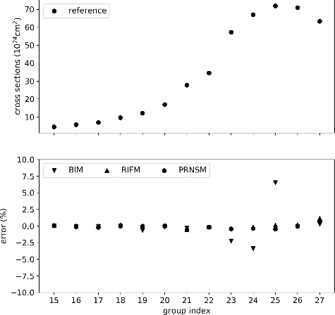
For the UO2 pin cell problem, the errors of pin-averaged 235U absorption cross sections are shown in . It is observed that the cross sections of the 23rd and 24th energy groups are underestimated and the cross section of the 25th energy group is overestimated by the BIM. The errors of RIFM and PRNSM in these energy groups are smaller than those of the BIM. This discrepancy is caused by the resonance interference effect. For other energy groups, the BIM, RIFM, and PRNSM give similar results, the errors of which are small.
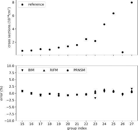
The errors of pin-averaged 238U absorption cross sections are shown in . The maximum error of 238U is smaller than that of 235U. This is because the resonance interference effect is mainly the action of 238U to 235U rather than the other way around as 238U is the dominant resonant nuclide. The BIM underestimates the cross section in the 23rd energy group to 1.5% and overestimates the cross section in the 27th energy group to 1.5%. Another phenomenon that can be observed is that the error of the RIFM in the 25th energy group is larger than that of the BIM and PRNSM.
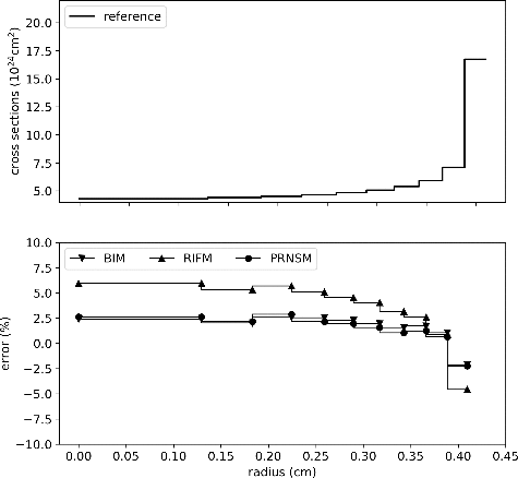
To analyze the phenomenon in detail, the spatially dependent self-shielded cross sections of 238U are compared in . The cross sections of these nuclides increase with the increase in distance to the pin center. For 238U, the BIM and PRNSM overestimate in the inner rings and underestimate in the outer rings. The errors of RIFM are larger than those of the BIM and PRNSM. The RIFM overestimates cross section in inner rings to the extent of 6% and underestimates in outer rings to the extent of 5%. Therefore, though the RIFM can precisely correct pin-averaged self-shielded cross sections, it cannot give precise spatially dependent self-shielded cross sections.
The kinf of the UO2 pin cell problem calculated by different schemes are given in . As the BIM tends to overestimate the absorption cross sections, the kinf is underestimated by 482 pcm. The result of the RIFM is a little bit better than that of the BIM and the PRNSM shows better performance than the RIFM. Though the PRNSM can give relatively precise self-shielded cross sections, the kinf will still be underestimated due to multi-group equivalence effect. When the SPH correction is applied, the kinf is improved by 202 pcm.
Table 3. Comparisons of the kinf of the UO2 pin cell problem
3.3. 3 × 3 Assemblies problem
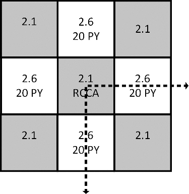
The VERA core physics benchmark [Citation22] Problem #4-2D: 2D HZP BOC 3 × 3 Assembly (Colorset) is analyzed in this section. The configurations of the problem are shown in . 2.1’ and ‘2.6’ mean the enrichment of the fuel are 2.1% and 2.6%, respectively. ‘20PY’ means there are 20 Pyrex rods in the 2.6% enriched assemblies. RCCA is short for Rod Cluster Control Assembly. Problem #4-2D has a series of cases and case 4A-2D is tested in this section. In this case, there is no control rod in RCCA. The detailed information about the benchmark and the reference results (including reference pin powers and the statistical errors) are given in Ref. [Citation22].
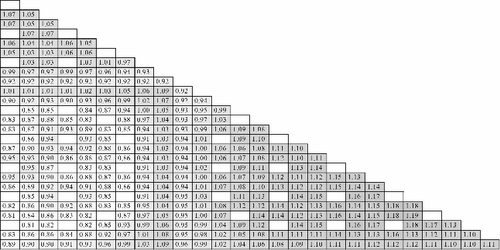
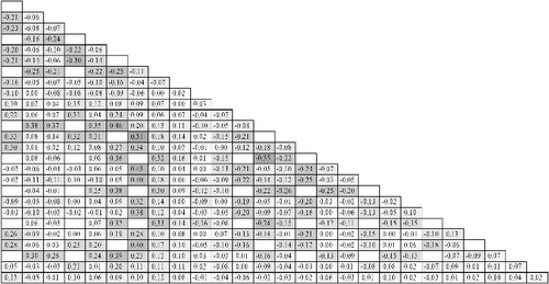
The errors of kinf and pin powers are summarized in . The BIM underestimates the kinf by 300 pcm and the RIFM and PRNSM predict better. The SPH correction improves the kinf by 113 pcm, which is less than those of the pin cell problems. Though the consideration of the resonance interference effect and multi-group equivalence effect will improve the kinf, the pin power errors are not improved obviously. It is found that the RMS and MAX error of pin power is almost the same for all the calculation schemes. The RMS error is around 0.10% and the MAX error is around 0.50%. As the configurations and compositions for the pin cells are similar in this problem, the errors caused by the resonance interference effect and multi-group equivalence effect are close for the pin cells. This makes the kinf different but the power distribution close. The pin powers and the corresponding errors of the PRNSM-SPH scheme are shown in and for different assemblies. The reference pin powers and the statistical errors can be found in Ref. [Citation22,p.151–152]. The pin power errors are calculated by
(41)
(41)
where p is the pin index; PPNECP-X, p is the pin power calculated by NECP-X; PPref, p is the reference pin power.
Table 4. Error comparisons of the 3 × 3 assemblies problem
The computation time is given in . The RIFM consumes the most computation time while PRNSM consumes the least. The 1 G 2D MOC for Dancoff calculation, the 1 G 1D fixed source calculation (including subgroup fixed source calculation and SPH iteration), and the 0D slowing-down calculation consume most of the self-shielding calculation time. The number of the 1 G 2D MOC calculations is 1 for all the schemes. The number of the 1 G 1D fixed source calculations is 62,094 for BIM and RIFM. The number of the 1 G 1D fixed source calculations is almost halved for the PRNSM, and for that the calculations are only performed for the pseudo resonant nuclide. The PRNSM–SPH scheme needs SPH iteration so that more 1 G 1D fixed source calculations are needed. The RIFM needs more 0D slowing-down calculations than PRNSM because the calculations are performed for each nuclide and each pin cell for RIF calculations while the PRNSM only needs 0D slowing-down calculations for each pin type. The PRNSM-SPH is recommended for self-shielding calculation, the computation time of which consumes one-sixth of the overall computation time.
Table 5. Computation time analysis of the 3 × 3 assemblies problem
4. Conclusion
The PRNSM-based global–local self-shielding calculation scheme is described in detail in this paper. Compared to the previous study of heterogeneous-pseudo-resonant-isotope method [Citation11], which combines pseudo-resonant-nuclide method with ESSM, the new method is more efficient, and can obtain spatially dependent self-shielded XS more easily. Furthermore, it uses the homogeneous XSs table instead of the heterogeneous XSs table. So there is no trick to generate the tables.
This method obtains a set of small equivalent 1D problems from the large-scale problem by preserving Dancoff correction factors, and solves the pseudo-resonant-nuclide subgroup problem for every 1D problem to get the effective self-shield XS. From the numerical results, it can be found that the self-shielded cross sections increase as the distance to the center of the fuel region increases, which can be captured by the conventional subgroup method only when there is one resonant nuclide. For the problem containing multiple resonant nuclides, the BIM could not give accurate pin-averaged self-shielded cross sections or space-dependent self-shielded cross sections. The RIFM can predict pin-averaged self-shielded cross sections more accurately than the BIM but cannot capture the spatial dependence of the cross sections. The PRNSM can provide improved results for both of them, and presents smaller kinf errors for the given test. However, these methods have similar accuracy for the pin powers prediction. This is because the configurations and compositions of the pin cells are similar in the VERA (Virtual Environment for Reactor Applications) benchmark. The PRNSM consumes less computation time than the BIM and the RIFM because of less subgroup fixed source calculations and 0D slowing-down calculations. The time of self-shielding calculations consumes about one-sixth of the total calculation time when the PRNSM is applied.
Acknowledgments
This work was supported by the National Natural Science Foundation of China [grant number 11605128], [grant number 11605130]; China Postdoctoral Science Foundation [grant number 2015M580854], [grant number 2016M592797].
Disclosure statement
No potential conflict of interest was reported by the authors.
Additional information
Funding
References
- Joo HG, Cho JY, Kim KS, et al. Methods and performance of a three-dimensional whole-core transport code DeCART. Proceedings of the PHYSOR-2004; 2004 Apr 25–29; Chicago (IL): American Nuclear Society; 2004. Accompanied by: CD-ROM.
- Jung YS, Shim CB, Lim CH, et al. Practical numerical reactor employing direct whole core neutron transport and subchannel thermal/hydraulic solvers. Ann Nucl Energy. 2013;62:357–374.
- Downar T, Kochunas B, Collins B. Validation and verification of the MPACT code. Proceedings of the PHYSOR-2016; 2016 May 1–5; Sun Valley (USA): American Nuclear Society; 2016. Accompanied by: CD-ROM.
- Hébert A. Development of the subgroup projection method for resonance self-shielding calculations. Nucl Sci Eng. 2009;162:56–75.
- Joo HG, Kim GY, Pogosbekyan L. Subgroup weight generation based on shielded pin-cell cross section conservation. Ann Nucl Energy. 2009;36:859–868.
- Park HJ, Kim KS, Hong SG, et al. An improved DeCART library generation procedure with explicit resonance interference using continuous energy Monte Carlo calculation. Ann Nucl Energy. 2017;105:95–105.
- Takeda T, Kanayama Y. A multiband method with resonance interference effect. Nucl Sci Eng. 1999;131:401–410.
- Hebert A. A mutual resonance shielding model consistent with Ribon subgroup equations. Proceedings of the PHYSOR-2004; 2004 Apr 25–29; Chicago (USA): American Nuclear Society; 2004. Accompanied by: CD-ROM.
- Hong SG, Kim KS. Iterative resonance self-shielding methods using resonance integral table in heterogeneous transport lattice calculations. Ann Nucl Energy. 2011;38:32–43.
- Sugimura N, Yamamoto A. Evaluation of Dancoff factors in complicated geometry using the Method of Characteristics. J Nucl Sci Technol. 2006;43:1182–1187.
- Zu T, Zhang Q, Wu H, et al. Heterogeneous pseudo-resonant isotope method for resolved resonance interference treatment in resonance self-shielding calculation. Nucl Sci Eng. 2016;184:495–513.
- Liu Y, Martin W, Williams M, et al. A full-core resonance self-shielding method using a continuous-energy quasi–one-dimensional slowing-down solution that accounts for temperature-dependent fuel subregions and resonance interference. Nucl Sci Eng. 2015;180:247–272.
- Bacha M, Joo HG. Pointwise cross-section-based on-the-fly resonance interference treatment with intermediate resonance approximation. Nucl Eng Technol. 2015;47:791–803.
- Nordheim LW. The theory of resonance absorption. Symp Appl Math. 1961;XI:58.
- Sugimura N, Yamamoto A. Resonance treatment based on ultra-fine-group spectrum calculation in the AEGIS code. J Nucl Sci Technol. 2007;44:958–966.
- Hebert A. The ribon extended self-shielding model. Nucl Sci Eng. 2005;151:1–24.
- Chen J, Cao L, Liu Z, et al. Development of the high-fidelity neutronics and thermal-hydraulic coupling code NECP-X/SUBSC. Proceedings of the M&C 2017; 2017 Apr 16–20; Jeju (Korea): American Nuclear Society; 2017. Accompanied by: CD-ROM.
- MacFarlane RE, Muir DW. NJOY99.0: code system for producing pointwise and multigroup neutron and photon cross sections from ENDF/B data. Santa Fe (USA): Los Alamos National Laboratory; 2000. PSR-480/NJOY99.00.
- Leszczynski F. Neutron resonance treatment with details in space and energy for pin cells and rod clusters. Ann Nucl Energ. 1987;14:589–601.
- Aldama DL, Leszczynki F, Trkov A. WIMS-D library update. Vienna (Germany): International Atomic Energy Agency; 2003.
- Romano P, Forget B. The OpenMC Monte Carlo particle transport code. Ann Nucl Energy. 2013;51:274–281.
- Godfrey A. VERA core physics benchmark progression problem specifications. Oak Ridge (USA): Oak Ridge National Laboratory; 2014. CASL-U-2012-0131-004.

