
 ?Mathematical formulae have been encoded as MathML and are displayed in this HTML version using MathJax in order to improve their display. Uncheck the box to turn MathJax off. This feature requires Javascript. Click on a formula to zoom.
ABSTRACT
In order to evaluate the effect of iodine partial pressure on the iodine stress corrosion cracking (I-SCC) behaviors of a Zr–Sn–Nb alloy, ring tensile tests were conducted at 350 °C and in atmosphere without iodine and with iodine partial pressure of 102, 103, and 104 Pa, respectively. Results show that the maximum load, fracture displacement, tensile strength, and fracture energy of the Zr–Sn–Nb specimens decrease monotonically with the increase of iodine partial pressure. The fracture morphology of specimen with 102 Pa iodine exhibits two different fracture regions. One is the mixture form of ductile and brittle fracture, and the other is only ductile fracture. For the specimen with 103 Pa, stair-shaped fracture surface is formed as a result of the alternative propagation of transgranular cracks and intergranular cracks. The critical iodine partial pressure of the Zr–Sn–Nb alloys is lower than 102 Pa under the present conditions.
1. Introduction
After the first failure of cladding materials on account of pellet–cladding interactions (PCI) was observed in boiling water reactors, PCIs have been considered as the main reason for the failures of zirconium cladding in commercially light water reactor, especially under the power transient condition during the nuclear reactor operation [Citation1–5]. With the increase of burn-up of fuel element, cladding materials will experience a higher hoop stress due to the radiation-induced swelling of fuel pellets, and may be attacked by the aggressive fission products (iodine, cesium, and so on), which can be released from fuel pellets by means of recoil and/or crack channels of fuel pellets. These fission products can cause zirconium cladding to become susceptible to stress corrosion cracking (SCC) [Citation3]. Therefore, it has been believed that iodine-induced SCC (I-SCC) can cause the fracture failures of zirconium cladding under PCI conditions in pressurized water reactors [Citation5,Citation6]. I-SCC of zirconium cladding has been identified by comparing the failure behaviors of zirconium alloys in-pile with that in the out-of-pile tests under the condition with stressing and iodine environment [Citation1,Citation7].
The presence of I-SCC in zirconium alloys may reduce the safety of reactor operations owing to the degradation of ductility of the cladding materials. As a result, many experiments and tests have been conducted to deal with the I-SCC behaviors of zirconium alloys. Many factors can affect the I-SCC behaviors of zirconium alloys, such as external loading, temperature, iodine concentration, irradiation, compositions, microstructure, surface condition, and so on [Citation8,Citation9]. Among them, I-SCC can occur in zirconium alloys only when the iodine concentration reaches a threshold value. Therefore, the critical concentration of iodine to induce I-SCC of zirconium alloys was investigated [Citation10–12]. Peeh et al. [Citation10] believed that the critical concentration was higher than 10−5g/cm3 (about 4 × 10⁻³bar) at 400 °C under out-of-pile testing condition. The critical concentration of iodine increased with the decrease of testing temperature, it increased to 3 × 10⁻⁵ g/cm3 when the testing temperature decreased to 350 °C [Citation12]. However, the estimated pressure of iodine is as low as 10−19bar based on the equilibrium between CsI, UO2, O2, and Cs2UO4 at 600 K by the method of thermodynamic calculations [Citation13,Citation14]. Although the partial pressure of iodine under irradiation was 7 orders of magnitude higher than that of un-irradiation condition due to the dissociation of cesium iodide, according to Konashi's calculations [Citation15], this critical concentration of iodine was much higher than the estimated partial pressure of iodine in-pile [Citation3].
On the other hand, some researchers believed that I-SCC of zirconium alloys might occur under very low iodine pressure condition (10−19 bar), because a monolayer of iodine adsorbed at the crack tip of zirconium alloys could reduce the bonding energy of alloys and lead to a transgranular crack [Citation13,Citation14]. Thus, it is not clear what critical partial pressure of iodine can induce the I-SCC of zirconium alloys at present. The present paper investigates the effect of iodine partial pressure on the I-SCC behaviors of a Zr–Sn–Nb alloy at an elevated temperature. In consideration of the circumferential stresses in cladding materials resulting from the radiation-induced swelling of fuel pellets, the slow-rate ring tensile tests are performed to simulate the circumferential load applied on the Zr–Sn–Nb alloy.
2. Experimental procedure
The cladding alloy used in the present study was Zr–Sn–Nb alloy, which was a new kind of zirconium-based alloys developed by Nuclear Power Institute of China. The nominal chemical composition of Zr–Sn–Nb alloy is shown in . First, the Zr–Sn–Nb alloy was annealed in vacuum to form a recrystallized structure. shows the microstructure of the recrystallized Zr–Sn–Nb alloy, and this alloy has a relatively uniform structure with an average grain size of ∼6 μm and a large number of fine Zr(Fe,Cr,Nb)2 second phases are existed in the alloy. The Zr–Sn–Nb samples were manufactured into the ring specimens with size of 9.5 mm in outer diameter and 0.57 mm in thickness by electric spark cutting, and then the ring specimens used in the test were cut to form the gauge section with size of 3 mm in length and 1.7 mm in width, as shown in . Through this design, the maximal uniform uniaxial hoop strain could be exerted at the gauge section of ring specimens [Citation16]. Prior to the slow-rate ring tensile testing, these ring specimens were washed in a mixed acid (10% HF, 15% HNO3, 30% H2SO4, and 45% HO2, in volume) to remove the grease and oxides, followed by cleaning in pure water and drying with hot air.
Table 1. Chemical composition of the as-received Zr–Sn–Nb alloy
Figure 1. The microstructure of the Zr–Sn–Nb alloy.
Figure 2. The photograph of (a) the ring specimen with gauge section and (b) the assembling type of the ring specimen for the I-SCC experiment.
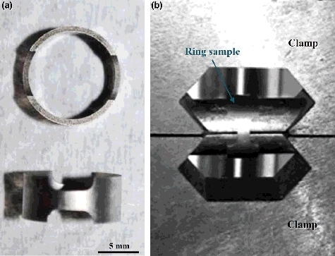
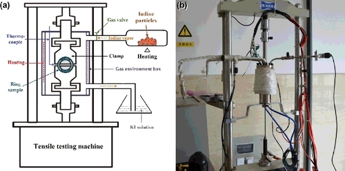
The schematic diagram and photograph of the testing equipment for I-SCC experiments under the ring tensile condition are shown in . The gas environment box, sample clamps, and iodine gas tubes are made of 304 stainless steel. The ring specimens were fixed on the clamps by two semi-cylinders with angled end faces, as illustrated in . With the aid of these mechanical structures, circumferential stresses could be produced in the ring specimens when tensile load was exerted on the clamps. Out of the clamps, a gas environment box was assembled on the LETRY tensile testing machine. By heating the iodine particles, iodine vapor could be generated. Different partial pressures of iodine vapor could be realized by heating iodine particles at different temperatures, according to the relationship between the saturated vapor pressure of iodine and temperature. It should be noted that although iodine vapor could be consumed by the reaction of iodine with gas environment box, sample clamps, and testing specimen during testing process, the partial pressure of iodine could be maintained near the designated value because the iodine vapor could be incessantly generated when the partial pressure was lower than the equilibrium pressure.
Figure 3. The testing equipment for I-SCC experiments under the ring tensile condition. (a) Schematic diagram; (b) photograph of the testing equipment.
At the beginning of I-SCC experiments, pure argon gas was pre-injected to the gas environment box for 8 h to evacuate air, in order to avoid oxidation of Zr–Sn–Nb specimens. The iodine particles were first heated to the designated temperature and then iodine vapor was introduced into the gas environment box. There was a holding time of 30 min before I-SCC experiments began so as to obtain the designated partial pressure in the entire gas environment box. The I-SCC experiments were conducted at 350 °C with a slow stain rate of 10−5/s. The partial pressures of iodine were maintained at 102, 103, and 104 Pa, by heating the solid iodine particles to 40, 65, and 110 °C correspondingly. For the purpose of comparison, the experiment of Zr–Sn–Nb specimen also was performed under condition without iodine vapor. After I-SCC experiments, a FEI NOVA NanoSEM400 scanning electronic microscope was used to observe the fracture morphology of the Zr–Sn–Nb specimens, and the elements of the specimen surface were detected using an OXFORD INCA CH5 energy dispersive spectroscopy (EDS). The microstructure of the as-received Zr–Sn–Nb alloy (etched by an etching solution with H2O:HNO3:H2SO4:HF volume ratio of 10:10:10:1) was also examined by this equipment before the ring tensile testing.
3. Results and discussion
The load-displacement curves of the I-SCC experiments with different partial pressures of iodine vapor are shown in . With the increase of displacement, the loads increase rapidly at the first stage of experiments and quickly reach the maximum value after specimens yield. Then the loads decrease and exhibit an approximately linear relationship with displacement. However, the decrease rate of load is obviously higher than conventional tensile tests of zirconium alloys. This phenomenon is also observed in ring tensile test of the irradiated Zircaloy-4 cladding with approximately 65 GWd/tU burn-up [Citation16]. This difference may be caused by the different deformation behaviors of specimens between the ring tensile test and conventional tensile test.
Figure 4. Load-displacement curves of the I-SCC experiments under different partial pressures of iodine vapor.
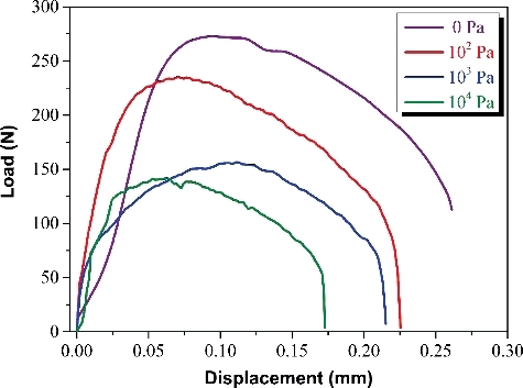
The effect of iodine partial pressure on the tensile behaviors of Zr–Sn–Nb specimens is significant. The Zr–Sn–Nb alloy without iodine vapor shows the highest maximum load and fracture displacement, and both of the maximum load and fracture displacement gradually decrease with the increase of partial pressure of iodine vapor. When the partial pressure of iodine vapor increases from 0 to 102 Pa, the maximum load decreases from ∼275 to ∼230 N, and the fracture displacement reduces from ∼0.26 to ∼0.225 mm. The larger decrease of maximum load and fracture displacement indicates that I-SCC maybe occurred in the Zr–Sn–Nb specimen with iodine partial pressure of 102 Pa. This iodine partial pressure is distinctly lower than the critical concentration pressure of iodine (∼4 × 10² Pa) proposed by Peeh [Citation10]. Therefore, our experimental results preferentially support the opinion that I-SCC of zirconium alloys can occur under very low iodine partial pressure condition [Citation13,Citation14]. With further increase of partial pressure of iodine, the maximum load and fracture displacement of Zr–Sn–Nb specimens continue to decline, demonstrating that higher partial pressure of iodine promotes the I-SCC susceptibility of zirconium alloys. When iodine exists on the surface of zirconium alloys, the gaseous ZrI4 can be produced by the following reaction [Citation17]:
(1)
(1)
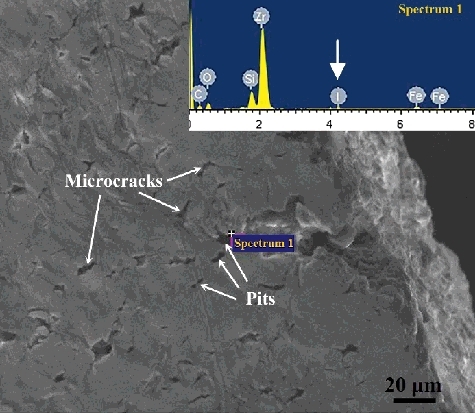
According to the equilibrium relationship of gaseous iodine with Zr/ZrI4, higher partial pressure of iodine facilitates the formation of gaseous ZrI4, and increase the reaction rate of iodine with zirconium. Because zirconium atoms are removed from the matrix by the release of ZrI4, corrosion pits can be formed on the surface of zirconium alloys. These corrosion pits can serve as source of the micro-cracks under the action of tensile stresses. Therefore, the number of micro-cracks is expected to increase with the increase of partial pressure of iodine in the I-SCC experiments [Citation18]. In the present study, many corrosion pits and pits-induced micro-cracks are formed on the specimen surface, as shown in . The EDS analysis reveals that a little of I element exists in the corrosion pit; this indicates that the formation of corrosion pits is related to the reaction of zirconium and iodine. On the other hand, both the critical stress intensity factor of Zr–Sn–Nb alloys and the incubation time for I-SCC initiation decrease with the increase of partial pressure of iodine [Citation19,Citation20]. The ab initio atomic-scale simulations also show that the effective free surface energy of zirconium is reduced by the adsorption of iodine atoms on the zirconium surface, and the reduction values of effective free surface energy increase obviously with the increase of iodine pressure [Citation21]. As a result, the I-SCC susceptibility of Zr–Sn–Nb specimens increases and the maximum load and fracture displacement decrease under the conditions with higher partial pressure of iodine.
Figure 5. The microstructure and EDS analysis of the specimen surface after I-SCC experiment with iodine pressure of 102 Pa.
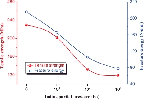
shows the effect of iodine partial pressure on the maximum tensile strength and fracture energy of Zr–Sn–Nb specimens. Fracture energy represents the work done on the specimen during tensile testing, and it equals to the area of the stress–strain curve. The fracture energy and maximum tensile strength can be used to assess the susceptibility of I-SCC of zirconium alloys [Citation5]. Both maximum tensile strength and fracture energy decrease monotonically with the increase of the partial pressure of iodine vapor; these results also demonstrate that higher partial pressure of iodine promotes the susceptibility of I-SCC of Zr–Sn–Nb alloys.
Figure 6. The maximum tensile strength and fracture energy of Zr–Sn–Nb specimens as function of the partial pressure of iodine vapor.
The low magnification fracture morphologies of Zr–Sn–Nb specimens at different partial pressures of iodine are shown in . The specimen without iodine vapor possesses an attractive ductility; it has an obvious necking deformation at the gauge section before fracture, as shown in . The high magnification fracture morphology of the Zr–Sn–Nb specimen without iodine () shows that many dimples are formed on the fracture surface, and demonstrates a typically ductile fracture. In the case of specimen with iodine partial pressure of 102 Pa, the fracture morphology exhibits two different fracture regions. One is the mixture form of ductile and brittle fracture, which is mainly located at the two sides of the fracture surface; these regions present a mixture behavior of transgranular fracture and ductile fracture, and the transgranular fracture and ductile fracture occur alternately, as shown in . These regions are possibly formed by the following mechanisms. During the ring tensile testing, sharp micro-cracks are produced under the coaction of both tensile stresses and the irregularly shaped pits induced by the corrosive iodine vapor. Our experiments have observed the micro-cracks and pits on the specimen surface, as shown in . The sharp micro-crack can lead to a higher stress intensity factor in the local region nearby crack tips, and resultantly generates a transgranular crack at the front of the original micro-crack [Citation22]. Because the concentration of iodine is relatively lower, there is not enough time to react of iodine with the zirconium atom at the crack tip when the micro-crack has expanded. On this occasion, the crack tip becomes blunt as a result of plastic deformation of zirconium matrix nearby the crack tip. Subsequently, the stress intensity factor will reduce and the fracture behavior of ring specimen turns into ductile fracture. When sufficient iodine atoms diffuse to the crack tip and react with zirconium matrix, the fracture behavior transforms into the transgranular fracture again. These processes possibly result in the mixture fracture behaviors at the two sides of fracture surface. The other is only ductile fracture at the center region of fracture surface. After the two sides of specimen fractured, lager enough stresses are exerted on the small center cross-section of the testing specimen, and this results in the ductile rupture [Citation3].
Figure 7. The low magnification fracture morphologies of Zr–Sn–Nb specimens at different partial pressures of iodine. (a) Without iodine; (b) 102 Pa; (c) 103 Pa; (d) 104 Pa.
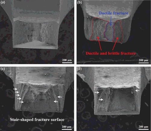
Figure 8. The high magnification fracture morphologies of Zr–Sn–Nb specimens at different partial pressures of iodine. (a) Without iodine; (b) 102 Pa; (c) 103 Pa; (d) 104 Pa.
With the increase of iodine partial pressure, the reaction rate of iodine with zirconium increases accordingly, and the fracture behavior of the ring specimen completely turns into brittle fracture when the partial pressure of iodine reaches 103 Pa, as shown in . Different from other specimens, a stair-shaped fracture surface is exhibited in this specimen. The formation of stair-shaped fracture surface possibly results from the crystallographic texture of zirconium alloy tube formed during rolling process. It is well known that most of the textures in zirconium alloy tubes are the basal texture with a (0002)/⟨1120⟩ crystal relationship [Citation23]. Our previous study has shown that the Zr–Sn–Nb alloy tube possesses the same texture. According to the crack nucleation and growth models in zirconium alloys proposed by Park [Citation22,Citation24,Citation25], a cleavage crack (transgranular crack) can be formed on the cleavage habit planes. The cleavage crack can be generated at a low stress intensity when the corrosion pits and associated micro-cracks are arranged on a cleavage habit plane. It is generally believed that basal plane (0002) are the cleavage habit planes in the zirconium alloys [Citation1,Citation26]. Therefore, the cleavage transgranular crack can be extended successively in the Zr–Sn–Nb alloy tube with basal texture. However, when the cleavage transgranular crack encounters some grains with different orientations, this crack cannot continue to traverse these grains, and then stops at the grain boundaries of these grains [Citation22]. With the aid of corrosive iodine vapor, intergranular cracks can occur at the front of the cleavage transgranular crack, and the propagation direction of the crack has been changed. In this way, a stair with intergranular cracks can be formed on a cleavage transgranular crack. shows the morphology of the fracture surface at the region of stair; many intergranular cracks can be distinctly observed. This experimental phenomenon demonstrates that the fracture stair is formed by the propagation of intergranular cracks.
When the partial pressure of iodine further increases to 104 Pa, the stair-shaped fracture surface becomes less obvious and most of the cracks belong to the transgranular crack, as shown in and (d). This is because there are sufficient iodine atoms diffusing to the crack tip at any time under such high partial pressure when the transgranular cracks propagate. Although there are some grains with unfavorable orientations located at the front of intergranular cracks, they still can move through these grains as a result of the higher erosion rate of iodine on the zirconium matrix near the intergranular crack tip. Therefore, this specimen has the lowest tensile resistance and exhibits the lowest tensile strength and ductility.
4. Conclusions
| (1) | With the increase of iodine partial pressure, the maximum load and fracture displacement of the Zr–Sn–Nb specimens decrease gradually because higher partial pressure of iodine promote the I-SCC susceptibility of zirconium alloys; the maximum tensile strength and fracture energy also decrease monotonically. | ||||
| (2) | For the iodine partial pressure of 102 Pa, the fracture morphology exhibits two different fracture regions. One is the mixture form of ductile and brittle fracture at the two sides of fracture surface, and the other is only ductile fracture at the center region of fracture surface. | ||||
| (3) | Stair-shaped fracture surface is formed on the Zr–Sn–Nb specimen with iodine partial pressure of 103 Pa as a result of the alternative propagation of transgranular cracks and intergranular cracks. With further increase of partial pressure of iodine, the transgranular cracks are more prevalent. | ||||
| (4) | Based on the experimental results, the critical iodine partial pressure of the Zr–Sn–Nb alloys is lower than 102 Pa under the present conditions. | ||||
Disclosure statement
No potential conflict of interest was reported by the authors.
References
- Cox B. Pellet-clad interaction (PCI) failures of zirconium alloy fuel cladding – a review. J Nucl Mater. 1990;172:249–292.
- Fournier L, Serres A, Auzoux Q, et al. Proton irradiation effect on microstructure, strain localization and iodine-induced stress corrosion cracking in Zircaloy-4. J Nucl Mater. 2009;384:38–47.
- Yang TT, Tsai CH. On the susceptibility to stress corrosion cracking of Zircaloy in an iodine containing environment. J Nucl Mater. 1989;166:252–264.
- Kim JH, Lee MH, Choi BK, et al. Effects of oxide and hydrogen on the circumferential mechanical properties of Zircaloy-4 cladding. Nucl Eng Des. 2006;236:1867–1873.
- Yan M, Yin Q, Wang P, et al. I-SCC behavior evaluation of N36 zirconium alloy cladding using ring tensile test. Rare Metal Mater Eng. 2015;44:58–61.
- Choo K, Pyun S, Choi J. A study on the mechanism of iodine-induced stress-corrosion cracking of Zircaloy-4. J Nucl Mate. 1987;149:289–295.
- Cox B, Wood JC. Iodine-induced cracking of Zircaloy fuel cladding – a review. Proceedings of the Symposium on Corrosion Problems in Energy Conversion and Generation. October 15-17; New York, USA: Electrochemical Society; 1974.
- Nikulin SA, Rozhnov AB. Corrosion cracking of zirconium cladding tubes (a review). I. Methods of study and mechanisms of fracture. Met Sci Heat Treat. 2005;47:71–79.
- Nikulin SA, Rozhnov AB. Corrosion cracking of zirconium cladding tubes. A review. 2. Effect of external factors, structure, and properties of the alloys. Met Sci Heat Treat. 2005;47:427–433.
- Peeh M, Stehle H, Steinberg E. Out of pile testing of iodine stress corrosion cracking in Zircaloy tubing in relation of the pellet-cladding interaction phenomenon. In: Schemel JH, Papazoglou TP, editors. Zirconium in the Nuclear Industry. Philadelphia, USA: ASTM International; 1979.
- Busby CC, Tucker RP, McCauley JE. Halogen stress corrosion cracking of zircaloy-4 tubing. J Nucl Mater. 1975;55:64–82.
- Garlick A, Wolfenden PD. Fracture of zirconium alloys in iodine vapour. J Nucl Mater. 1971;41:274–292.
- Cubicciotti D, Jones RL, Syrett BC. Chemical aspects of iodine-induced stress corrosion cracking of zircaloys. In: Franklin DG, editor.Zirconium in the Nuclear Industry. Philadelphia, USA: ASTM International; 1982.
- Sidky PS. Iodine stress corrosion cracking of Zircaloy reactor cladding: iodine chemistry (a review). J Nucl Mater. 1998;256:1–17.
- Konashi K, Yato T, Kaneko H. Radiation effect on partial pressure of fission product iodine. J Nucl Mater. 1983;116:86–93.
- Kim SK, Bang JG, Kim DH, et al. Mechanical property evaluation of high burn-up nuclear fuel cladding using the ring tensile test. Met Mater Int. 2009;15:547–553.
- Cubicciotti D, Jones RL, Syrett BC. Chemical aspects of iodine-induced stress corrosion cracking of zircaloys. In: Franklin DG, editor.Zirconium in Nuclear Applications. Philadelphia, USA: ASTM International; 1982.
- Cubicciotti D, Howard SM, Jones RL. The formation of iodine-induced stress corrosion cracks in zircaloys. J Nucl Mater. 1978;78:2–16.
- Dai X, Zhao W, Wang Y. The I-SCC behavior of N18 alloy at constant strain rate. Proceedings of the IEEE International Conference on Advancements in Nuclear Instrumentation Measurement Methods and their Applications. IEEE, Marseille, France, June 7-10; 2009.
- Peng Q, Zhao WJ, Li WJ, et al. Effect of iodine on the stress corrosion cracking of N18 zirconium. Corros Sci Prot Technol. 2005;17:27–30. Chinese.
- Legris A, Domain C. Ab initio atomic-scale modelling of iodine effects on hcp zirconium. Philos Mag. 2005;85:589–595.
- Park SY, Kim JH, Lee MH, et al. Effects of the microstructure and alloying elements on the iodine-induced stress-corrosion cracking behavior of nuclear fuel claddings. J Nucl Mater. 2008;376:98–107.
- Tenckhoff E. Deformation mechanisms, texture, and anisotropy in zirconium and zircaloy. STP966. Philadelphia (PA): ASTM; 1988.
- Park SY, Kim JH, Lee MH, et al. Stress-corrosion crack initiation and propagation behavior of Zircaloy-4 cladding under an iodine environment. J Nucl Mater. 2008;372:293–303.
- Park SY, Kim JH, Choi BK, et al. Crack initiation and propagation behavior of zirconium cladding under an environment of iodine-induced stress corrosion. Met Mater Int. 2007;13:155–163.
- Jones RL, Cubicciotti D, Syrett BC. Effects of test temperature, alloy composition, and heat treatment on iodine-induced stress corrosion cracking of unirradiated zircaloy tubing. J Nucl Mater. 1980;91:277–292.