
ABSTRACT
Most of the modern main control rooms of nuclear power plants are equipped with computer-based operating procedures (CBPs), which make it easier for operators to operate and control the reactor compared with paper-based operating procedure (PBP). However, most of the CBPs do not provide necessary information which is useful for operators, especially in an emergency situation. In addition, proper decisions and actions of the procedure steps are needed to prevent human errors in mitigating the accident. The additional information, which is the information of the impact of a counter action (by automatic system and human actions) such as the components influenced and future plant behavior will be very helpful for operators to understand the effects of the counter action. The aim of the study is to develop techniques to generate the additional information. Multilevel flow modeling (MFM) is applied to model a nuclear power plant and the counter actions described in CBPs. A simple emergency operating procedure of steam generator tube rupture accident of a pressurized water reactor (PWR) plant is used as a case study. The algorithm to generate the additional information is based on the influence propagation rules and cause–effect relations expressed in the MFM model of the PWR plant.
1. Introduction
Computer-based operating procedures (CBPs) have been developed for many years to overcome the drawbacks of paper-based operating procedures (PBPs). Most of the modern and advanced main control rooms of nuclear power plants have been equipped with CBPs. The CBPs are intended to help operators and to reduce their cognitive errors, for example, by providing dynamic information representation; providing navigational link to other related procedures; and procedures’ path-tracking. Moreover, in CBPs, the information can be displayed either as individual parameter display or in processed form and more interactively [Citation1]; for example, information about the status of plant parameters, trend plots, status of equipment, and integration of several indications in a compact form [Citation1].
Comparing with the PBPs, CBPs display the information via visual display units (VDUs) and are located on the operators’ console desks. Some studies have been conducted to compare ‘computer’ and ‘paper’ in case of conducting tasks and reading the information [Citation2,Citation3]. The studies found that both ‘computer’ and ‘paper’ have benefits and drawbacks depending on the type of tasks and the required outcomes of the task.
Related with the VDU used in CBPs, reading information on the VDU is not as easy as the information on papers because the limited information displayed on the VDU [Citation4] may cause operators lose a sense of their current position in completing the procedure steps. In addition, human reliability and response will be reduced because reading on the VDU is slower and more fatiguing [Citation5]. Moreover, some procedures were made based on the knowledge of experts without considering the knowledge level and the needs of operators during their jobs to monitor and control the reactor. It will make it difficult for operators to understand the procedures. Literature [Citation6,Citation7] mentioned that more than 18% of accidents were caused by the miss-follow of procedures due to the complexity and the understandability factors of procedures. In order to reduce human errors, additional information should be provided which would help the operators understand the purpose of each procedure step.
Le Blanc et al. [Citation8] conducted a study of the requirements for CBP for operators. The study was conducted by giving some questions to operators related with the use of CBP. In addition, some experiments have been conducted to investigate the impact of CBP on operator performance. The results of the study then can be made as recommendations for requirements of designing CBP. Some of the results require that CBPs should ease the identification and support assessment of the expected plant and equipment response; provide detailed information (if available); and provide high-level information related to procedure goals.
In addition, literature [Citation9] mentioned that the design of human machine interface, in this case CBP, especially for operating a plant in a critical situation should meet the operator needs. In addition, operators should understand the system as an object of action and recognize the intention of counter action (automatic or human action). Moreover, Fujii et al. [Citation10] conducted a study related with Process Kiken Yochi (PKY), an activity which makes training operators in Japanese chemical plants to affirm the knowledge of plant condition diagnosis based on alarm event. The study proposed a software tool that utilizes the information provided in PKY sheet to support the operation in anomalous plant condition. One of the important information displayed on the tool is future plant behavior and counter actions of an anomaly cause.
Furthermore, Hollnagel et al. [Citation11] mentioned about anticipating, which is one of the four cornerstones of resilience (responding, monitoring, anticipating, and learning). The ability to anticipate is related with finding out and knowing what to expect further. In case of an emergency condition, it includes the ability to determine the potential disturbance; change the operation conditions; or future plant behavior.
The above four references discussed about the information and the kind of information needed by operators and also the ability of system to provide the information in an emergency condition. The purpose of providing the information is to increase the awareness of operators about the impact of counter actions (automatic or human actions) and then reduce human errors. Therefore, it can be justified that the information provided by the proposed system (components influenced and future plant behavior) can be useful for reducing human errors in plant operations. Based on the information, they will take into account the affected components and prepare actions to anticipate unintended conditions.
Displaying functional information is proposed as one of the desirable features of the CBP [Citation12]. In this paper, multilevel flow modeling (MFM) [Citation13–15] is used to model the counter actions (by automatic systems or human actions) of the operating procedure by considering the following reasons. MFM is a method to represent a complex industrial system in terms of functions and objectives and the interconnection among them in high level of abstraction. Unlike other object-oriented modeling, MFM offers some benefits. In other object-oriented modeling (such as Unified Modeling Languange (UML) or hierarchical colored Petri-net), as mentioned in [Citation16], the validity of diagnosis result is the main focus and the diagnosis process is not revealed to the operators. It means that operators do not understand what happened in a diagnostic system based on other-oriented modeling techniques. On the other hand, MFM provides comprehensive diagnosis based on human perspective of the objective of the system. MFM breaks down the system into means–ends and whole–part dimension. In the means–ends dimension, MFM depicts the relationships among functions to achieve the system objective. On the other hand, the system is described in different levels of aggregation in the whole–part dimension. In addition, MFM provides realization relation which corresponds physical components with their functions, for example, the function of transporting water can be realized by a pump. Furthermore, another important aspect of MFM is its ability to conduct consequence reasoning which is very useful for assessing the plant situation and system performance. The consequence reasoning is based on influence propagation, which indicates that the change of state of a function or objective will change the state of other neighboring functions or objectives (downstream connections). Regarding this study, the consequence reasoning and influence propagation are very useful to comprehensively gather the proposed additional information (components influenced and future plant behavior).
In this study, an MFM model of a simple pressurized water reactor (PWR) plant is used. In addition, an MFM control function is applied to the MFM model to model the counter action (by automatic system or human action) following instructions in the procedure steps of emergency operating procedure (EOP). In this case, for investigation purposes, a simplified EOP of steam generator tube rupture (SGTR) accident of PWR plant is used. Then, by implementing consequence reasoning and influence propagation [Citation17] to the MFM model, the information about the components influenced and future plant behavior can be derived. Algorithms are proposed to generate the additional information and to display the explanation sentences of the information.
2. Multilevel flow modeling
2.1. Overview of multilevel flow modeling
MFM [Citation13–15] was developed to model a complex plant system in terms of goals, functions, multiple levels of means–end and part–whole abstraction [Citation18]. The means–end concept is used to model the system functions (means) to achieve the goal/subgoals (end). In addition, in the part–whole concept, systems can be represented as a whole or as subsystems in a hierarchical way [Citation19]. Gofuku [Citation20] mentioned that by changing the abstraction level, it will make it easier to deal with a complicated system such as nuclear power plants for designing and managing the abnormal situation of the system. MFM has been implemented, for example, for operator support system in supervisory control [Citation21,Citation22] and dynamic operation permission system [Citation23,Citation24]. In addition, MFM can be used to express the information related to plant condition in linguistic form. This functional information is very important for supporting the operators conducting their tasks to monitor and control the plant.
shows the MFM symbols used for constructing an MFM model [Citation15]. The symbols consist of function primitives (such as source, transport, and storage) and relations (influence, means–end, and control). The function primitives correlate with the plant components. For example, a transport function is correlated with a pipe and a tank is represented by a storage function. An MFM model generally consists of mass flow structures, energy flow structures, control structures, and objectives. Each function primitive is connected by influence relations (influencers and participants). On the other hand, means–end relations are used to connect between flow structures (means) and their objectives (ends).
Figure 1. MFM symbol.
2.2. MFM control functions
A counter action (automatic or human action) is an action which changes (produces) or maintains the state of components or systems based on the state or parameter value of the observed components. The action, which is part of the control function, is intended to bring the system back to normal operation. An example is starting the pump to fill water in the tank when the water level reaches the predefined lowest level. Then, the pump is stopped when the tank is fully filled with water.
MFM which represents a complex industrial plant in terms of functions and objectives also accommodates the control function. This paper utilizes the MFM control function to model the counter action. Literature [Citation14,Citation18] gives detailed examples of control function. Literature [Citation14] also describes several types of control functions in MFM as can be seen in . Because a counter action will change the state or create a new state of a function primitive, the basic control function for modeling the counter actions in this paper is the steering (producing) control function.
Table 1. MFM control functions
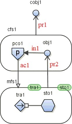
, following the modeling idea proposed in [Citation14], shows an example of a part of an MFM model of water tank system (mfs1) which is controlled by the control function cfs1. In the figure, only the relevant function primitives in the mass flow structure mfs1 are shown. The explanations of the control function are as follows. The objective of the control system (represented by obj1) is to monitor or observe the level of water in tank (represented by storage function sto1). The deviation of the level of sto1 (lower or higher than the predefined level) produces a new state of sto1. This is represented by the produce relation (pr2) between sto1 and obj1 and then set as operation knowledge. Then, the operation knowledge will activate the steering function pco1 (indicated by influence relation in1) to change the state of transport function tra1 using actuate relation ac1. In physical component, it is realized by controlling the pump (ON or OFF) which fill water into the pump. If the state of tra1 has been changed by pco1, it can be said that the objective ‘to control the pump (tra1)’ is achieved. This type of control function is used in this paper.
Figure 2. Control function in MFM.
2.3. Definition of the states of MFM symbols
The definition of the states of MFM is based on [Citation25]. However, in this paper, some modifications have been proposed in order to cover some conditions in real plants. Such modification, for example, is to treat ‘no flow’ in ‘transport’ function primitive, which indicates that there is no mass/energy transferred from one component to another component. shows the modified definition of the states of MFM symbols. The underlined states indicate the modified parts of the definition. The ‘no volume’ state is additionally defined to treat the no liquid mass condition of a tank-type component.
Table 2. Definition of the states of MFM symbols
2.4. Influence propagation
The concept of cause–effect relation is implemented in MFM. The usage of cause–effect concept was proposed by the study to generate plausible counter operations based on MFM models created by the past symbol set [ 26]. Because this study uses the current symbol set of MFM, the rules of influence propagation proposed in the literature [Citation27] are used; there are two types of cause–effect relations: direct and indirect influence. In a direct influence, the state change of a function primitive, for example, transport function will cause state changes of neighboring functions connected to the transport function. On the other hand, in an indirect influence, the state change of a function primitive is caused by other functions. The concept is the basis for influence propagation rules. depicts the influence propagation in an MFM model [26].
Figure 3. Influence propagation.
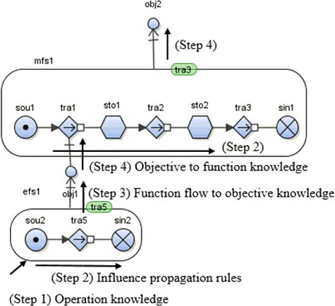
First of all, in Step 1, an action on a component will change the state of the function primitives that is realized by the component. The state change in qualitative level is given by an operation knowledge that correlates an action of a component with a state change of the function realized by the component. An example of the operation knowledge is that closing a valve changes the state of correlated transport function from ‘normal’ to ‘no flow.’ The state change then influences the downward function primitives in the function structure that the function primitives belong to (Step 2). Moreover, by using the knowledge that correlates a function flow with an objective (Step 3), the change of function state will influence the objective connected to the function by a means–end relation in . On the other hand, the objective is also connected to a function by a control relation. The state change of the objective will influence the state of the function. Then, the state change influences the states of all related function primitives (Step 4). Therefore,, the change of the state of a function primitive correlated with the component that a counter action (by automatic system or human operators) is made will influence the states of function primitives, objectives, and then propagate the influence in some parts of system.
As an example of the influence propagation rules, an MFM model of tank process is used, in which the model is similar to the MFM model in . In this case, efs1 represents the energy flow in the pump and obj1 is the objective to keep the pump running. The water flow in the tank is represented by mfs1, while the main objective to maintain the correct water level in the tank is represented by obj2. Initially, all of the states of function primitives are in normal condition and the objectives are enabled. In order to describe the influence propagation rules, let no electrical energy be supplied to the pump. It is indicated by no output flow potential in sou1 (operation knowledge). The state change of sou1 will influence the downstream connections, tra5 and sto2, to change from normal flow to no flow and from normal to no input flow, respectively. Because there is no energy flow in the pump, the objective obj1 ‘to keep the pump running’ cannot be achieved. The failure of achievement of obj1 will disable the tra1 (pump) and change the state from normal flow to no flow. It means that there is no water flow from the pump. This condition then changes the state of all downstream connections from normal to no flow. It indicates that the tank is not filled with water which causes the objective obj2 ‘to keep the level in the tank’ to not be achieved.
3. Algorithm to generate the additional information
As mentioned in the previous section, the additional information related with the impact of an automatic system operation and human action is very important and the information can help operators to understand and follow the procedure steps. This section proposes the algorithms to generate the additional information: components influenced and future plant behavior. The algorithms apply the influence propagation described in Section 2.4 based on an MFM model.
3.1. Components influenced
shows the algorithm to generate the components influenced information as a consequence of a counter action (automatic or human action) following the instructions of an EOP. The explanation of the algorithm is as follows. As described in Section 2.2, the counter action is represented by the ‘control function’ in an MFM model. Each operation in an EOP is in advance correlated with a control function structure. The correlation is made by ‘operation knowledge.’ The knowledge is composed of the name of operation, control flow function corresponding to the operation, and state modifier to express the change of the state of the function primitive that is controlled by the operation. In the case of automatic operation, the ‘operation knowledge’ is the low pressurizer level of pressurizer (‘storage,’ ‘low volume’) that will initiate safety injection (SI) in case of an accident in PWR plants. The operation knowledge is correlated with the obj1 of the MFM control function of which will actuate the control function pco1 to set or change the state of the controlled function primitive.
Figure 4. Algorithm to derive the components influenced.
The next step is to propagate the state change of downward function primitives in the function flow structures that include the affected function primitive using influence propagation. If there is a relation with other function flow structures by ‘means–end relations,’ the influence is propagated to the function flow structures. Then, the influence propagation can be expressed by using ‘explanation sentences’ which describe the state change of function primitives (function components) and the state change of physical components (realized components). The realized components are identified using ‘realization relations’ that correlate functions primitives with the physical components. The ‘realization relations’ contain a list of function primitives and their correlations with the physical components and related mass or energy flow structure, using the following format:
Realization relation: (’function primitive;’ ‘physical component;’ ‘mass/energy;’ ‘object name’)
For example, a storage function (sto) is correlated with a tank and water stored in the tank. In this case, the realization relation can be expressed as (‘sto;’ ‘tank;’ ‘mass;’ ‘water’).
The explanation sentences can be generated using the following pattern:
(a) Function primitives
(State of function primitive) ± ‘of’ ± ‘mass/energy’ ± ‘in’ ± (function primitive)
(b) Realizing the components of function primitives
(State of function primitive) ± ‘of’ ± (object name of mass/energy) ± ‘in’ ± (physical component)
In the pattern, ‘mass’ is used if the function primitive is included in a mass flow structure, and ‘energy’ is used if it is included in an energy flow structure. The converted explanation sentences are sometimes not natural English expressions due to the simple conversion technique. However, an operator will understand the meaning.
Finally, from the explanation sentences of pattern (b), the influenced components are selected and collected. The ‘main components’ database is provided for selecting and collecting the influenced components from the explanation sentences. If the influenced components are in the list of ‘main components’ database, they are set as components influenced and written using the following format:
The components influenced: (‘influenced physical components’)
3.2. Future plant behavior
The counter action (automatic or human action), as mentioned in the previous section, impacts the conditions of system components. Consequently, the future plant behavior is also changed because of the operation actions. By the use of an MFM model, the plant behavior can be correlated with the achievement of function objectives or the change of the states of function primitives in a system. Information about future plant behavior is also important for operators to understand the consequence of procedure steps.
The algorithm to derive the future plant behavior is provided in . To begin with, the first five steps are similar to the algorithm for deriving the components influenced (). Therefore, the explanation sentences made by the algorithm to derive the components influenced are partially used by this algorithm. However, only the explanation sentences of pattern (b) of Section 3.1 are considered.
Figure 5. Algorithm to derive the future plant behavior.
The next step is to select and collect one main explanation sentence for each component from the explanation sentences for the component considering the main function. Main function means a system or a component which is important for safety and should be considered by operators. Then, the explanation sentence is made by setting suitable terms that represent the plant behavior to the parts of the following sentence pattern:
(State of function primitive) ± ‘of’ ± (object name of mass/energy) ± ‘in’ ± (physical component)
Furthermore, special technical terms expressing plant behavior, which are derived from operational procedures or accident management, such as SI, reactor trip, etc. are also stored in a database called ‘specific term’ database that correlates a term with the state of function primitive. For example, the specific term ‘hot shutdown’ can be given for some plant behavior such as reactor trip (no flow of heat in reactor vessel), turbine trip (no flow of mechanical energy in turbine), and generator trip (no flow of electrical energy in generator), and so on. Finally, based on the algorithm in , if some state changes of influenced components are matched with the ‘specific term’ database, then the future plant behavior is expressed in specific technical term. Otherwise, if they are not matched, the future plant behavior is expressed using the selected sentences for components.
4. Case study
4.1. EOP of SGTR
In order to show the applicability of the proposed techniques, an EOP for SGTR of PWR plant, which is a simplified EOP of the SGTR accident of Mihama Unit 2 [Citation28], is used. shows the steps of the EOP. The reason for choosing the SGTR accident is because it is one of the common and potential accidents in PWR plants. Common causes of the SGTR accident are the degradation and aging process and also stress corrosion cracking [Citation29].
Table 3. Simplified EOP of SGTR accident [Citation22]
The SGTR accident should be mitigated following some safety functions: reactor trip, core cooling, steam generator overfill prevention, and steam generator isolation. Operators should follow all the steps in the EOP. This study only investigates some steps which represent the automatic system operations (Step 1: reactor trip and SI) and human actions (Step 3: identify and isolate the ruptured steam generator (SG)).
4.2. MFM model of PWR plant
In order to investigate how the MFM can model the human actions on an EOP and how the proposed algorithms generate the necessary information of the impacts of the actions, a simple MFM model of a PWR plant is constructed, as provided in . This model is a modification of the MFM model developed by Gofuku et al. [Citation30]. The MFM model includes major PWR systems (primary system by mass flow structure mfs1 and secondary system by mfs2) and safety systems (emergency core cooling system, residual heat removal system, and internal spray system). describes some main flow structures, functions, and objectives which will be discussed in this paper.
Figure 6. The MFM model of PWR plant in normal condition.
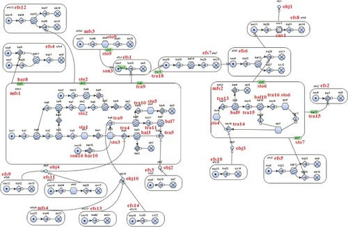
Table 4. Main flow structures, components, and objectives of the MFM model
The main objective (obj1) of the MFM model of the PWR system is to generate electricity. It can be accomplished by converting heat energy into electrical energy. Initially, the heat is generated by the fuel (sou3 in efs1) installed in the reactor vessel (sto3 in mfs1) and by the fission reaction (represented by the energy flow structure efs1). The heat is transferred from the primary system to the secondary structure (efs7) through the steam generator bal14 (primary side) and sin3 (secondary side). Furthermore, the heat is converted into mechanical energy in efs6 to rotate the turbine and generator (efs8). Finally, electrical energy is produced (obj1).
4.3. Explanation of plant behavior based on MFM model
The automatic operation and human actions are expressed in the MFM model. Then, by implementing the influenced propagation rules and the algorithms to generate the additional information, the impacts of the counter actions to the plant behavior can be investigated. The automatic operation is represented by ‘Reactor trip operation,’ while the ‘Isolate Ruptured Steam Generator’ is the example of human action.
4.3.1. Explanation of MFM model for ‘reactor trip’ operation
Reactor trip occurs due to low pressurizer pressure level and automatically trips the turbine and main feedwater system. It will decrease the core power to decay the heat levels, terminate the steam flowing through the turbine, and actuate the steam dump (turbine bypass). During an accident, the reactor trip is automatically done by the safety system. Reactor trip is indicated by the insertion of control rods to the reactor core. The control rods will absorb the neutrons for producing fission reaction and stop heat production in the reactor core.
shows the related part of MFM model with reactor trip operation. The control function cfs1 is used to actuate the control rod (mfs3) to stop the fission reaction and heat production (cobj1). The control rods are inserted if the pressurizer pressure level (sto5) is low. Therefore, the parameter to be observed is the pressurizer pressure level (obj5). The process of reactor trip operation can be explained using the state changes of function primitive by influence propagation.
Figure 7. The MFM model of reactor trip operation.
The component influenced due to the reactor trip operation can be determined using the algorithm described in Section 3.1. The operation knowledge includes reactor trip operation (full control-rod insertion), control structure cfs1, and low volume state in sto5 as a state modifier. The state modifier will actuate the control function pco1 in cfs1 to change the state of tra41 from ‘no flow’ to ‘high flow.’ The high flow of tra41 causes ‘low/no volume’ in sou3 in efs1 that corresponds to no heat generation in the reactor core region. Then, based on influence propagation, there is no energy flow through tra18 to sin5 in efs1. Moreover, the influence propagated to efs7 changes the state of sou10 to ‘low/no output flow potential’ and to ‘low/no flow’ in tra29. Consequently, the efs6 has no energy flow because of ‘no output flow potential’ in sou9 and ‘no flow’ in tra26. The final influence is: because there is ‘no flow’ in tra26 and ‘no output flow potential’ in sou11, the conversion function cnv1 will not be enabled. Therefore, the objective obj1 to produce electricity to the grid will not be achieved.
The influence propagation due to the reactor trip operation can be expressed using explanation sentences as shown in . The explanation sentences are derived based on the ‘realization relation’ database and the pattern described in Section 3.1. The ‘realization relation’ contains data of function primitives and the correlated components as mentioned in , such as mfs3 representing the control rods; and the heat transfer from the primary to secondary system of the steam generator represented by efs7. Therefore, from , it can be concluded that the components influenced by the reactor trip operation are control rods, reactor vessel, steam generator, turbine, generator, and electric grid. If it is expressed in components influenced sentence, it becomes
The components influenced: ‘Control rods, reactor vessel, steam generator, turbine, generator, electric grid.’
Table 5. Explanation sentences for reactor trip operation
Moreover, the future plant behavior because of the reactor trip operation can be determined using the algorithm described in Section 3.2 and from the explanation sentences in . In this case, the information is selected and collected from one main explanation sentence for each component from the explanation sentences of ‘realizing components’ field in for the component considering the main function. The future plant behavior information is provided in . Then, the set of state changes (plant behaviors) are matched with the ‘specific term’ database. From , it is found that in case of reactor trip operation, the state changes of influenced components are matched with the ‘specific term’ database and correlated with a technical term ‘hot shutdown.’ Therefore, it can be concluded that the future plant behavior after reactor trip operation is such that the plant is in hot shutdown condition.
Table 6. Future plant behavior after reactor trip operation
4.3.2. Explanation of MFM model for ‘isolation of ruptured SG’ operation
Isolate ruptured SG operation is intended to depressurize the primary and secondary system to minimize leakage from the primary to secondary and to ensure the integrity of the core and primary system. The ruptured SG is isolated by closing the main steam isolation valve (MSIV). Subsequently, the primary system should be cooled down and depressurized by pressurizer spray and intact SG until intermediate shutdown conditions (30 bar and 177 °C) [Citation31]. Moreover, the residual heat removal system will cool down the reactor to cold shutdown.
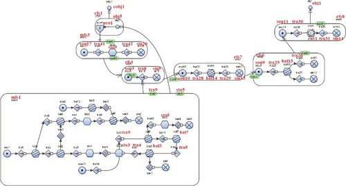
The MFM model related with the isolating ruptured SG operation is shown in . The isolation of ruptured SG is represented by the control flow structure cfs5 and the control function pco5. In this case, the ‘low volume’ in sto6 (as a state modifier) is the goal of the operation. The control function pco5 is evaluated based on the level of sto6. Based on the causal reasoning of MFM, in order to make the low (no) volume in sto6, the transport function tra16 should be in low (no) transport. Therefore, the pco5 is actuated to change the state of tra16 from normal (high) flow to low (no) flow. The objective of the action (cobj5) is to prevent the flow of energy to sto6, tra17, and sto7. By using influence propagation, the explanation sentences for the isolate ruptured SG are shown in . It can be seen that the components influenced by the isolating ruptured SG operation are the turbine, MSIV, reactor coolant pump (RCP), and condenser.
Figure 8. The MFM model of isolate ruptured SG operation.
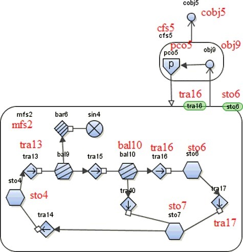
Table 7. Explanantion sentences for the isolate ruptured SG operation
Related with the future plant behavior, this information also can be derived from regarding the state change of the components because of the operation and algorithm described in Section 3.2. The information is provided in . Compared with reactor trip operation, there is no specific technical term to express the future plant behavior. All explanation sentences for the realizing components are presented to operators.
Table 8. Future plant behavior after isolation of ruptured SG operation
It can be concluded from the above discussion that MFM can model the counter actions (automatic operation and human actions) of an EOP of an accident in a nuclear power plant. In addition, by implementing the influence propagation, the influenced function primitives can be investigated and then, the components influenced and the future plant behavior can be derived by using the realization relations.
5. Conclusions
This paper deals with the implementation of MFM for modeling the automatic system and human actions on an EOP. The control functions are used to model the automatic operation and human action on each step of the procedure. The control functions are applied to the SGTR accident of a PWR plant. By modeling the human action on the EOP, the necessary information (explanation sentences) such as the components influenced and future plant behavior because of the automatic operation and human actions can be generated and gathered. The information is very important for operators and helps them understand and take the actions of the procedure step.
Future works are to develop methods on how to present the additional information taken from the explanation sentences on the CBP user interface. The presentation of the information will consider the standards of CBP user interface design and human factor engineering. Moreover, the proposed CBP equipped with the functional information display feature (components influenced and future plant behavior) should be assessed by conducting some experiments in order to measure the usability of the CBP and the utilization of the information for reducing human errors.
Acknowledgments
This study was supported by the scholarship Program for Research and Innovation in Science and Technologies (RISET-Pro), Ministry of Research, Technology and Higher Education of Indonesia [grant number 8245-ID]. In addition, a part of the results of this study was obtained by the support of the Japan Society for the Promotion of Science (JSPS) [KAKENHI grant number 16H03136].
Disclosure statement
No potential conflict of interest was reported by the authors.
| Nomenclature | ||
| CBP | = | Computer-based procedure |
| CVCS | = | Chemical Volume Control System |
| ECCS | = | Emergency core cooling system |
| EOP | = | Emergency operating procedure |
| MFM | = | Multilevel flow modeling |
| MSIV | = | Main steam isolation valve |
| PBP | = | Paper-based procedure |
| PORV | = | Power Operated Relief Valve |
| PWR | = | Pressurized water reactor |
| PZR | = | Pressurizer |
| RCP | = | Reactor coolant pump |
| RCS | = | Reactor coolant system |
| SG | = | Steam generator |
| SGTR | = | Steam generator tube rupture |
Additional information
Funding
Related Research Data
References
- O'Hara J, Higgins J, Kramer J. Advanced information systems design: technical basis and human factors review guidance. Washington (DC): U.S. Nuclear Regulatory Commission; 2000. ( NUREG/CR-6633:2000).
- Askwall S. Computer supported reading vs reading text on paper: a comparison of two reading situations. Int J Man Mach Stud. 1985;22(4):425–439.
- Noyes JM, Garland KJ. Computer vs paper-based tasks: are they equivalent? Ergonomics. 2008;51(9):1352–1375.
- Lee YL, Hwang SL, Wang MY. Reducing cognitive workload of a computer-based procedure system. Int J Hum Comput Stud. 2005;63(6):587–606.
- O'Hara J, Higgins J, Stibler W, et al. Computer-based procedure systems: technical basis and human factors review guidance. Washington (DC): U.S. Nuclear Regulatory Commission; 2000. ( NUREG/CR-6634:2000).
- Marsden P, Green M. Optimising procedures in manufacturing systems. Int J Ind Ergonom. 1996;17(1):43–51.
- Rankin W, Hibit R, Allen J, et al. Development and evaluation of the Maintenance Error Decision Aid (MEDA) process. Int J Ind Ergonom. 2000;26(2):261–276.
- Le Blanc K, Oxstrand J, Waicosky T. Requirements for computer based-procedures for nuclear power plant field operators: results from a qualitative study. Vienna: International Atomic Energy Agency (IAEA); 2012. ( Report; no. IAEA-CN-194).
- Lind M. Means and ends of control. In: Proceedings of IEEE International Conference of System Man and Cybernetics; 2004 Oct 10–13; The Hague, Holland, IEEE, 2004. p. 833–840.
- Fujii H, Gofuku A, Ago T. Operation support in anomalous plant conditions using PKY knowledge. In: Proceedings of SICE Annual Conference; 2008 Aug 20–22; Tokyo, Japan, IEEE, 2008. p. 293–296.
- Hollnagel E, Woods D, Leveson N. Resilience engineering: concepts and precepts. Aldershot: Ashgate; 2006. Epilogue, Resilience engineering precepts; p. 347–358.
- Suryono TJ, Gofuku A. The desirable features of computer based emergency operating procedure for nuclear power operation. IFAC-PapersOnLine. 2016;49(19):403–407.
- Lind M. Modeling goals and functions of complex plant. Appl Artif Intell Int J. 1994;8(2):259–283.
- Lind M. Control functions in MFM: basic principles. Nucl Saf Simul. 2011;2(2):132–129.
- Lind M. An introduction to multilevel flow modeling. Nucl Saf Simul. 2011;2(1):22–32.
- Zhou Y, Yoshikawa H, Wu W, et al. Modeling goals and functions of micro gas turbine system by multilevel flow models. Inf Media Tech. 2006;1:963–972.
- Gofuku A, Koide S, Shimada N. Fault tree analysis and failure mode effects analysis based on multi-level flow modeling and causality estimation. In: Proceeding of SICE–ICASE International Joint Conference; 2006 Oct 18–21; Busan, Korea, IEEE, 2006. p. 497–500.
- Lind M, Yoshikawa H, Jørgensen SB, et al. Multilevel flow modeling of Monju nuclear power plant. Nucl Saf Simul. 2011;2(3):274–284.
- Larsson JE. Knowledge-based methods for control systems [dissertation]. Lund: Lund Institute of Technology; 1992.
- Gofuku A. Multi-level flow modeling and its applications. Nucl Saf Simul. 2015;5(4):305–309.
- Larsson J. Diagnostic reasoning based on means–end models: experiences and future prospects. Knowledge-Based Syst. 2002;15(1–2):103–110.
- Petersen J. Causal reasoning based on MFM. In: Proceedings of Conference on Cognitive System Engineering in Process Control (CSEPC); 2000 Nov 22-25; Taejon, Korea. p. 36–43.
- Gofuku A, Sato T. Development of a dynamic operation permission agent for preventing commission errors of operators. In: Proceedings of Second International Conference on Innovative Computing, Information and Control; 2007 Sept 5–7; Kumamoto, Japan: IEEE, 2007,p.108
- Gofuku A, Sato T. Dynamic operation permission system for oil refinery plants. In: International Conference of Networking, Sensing and Control; 2009 Mar 26–29; Okayama, Japan, IEEE, 2009. p. 746–751.
- Lind M, Zhang X. Functional modelling for fault diagnosis and its applications for NPP. Nucl Eng Technol. 2014;46(6):753–772.
- Gofuku A, Tanaka Y. Display of diagnostic information from multiple viewpoints in anomalous situation of complex plants. In: Proceedings of IEEE International Conference on Systems, Man, and Cybernetics (IEEE SMC '99); 1999 Oct 12 -15; Tokyo, Japan. IEEE, 1999; p. 642–647.
- Zhang X, Lind M, Ravn O. Consequence reasoning in multilevel flow modelling. IFAC Proc Vol. 2013;46(15):187–194.
- Lee S, Kim K, Eun Y. Analyses of SGTR accident with Mihama unit experience. J Korean Nucl Soc. 1994;26(1):41–53.
- Kondo S. Lessons learned for PSA from the SGTR incident at Mihama, unit 2, in 1991. Reliab Eng Syst Saf. 1994;45(1–2):57–65.
- Gofuku A, Inoue T, Sugihara T. A technique to generate plausible counter-operation for an emergency situation based on a model expressing functions of components. J Nucl Sci Technol. 2017;54:578–588.
- Dutton L, Smedley C, Handy J, et al. Realistic methods for calculating the release of radioactivity following steam generator tube rupture faults: a consensus document. Luxembourg: European Comission; 1994. ( Final Report; EUR 15615 EN).