 ?Mathematical formulae have been encoded as MathML and are displayed in this HTML version using MathJax in order to improve their display. Uncheck the box to turn MathJax off. This feature requires Javascript. Click on a formula to zoom.
ABSTRACT
In order to achieve highly accurate resonance calculations with short computation time , a new ultra-fine-group resonance calculation method is developed. The ultra-fine-group method has a limitation in practical design applications of large and complicated geometries in fuel assembly level due to its long computation time. Therefore, we developed an enhanced one-dimensional (1D) cylindrical pin-cell model to achieve both high calculation accuracy and short computation time. In the enhanced 1D cylindrical pin-cell modeling, moderator radius is adjusted to preserve each fuel pellet's Dancoff factor obtained in the exact 2D fuel lattice arrangement. We call this model the ‘equivalent Dancoff-factor’ cell model. This model can accurately consider heterogeneity effects in PWR fuel assemblies and can represent effective cross sections obtained by the ultra-fine-group calculations in the complicated 2D square lattice arrangements. The present method is implemented with Mitsubishi Heavy Industries, Ltd. lattice physics code GALAXY. From the comparisons of neutron multiplication factors and pin power distributions between GALAXY and a continuous-energy Monte Carlo code, applicability of the present method to lattice physics calculations is confirmed. Application of GALAXY with the present method achieves high accuracy with short computation time in normal operations and accident conditions including low moderator density conditions.
1. Introduction
MHI has developed PWR nuclear design code system GALAXY/COSMO-S [Citation1–5]. The GALAXY code [Citation1,Citation2] is a lattice physics code to generate nuclear constants used in the core simulator COSMO-S [Citation3]. After TEPCO's Fukushima Daiichi accident in Japan, a new regulatory standard has been established by the nuclear regulation authority and has been applied to the existing nuclear power plants. For the application of new regulations, it is required to consider design extended conditions (DEC) which have not been covered explicitly by the former safety licensing analyses. In the conventional PWR core design calculation, calculations are usually performed at hot-full-power (HFP) or hot-zero-power (HZP) conditions. In those conditions, the moderator density is approximately 0.7 g/cm3. However, in the DEC such as anticipated transient without scram, the moderator density is varied between around 0.4 and 1.0 g/cm3. Therefore, in order to consider core analysis in further extreme conditions in terms of moderator density, GALAXY has been improved to apply wider moderator range (0–1.0 g/cm3) analysis. In the conventional equivalence theory, a simple 1/E spectrum is assumed in scattering source approximation, and the multi-group cross-section library is prepared in normal operation conditions. The approximation may be valid in normal operation conditions, but may not be sufficient in low moderator density conditions. Another drawback of the conventional equivalence theory is that the resonance interference effects among multiple resonance nuclides cannot be taken into account.
The most straightforward approach to achieve stable and high accuracy in resonance calculations is to apply an ultra-fine-group method instead of the conventional equivalence theory. The ultra-fine-group method provides accurate effective cross sections. It can explicitly treat neutron spectrums for low moderator density conditions and resonance interference effects among multiple resonance nuclides. In the ultra-fine-group method, ultra-fine-group slowing-down equation is solved in heterogeneous geometry to obtain neutron spectra. The ultra-fine-group method can easily treat flexible geometries, for example, intra-pellet multi-ring division and complicated fuel lattice arrangement including multi-type fuel and non-fuel cells. However, the ultra-fine-group method has a limitation in practical design applications in such complicated geometries due to its long computation time. In the earlier lattice physics codes using ultra-fine-group method, resonance calculations are usually carried out in pin-cell geometries. When two-dimensional (2D) square pin cell is applied, the computation time is still long, which takes over an hour, and it is unsuitable for practical design applications [Citation6]. In order to reduce the computation time for practical design applications, some preparation procedures such as collision probability pre-tabulation [Citation6], etc. are required before resonance calculations. The 2D square pin-cell lattice modeling with collision probability pre-tabulation is used in the AEGIS code [Citation6]. On the other hand, the 1D cylindrical pin-cell model is widely used as a traditional geometry modeling of the ultra-fine-group method, e.g. in the PEACO routine of SRAC [Citation7] and the CENTRM module of SCALE [Citation8]. In many lattice physics codes using 1D cylindrical cell model, the moderator radius is set to preserve the moderator volume of 2D square lattice. We call it the ‘equivalent volume’ cell model (EV model). In the EV modeling, Vm/Vf is equivalent to that of 2D square lattice. It can significantly reduce the computation time to a few seconds [Citation6], since the collision probability of 1D cylindrical pin cell can be rapidly calculated. However, the 1D cell approximation decreases calculation accuracy. Moreover, the pin-cell model cannot take account of heterogeneity in fuel assemblies, such as adjacent water rods, water gaps, and reflectors effect, regardless of 2D or 1D pin-cell modeling. These heterogeneity effects in fuel lattice configurations are remarkable in thermal-neutron spectrum conditions rather than in fast-neuron spectrum conditions such as very low moderator density conditions.
In order to solve the above issues of the earlier ultra-fine-group method, we developed a new fine-energy-group method. The basic concepts of this new method are summarized as follows:
| (1) | Short computation time within a few seconds; | ||||
| (2) | No more pre-tabulation except for the ultra-fine-group cross-section library; and | ||||
| (3) | Consideration of heterogeneity of complicated lattice arrangement in fuel assembly level. | ||||
On the basis of the above concepts, all fuel cells in a fuel assembly are directly modeled by using a simple 1D cylindrical pin-cell model in order to satisfy the above concepts (Equation1(1)
(1) ) and (Equation2
(2)
(2) ). For the solution of the concept (Equation3
(3)
(3) ), moderator radius of the 1D cylindrical pin cell is optimized to represent the Dancoff factor, which is obtained by using the enhanced neutron current method (ENCM) [Citation9,Citation10] so as to consider 2D square lattice effects and heterogeneity in a fuel assembly. The optimized moderator radius of the 1D cylindrical pin cell is numerically calculated with iteration. As an approach to reduce the resonance calculation time in practical design applications in the earlier study [Citation11], the relationship between the Dancoff factor and the microscopic multi-group cross section obtained from the ultra-fine-group resonance calculation in the 2D square cell is pre-tabulated and the microscopic multi-group cross section is interpolated from the Dancoff factor in a lattice physics code. In the present method, such pre-tabulation procedures are not necessary since the simple 1D cylindrical pin-cell model achieves short computation time and can consider 2D square lattice effects in the heterogeneous ultra-fine-group resonance calculation. Owing to the needlessness of pre-tabulation except the ultra-fine-group cross-section library, the resonance calculation process is simple.
The contents of each section in the present paper are summarized as follows:
Section 2: The new ultra-fine-group method is proposed. An overview and the calculation procedure of the new method are described.
Section 3: The new method is verified for 2D square UO2 MOX pin-cell and multi-cell lattices in various moderator densities.
Section 4: As a validation of the new method, the Monte Carlo benchmark is carried out for infinite neutron multiplication factors and fission rate distributions in typical PWR UO2/Gd/MOX assemblies.
Section 5: A conclusion of the present study is summarized.
2. Theory
2.1. Overview
2.1.1. Equivalence theory
The underlying theoretical background of the present method is described in this section. The actual calculation procedure is shown in Section 2.2.
The neutron slowing-down equation for heterogeneous system is written as(1)
(1)
The neutron source is(2)
(2)
The macroscopic scattering cross section is given by(3)
(3)
The following assumptions are used for further derivation based on the equivalence theory:
| (i) | Two-region problem consisting of fuel and moderator regions is applied to the neutron slowing-down equation for heterogeneous system. | ||||
| (ii) | The 1/E spectrum is assumed in the slowing-down source calculations. | ||||
| (iii) | The scattering cross sections for the fuel and moderator regions are assumed to be constant in the slowing-down source calculations. They are assumed to be equivalent to the potential cross sections. | ||||
| (iv) | The fuel and moderator regions correspond to the typical resonance and non-resonance material regions, respectively. The scattering and total cross sections in the moderator region are equal. | ||||
| (v) | Anisotropic and inelastic scatterings are negligible. | ||||
| (vi) | Up-scattering is not considered. | ||||
| (vii) | Rational approximation is used for collision probability. | ||||
By using the above assumption (i), EquationEquation (1)(1)
(1) is simplified as the slowing-down equation for two-region heterogeneous system consisting of fuel and moderator [Citation12]:
(4)
(4)
Assumption (ii) is expressed as (5)
(5)
With assumptions (iii) and (iv), the scattering cross sections of the fuel and moderator regions are rewritten as (6)
(6)
With assumptions (v) and (vi), the slowing-down source is rewritten as(7)
(7) where
(8)
(8)
By substituting EquationEquations (5)(5)
(5) and (Equation6
(6)
(6) ) into EquationEquation (7)
(7)
(7) , the slowing-down source can be derived as
(9)
(9)
By substituting the following reciprocity theorem and probability constraint into EquationEquation (4)(4)
(4) ,
(10)
(10)
(11)
(11) The neutron flux in the fuel region is formulated as follows:
(12)
(12)
With assumption (vii), the fuel-to-fuel first-flight collision probability is expressed by Wigner's one-term rational approximation: (13)
(13)
EquationEquation (13)(13)
(13) denotes the fuel-to-fuel first-flight collision probability in isolated system, i.e. a single isolated fuel lump in an infinite moderator medium. By substituting EquationEquation (13)
(13)
(13) into EquationEquation (12)
(12)
(12) , we obtain
(14)
(14)
The escape cross section is defined as an inverse of the mean chord length in the fuel region. For a cylindrical fuel pellet, the escape cross section is the inverse of pellet diameter: (15)
(15)
In the actual fuel assembly, multiple fuel rods are assembled with lattice arrangement, and the fuel-to-fuel first-flight collision probability becomes effectively larger than that in the isolated system due to the effect of neighboring fuel rods. The physical property of the above phenomenon is considered as the lattice effects in general resonance self-shielding theory. By using the Dancoff factor D, the fuel-to-fuel first-flight collision probability in the lattice geometry is obtained as(16)
(16)
The escape cross section in the fuel region Σfe is corrected by the Dancoff factor.
By substituting EquationEquation (16)(16)
(16) into EquationEquation (12)
(12)
(12) , the neutron flux is formulated as
(17)
(17)
As shown in EquationEquation (17)(17)
(17) , the ultra-fine-group neutron spectra in the fuel region are expressed as a function of the Dancoff factor. The Dancoff factor can consider complicated lattice configuration effects such as lattice geometries and fuel rod arrangements by using the ENCM. By using EquationEquation (17)
(17)
(17) , the total reaction rate in the fuel region is written as
(18)
(18)
When Σft(E) is very large (i.e. Σft(E) → ∞), EquationEquation (18)(18)
(18) can be simplified as
(19)
(19)
EquationEquation (19)(19)
(19) is averaged by lethargy and we then obtain
(20)
(20)
In the ENCM, a one-group transport equation is solved by the method of characteristics (MOC) [Citation13] in actual geometries such as fuel assemblies, based on fixed source problem. The total cross section in the fuel region is set to a large value (e.g. 105 cm−1), and the total cross section in non-fuel regions and neutron source in all regions are set to the macroscopic potential cross section for these regions.
The total reaction rate can be numerically evaluated and EquationEquation (20)(20)
(20) can then be rewritten as
(21)
(21)
The product of the Dancoff factor and the escape cross section can be written as(22)
(22)
By using the intermediate resonance (IR) approximation [Citation14], the macroscopic potential cross section is defined as (23)
(23)
EquationEquation (22)(22)
(22) can be rewritten as [Citation9]
(24)
(24)
For a fuel rod in a lattice geometry, the Dancoff factor using the ENCM and IR approximation is defined as(25)
(25)
2.1.2. New method based on ultra-fine-group resonance calculation
EquationEquation (17)(17)
(17) is not adequate for the accurate ultra-fine-group calculations since assumptions (i) through (vii) are used. We eliminated the assumptions and improved the calculation accuracy. In order to remove assumptions (i) through (iv) and (vii), the following slowing-down equation for the 1D cylindrical cell model is used instead of EquationEquation (17)
(17)
(17) :
(26)
(26)
(27)
(27) where
is an adjusted moderator volume to represent the Dancoff factor obtained in the actual lattice configurations and fuel rod arrangements by using EquationEquation (25)
(25)
(25) . In the actual calculation procedure, the moderator radius
of the 1D cylindrical cell model is numerically optimized to represent the Dancoff factor for each fuel rod with iterative calculation. The calculation procedure of
is described in Section 2.2.2. EquationEquations (26)
(26)
(26) and (Equation27
(27)
(27) ) are derived from the assumptions that the heterogeneity effects in the fuel lattice configurations can be treated by the adjustment of moderator radius in 1D cylindrical cell model. We call this model the ‘Equivalent Dancoff-factor’ model (ED model). EquationEquation (26)
(26)
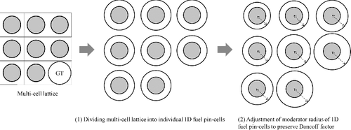
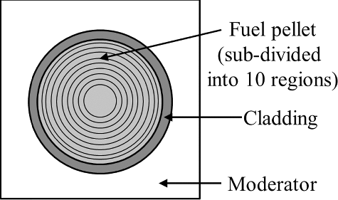
(26) is solved by the 1D collision probability method, and the computation time of the ultra-fine-group method is very short. It can be easily extended and applied to the intra-pellet multi-ring model. It is necessary for Gd depletion calculations in the fuel pellet and intra-pellet power distribution calculations. A concept of the present method is illustrated in .
We will not remove assumptions (v) and (vi). For assumption (v), the anisotropic scattering has no significant impact on effective resonance cross sections [Citation6]. In the resolved resonance range, elastic scattering is dominant. Thus, assumption (v) is applicable. In this paper, discussion for the selection of scattering model, i.e. the asymptotic model or the exact resonance scattering model [Citation15,Citation16], is out of scope. We selected the asymptotic model and did not consider up-scatterings. Thus, assumption (vi) is applied. The neutron source is expressed as(28)
(28)
In the verification and validation (V&V) discussed in Sections 3 and 4, the reference calculations by Monte Carlo code apply the asymptotic scattering model.
2.1.3. Reaction rate preservation using the SPH method
By using the ultra-fine-group neutron spectra from the solution of EquationEquation (26)(26)
(26) , the ultra-fine-group microscopic cross sections σkx(E) are collapsed to the multi-group microscopic cross sections as
(29)
(29)
By using the multi-group microscopic cross sections, the multi-group macroscopic cross sections are expressed as (30)
(30)
The multi-group reaction rate cannot represent the energy-integrated reaction rate by using the ultra-fine-group calculation results given by EquationEquation (26)(26)
(26) :
(31)
(31)
(32)
(32) Φig denotes the multi-group neutron flux and it is obtained from the multi-group transport calculations using collision probability method in the 1D cylindrical pin cell with the multi-group macroscopic cross sections Σix, g. Neutron flux level is normalized as
(33)
(33)
In the right side of EquationEquation (31)(31)
(31) , the ultra-fine-group macroscopic cross sections are defined as
(34)
(34)
In order to preserve the ultra-fine-group reaction rate, the super-homogenization (SPH) method is used [Citation6,Citation17]. The SPH factor after the n-time iteration is defined as(35)
(35)
The SPH factor can be determined to satisfy EquationEquation (36)(36)
(36) with iteration:
(36)
(36)
After the n-time iteration, the multi-group microscopic cross sections obtained by the ultra-fine-group method are corrected by the SPH factor: (37)
(37)
The multi-group macroscopic cross sections are also corrected as (38)
(38)
By substituting the corrected multi-group macroscopic cross sections instead of Σix, g in EquationEquation (32)
(32)
(32) , EquationEquation (32)
(32)
(32) is rewritten as
(39)
(39) where
and
denote the collision probability and neutron source using
, respectively.
The multi-group neutron flux Φi, ng is recalculated by EquationEquation (39)(39)
(39) . The calculation process based on Equation (Equation39
(39)
(39) ) is iterated until the SPH factor converges. After the SPH factor convergence, the transport calculations using
are carried out by MOC in the exact 2D square lattice configurations.
2.2. Calculation procedure
2.2.1. ‘Equivalent Dancoff-factor’ model based on ultra-fine-group resonance treatment
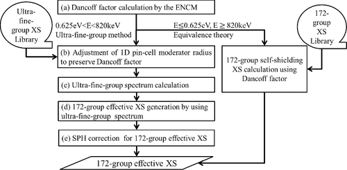
The present ultra-fine-group method is implemented with the GALAXY code. In the conventional resonance calculation of GALAXY for nuclear design applications, the multi-group effective cross sections are generated by the spatially dependent gray resonance method [Citation2] based on the equivalence theory. The cross-section library applies 172-group XMAS structure [Citation18], which is based on ENDF/B-VII.0 [Citation19]. It was prepared by the NJOY code [Citation20] in the same manner as widely used lattice physics codes. The ultra-fine-group (120,000 groups) cross sections between 20 MeV and 10−5 eV are added to the cross-section library of GALAXY based on ENDF/B-VII.0. The energy group structure of 120,000 groups is shown in , which is based on the structure of SLAROM-UF [Citation21] code except for the fast and thermal energy ranges. The collapsed cross sections by using the ultra-fine-group method are applied to the energy range from 820 keV to 0.625 eV. The 172-group XMAS structure is fine enough for the energy range lower than 0.625 eV. For example, it can treat large resonance peak of 239Pu at 0.3 eV without considering the self-shielding effects. In the energy range that is less than 0.625 eV or over 820 keV, the conventional equivalence theory is applied. The effective cross sections for non-fuel region are also generated by the equivalence theory. The calculation flow of the heterogeneous ultra-fine-group spectra and the 172-group cross sections is briefly summarized in . Each calculation step is described as follows:
| (a) | The Dancoff factor of each fuel rod is evaluated in calculation geometry (e.g. fuel assembly) by the ENCM. | ||||
| (b) | The moderator radius of each fuel cell is numerically adjusted to represent the Dancoff factor obtained in step (a) with iteration. The moderator radius adjustment process is described in Section 2.2.2. It was confirmed that the iteration calculation converges within several iterations. A relative iteration criterion of radius is 10−4, in which the impact of reactivity is about 1 pcm (10−3%dk/k), corresponding to the criterion of neutron multiplication factor in the transport calculation of GALAXY. | ||||
| (c) | The heterogeneous ultra-fine-group spectrum calculations by using EquationEquation (26) | ||||
| (d) | In the energy range from 0.625 eV to 820 keV, the ultra-fine-group cross sections are collapsed to the 172-group cross sections by using EquationEquation (29) | ||||
| (e) | Based on Section 2.1.3, the SPH correction is applied to the 172-group effective cross sections obtained in step (d) to represent the ultra-fine-group-based reaction rate. The SPH factors are obtained with iteration. A relative iteration criterion of the SPH factor is 10−4, in which the impact of reactivity is about 1 pcm. | ||||
Table 1. Ultra-fine-group energy structure
After the resonance calculations, the transport calculations applying multi-group cross sections are carried out by MOC in the exact 2D square lattice configurations.
2.2.2. Numerical calculation of moderator radius in the 1D cylindrical cell modeling
As mentioned in Section 2.1.2, the Dancoff factor in fuel region of the 1D cylindrical cell is given by(40)
(40)
EquationEquation (40)(40)
(40) is a function of
since φ∞ is the neutron flux in the 1D cylindrical cell of the moderator radius
. The neutron flux φ∞ in EquationEquation (39)
(39)
(39) is calculated by using the 1D collision probability method, based on the one-group fixed source problem. The total cross section in the fuel region is set to a large macroscopic cross section Σf∞ (e.g. 105 cm−1), and the total cross section in non-fuel regions and the neutron source in all regions are set to the macroscopic potential cross section for these regions.
In order to represent the Dancoff factor D obtained by the ENCM in the exact 2D lattice configuration, the moderator radius needs to be satisfied with
(41)
(41)
EquationEquation (41)(41)
(41) is rewritten as
(42)
(42)
The moderator radius is obtained by the numerical solution of EquationEquation (42)
(42)
(42) .
3. Verification
3.1. Unit pin-cell lattice
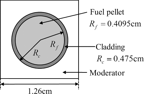
In this section, the present method for resonance treatment is verified by using the unit pin-cell geometries. UO2 (4.8 wt% 235 U) and MOX (7.2 wt% Pu fissile contents) pin-cell calculations are carried out in 0.71 and 0.10 g/cm3 moderator densities, which correspond to the normal operation conditions at HFP and the accident conditions, respectively. The specifications of the pin cell are shown in and the geometrical configuration is shown in .
Table 2. Specifications of the pin-cell model
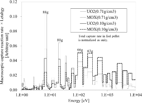
The ultra-fine-group macroscopic reaction rates calculated by the direct 2D square cell model, 1D cylindrical ED model, and 1D cylindrical EV model are shown in for important resonance energy ranges. The important energy ranges are selected from the magnitude of macroscopic capture reaction rate as shown in . The selected energy ranges are summarized in . The results of direct 2D square lattice model are the reference and are calculated by the continuous-energy Monte Carlo code MVP [Citation22]. The Dancoff factor and the moderator radius for each model in the above conditions are summarized in . The Dancoff factor is common in both UO2 and MOX fuel cases due to the same specifications except for the fuel pellet compositions. The Dancoff factor in low moderator density is smaller than that in high moderator density. Then, the radius of ED model in low moderator density is larger than that in high moderator density. The EV model radius is independent of moderator density, which is larger than the ED radius of both moderator density cases. As shown in , the present method with the ED model can accurately predict the reaction rate of 2D square cell model compared with the EV model, especially for the low neutron energy ranges (i.e. 80th and 88th groups). By using the ED model, the reaction rate accuracy in the low energy ranges can be improved significantly. In the high energy ranges (i.e. 63rd and 66th groups), the reaction rate difference between the EV and ED models is small.
Figure 4. Comparison of ultra-fine-group macroscopic absorption rates between 2D square and 1D cylindrical models for UO2 fuel (moderator density: 0.71 g/cm3).
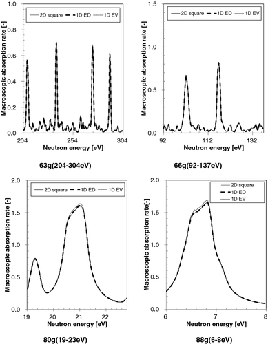
Figure 5. Comparison of ultra-fine-group macroscopic absorption rates between 2D square and 1D cylindrical models for UO2 fuel (moderator density: 0.10 g/cm3).
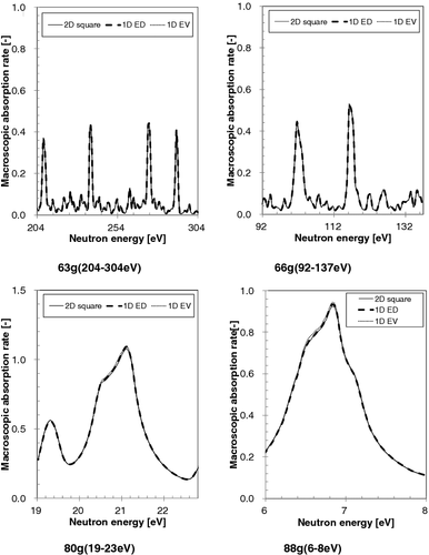
Figure 6. Comparison of ultra-fine-group macroscopic absorption rates between 2D square and 1D cylindrical models for MOX fuel (moderator density: 0.71 g/cm3).
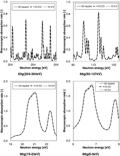
Figure 7. Comparison of ultra-fine-group macroscopic absorption rates between 2D square and 1D cylindrical models for MOX fuel (moderator density: 0.10 g/cm3).
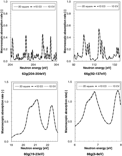
Table 3. Important resonance-energy ranges in 172-group XMAS structure
Table 4. Dancoff factor and moderator radius of the equivalent Dancoff-factor model in UO2/MOX fuel
The multi-group macroscopic absorption cross sections in the fuel region obtained by GALAXY with the ED model and the EV model are compared with those by the MVP code with the exact 2D square model in . The MVP code employs the same ENDF/B-VII.0 library as GALAXY. The statistical error (1σ) of MVP results is less than 0.1%. In this paper, the number of neutron samplings for all MVP calculations is set to 100 million histories. The present method with the ED model can accurately represent the multi-group macroscopic cross sections of 2D square cell model, in comparison with the EV model. Significant trends are not observed as a function of the fuel type and moderator density.
Table 5. Comparison of multi-group macroscopic absorption cross sections in fuel pellet of unit pin cell
3.2. Unit pin-cell lattice with intra-pellet multi-ring division
The present method can be easily applied to the intra-pellet multi-ring division. In the multi-ring modeling, the reaction rate of the outermost ring in fuel pellet is dominant in all intra-pellet rings, which is very important for calculation accuracy. Therefore, the multi-group macroscopic absorption cross sections in the peripheral ring of fuel pellet obtained by GALAXY with the ED model and the EV model are compared with those by the MVP with 2D square model. In this verification, the fuel pellet of the unit pin cell used in Section 3.1 is divided into 10 rings with equal volume, as illustrated in . UO2 and MOX unit pin-cell calculations with normal operation condition at HFP are performed.
The calculation results are summarized in . The statistical error of MVP results is less than 0.3%. As well as the unit pin-cell lattice without radial fuel division, the ED model can accurately predict the multi-group macroscopic cross sections of the 2D square MVP results rather than the EV model.
Table 6. Comparison of multi-group macroscopic absorption cross sections in peripheral region of fuel pellet
3.3. Multi-cell lattice
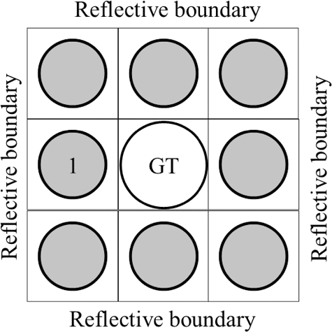
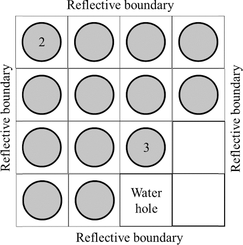
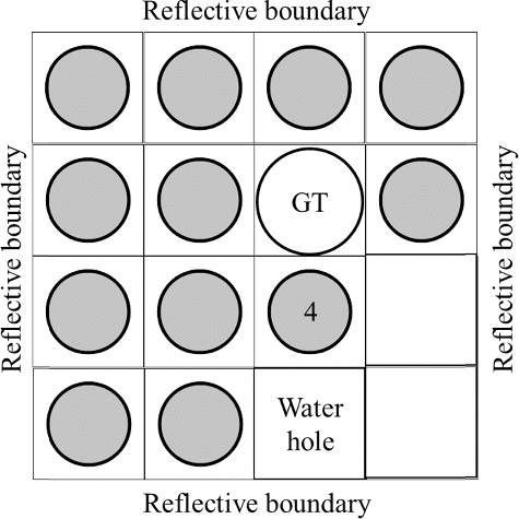
The present method with the ED model can consider heterogeneity effects from adjacent non-fuel cells, such as guide tube (GT) cells, instrumental thimble (IT) cells, water holes and water gaps between assemblies, etc. Verifications of the present method are carried out by using the 3 × 3 cell lattice including a GT cell, the 4 × 4 cell lattice including three water holes, and the 4 × 4 cell lattice including a GT cell and three water holes. The 3 × 3 and 4 × 4 cell lattices are illustrated in , respectively. The basic calculation conditions such as fuel composition, cell pitch, fuel rod geometry, and temperature are the same as those applied to the unit pin-cell calculations in Section 3.1.
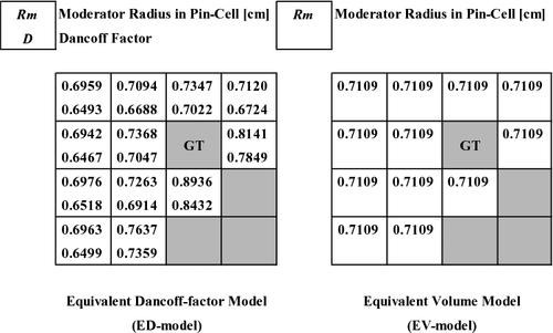
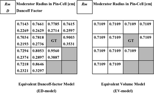
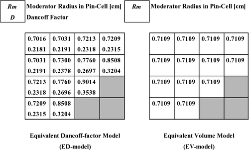
An objective of the verification is to confirm the applicability of the present method to the multi-cell calculations including several non-fuel cells. The Dancoff factor and moderator radius of the ED and EV models are shown in –. As can be seen from these figures, the Dancoff factor and moderator radius in the fuel cells adjacent to GT/water cells become large. In the EV model, the moderator radius is common in all the fuel cells and cannot consider heterogeneity effects caused by the adjacent non-fuel cells. show comparisons of the multi-group macroscopic absorption cross sections between GALAXY and MVP in the numbered fuel pellets in . The statistical error of MVP results is less than 0.3%. The present method with the ED model can represent the MVP results better than the EV model. Especially for the fuel rods adjacent to non-fuel cells in which the EV model has large difference from the MVP results, the ED model is in good agreement with the MVP results. By using the present method, the agreement of the multi-group macroscopic cross sections between the GALAXY and MVP codes has improved in 0.71 and 0.10 g/cm3 moderator density conditions.
Figure 13. Dancoff factor and moderator radius of the ED and EV models in 3 × 3 cell lattice (moderator density: 0.71 g/cm3).
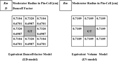
Figure 14. Dancoff factor and moderator radius of the ED and EV models in 3 × 3 cell lattice (moderator density: 0.10 g/cm3).
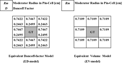
Figure 15. Dancoff factor and moderator radius of the ED and EV models in 4 × 4 cell lattice with water holes (moderator density: 0.71 g/cm3).
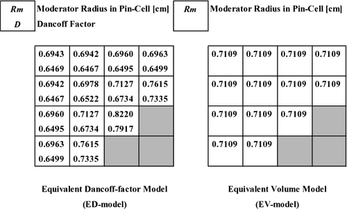
Figure 16. Dancoff factor and moderator radius of the ED and EV models in 4 × 4 cell lattice with water holes (moderator density: 0.10 g/cm3).
4. Validation
4.1. Unit pin-cell lattice
For the validation of applicability of the infinite neutron multiplication factor (k-infinity) obtained by GALAXY in which the present method is used in the extended moderator density range from 0 to 1 g/cm3, the Monte Carlo benchmarks are carried out by using unit pin cells. With the same calculation conditions as Section 3.1, the k-infinity in the unit pin cells is compared between GALAXY and MVP, as shown in . The statistical error of k-infinity given by MVP is less than 10 pcm. In order to cover the extended moderator density conditions including cold zero power and dry-up conditions, the moderator density range is extended to 0–1 g/cm3. By using the present method with the ED model, GALAXY can accurately predict the k-infinity of MVP for the UO2 and MOX fuel cells within 230 pcm in the extended moderator density range. The k-infinity difference from MVP regarding the moderator density condition of MOX fuel cells around 0 g/cm3 is merely larger than other conditions. The k-infinity difference is much smaller than the acceptance criterion in reload startup physics tests for PWRs. The criterion is ±50 ppm critical boron concertation or ±500 pcm reactivity equivalent [Citation23]. In around 0 g/cm3 moderator density conditions, the neuron spectra are located in unresolved resonance range in which inelastic scattering is not negligible. Therefore, exclusion of inelastic scattering effects in the ultra-fine-group calculation may merely increase the k-infinity difference. In a very low moderator density close to 0 g/cm3, the results of the ED model are comparable with the EV model. This is because the heterogeneity effects in fuel assemblies are almost negligible in such fast-neutron spectrum conditions. The difference of ultra-fine-group macroscopic reaction rate between the ED and EV models is small in high-energy resonance ranges, as discussed in Section 3.1. In addition, neutron spectra become hard in moderator density conditions around 0 g/cm3 and the contribution of resonance absorption in low energy range is very small. We confirmed that the present method is applicable to wide moderator density range from 0 to 1 g/cm3. The ED model can accurately consider 2D square lattice configuration effects into the 1D pin-cell modeling.
4.2. Multi-cell lattice
For the validation of heterogeneity effects of GALAXY in which the present method is applied, the Monte Carlo benchmarks are carried out by using multi-cell lattices including non-fuel cells. With the same calculation conditions as Section 3.3, the k-infinity in the multi-cell lattice calculations is compared between GALAXY and MVP. – show the k-infinity difference from MVP in the 3 × 3 and 4 × 4 cells. The statistical error of k-infinity given by MVP is less than 10 pcm. For additional discussion, we added the ‘EA model’ as another 1D cylindrical model used in the ultra-fine-group resonance calculation. The EA model is the 1D cylindrical cell modeling to preserve ‘averaged’ moderator volume of multi-cell lattice including non-fuel cells, which is an easy approach to take account of the influence of non-fuel cells such as GT/IT, water hole, and so on. It is well applied to the assembly-averaged typical pin-cell modeling. An equivalent moderator radius of the EA model is larger than that of the EV model, as shown in . The EV and EA models have large difference from MVP in some conditions. The ED model is in good agreement with MVP, which shows stable accuracy with exceedingly smaller systematic difference in fuel type and moderator density from MVP, in comparison with the EV and EA models. The difference of k-infinity is less than 100 pcm. We confirmed that the ED model can consider heterogeneity effects in multi-cell lattice including non-fuel cells.
Table 7. Comparison of multi-group macroscopic absorption cross sections in fuel rod of 3 × 3 cell
Table 8. Comparison of multi-group macroscopic absorption cross sections in fuel rod of 4 × 4 cell with water holes
Table 9. Comparison of multi-group macroscopic absorption cross sections in fuel rod of 4 × 4 cell with GT cell and water holes
Table 10. Comparison of k-infinity in unit pin cell for various moderator densities
Table 11. Comparison of k-infinity in 3 × 3 cell
Table 12. Comparison of k-infinity in 4 × 4 cell including water holes
Table 13. Comparison of k-infinity in 4 × 4 cell including GT cell and water holes
Table 14. Moderator radius of the ultra-fine-group resonance calculation in multi-cell problems
4.3. Single fuel assembly
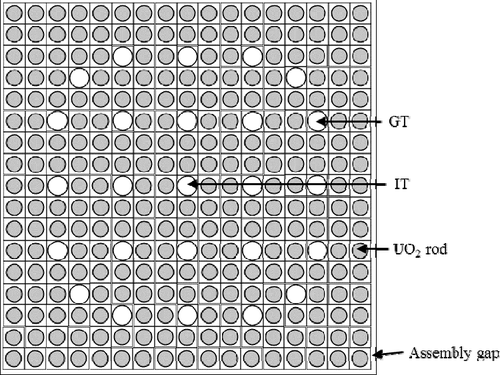
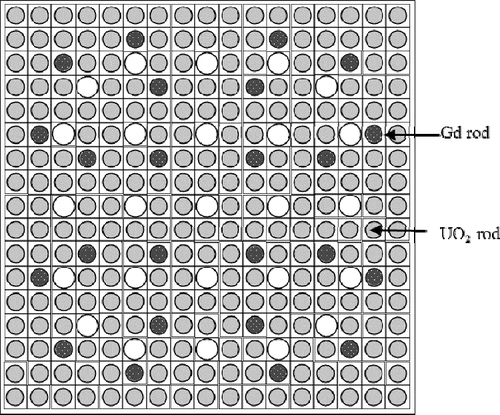
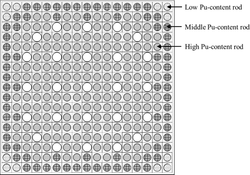
For the validation of GALAXY in which the ultra-fine-group resonance calculation is used, the Monte Carlo benchmarks are carried out for UO2, Gd, and MOX fuel assemblies. The assembly geometries are designed based on typical 17 × 17 UO2, Gd, and MOX fuel assemblies in PWRs. The assembly configurations are illustrated in –. The Gd2O3-bearing fuel pellet in the 17 × 17 Gd fuel assembly is radially subdivided into 10 rings with equal volume splitting. The calculation conditions are normal operation conditions at HFP as shown in .
Table 15. Specifications of assembly model
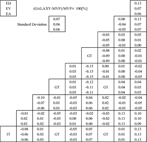
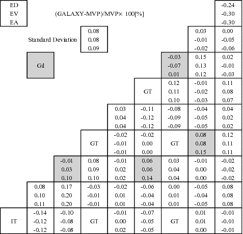
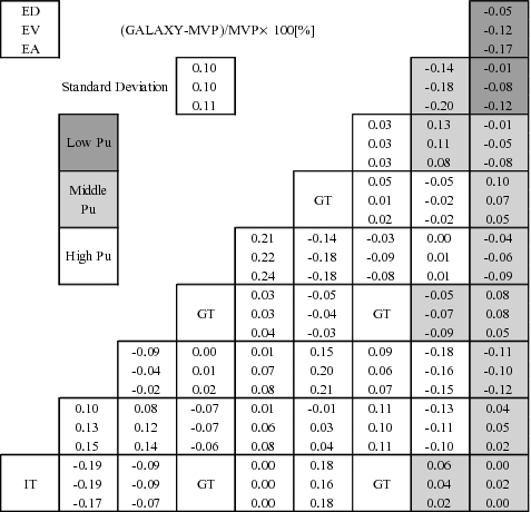
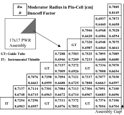
In the benchmarks, k-infinity and fission rate distribution (pin power) within fuel assemblies are compared to the MVP results. The comparisons of k-infinity and pin-power distribution between GALAXY and MVP are shown in and , respectively. The statistical errors of k-infinity and pin power given by MVP are less than 10 pcm and 0.2%, respectively. For the ED, EV, and EA models, the difference of pin-power distribution from MVP is summarized in –. The Dancoff factors and moderator radius of the EV model are shown in . The moderator radii of the EV and EA models are 0.7109 and 0.7435 cm, respectively. The equivalent moderator radius obtained from the Dancoff factors in fuel cells adjacent to GT and IT becomes large. The calculation results of the ED, the EV, and the EA models are compared. From the results of comparison, it is confirmed that the present method with the ED model can well represent the reference results, which resulted in negligibly small systematic difference in fuel types from MVP. The difference of k-infinity is less than 100 pcm. The EA model has large difference in k-infinity from MVP since the moderator radius of 1D pin cell in fuel assemblies is too large. The ED model can reduce maximum pin-power difference from MVP in comparison with the EV and EA models, and there is no systematic difference beyond the MVP statistical error in fuel pin location, as illustrated in –. The relative calculation time of effective cross-section calculations based on the ultra-fine-group resonance method is less than 5% of the total calculation time of GALAXY. The ultra-fine-group resonance calculation time in each fuel pellet is less than a second.
Table 16. Comparison of k-infinity in single fuel assembly at normal operation condition
Table 17. Comparison of pin power in single fuel assembly at normal operation condition
Figure 25. Dancoff factors and moderator radius of the equivalent Dancoff-factor model in PWR assembly at normal operation condition.
With the same fuel assembly specifications as the normal operation condition, the 0.4 and 0.1 g/cm3 moderator density condition calculations are carried out for the typical 17 × 17 UO2, Gd, and MOX fuel assemblies in PWRs. The comparisons of k-infinity and pin-power distribution between GALAXY and MVP are summarized in and , respectively. The statistical errors of k-infinity and pin power given by MVP are less than 10 pcm and 0.2%, respectively. In the low moderator density conditions, the present method with the ED model can accurately reproduce the MVP k-effectives and pin-power distributions in comparison with the EV and EA models. The maximum differences of k-effective and pin-power distribution are less than 200 pcm and 0.7%, respectively. In some cases, the k-effective difference in the low moderator density conditions is merely larger than that in the normal operation conditions. However, the differences are much smaller than the acceptance criterion discussed in Section 4.1.
Table 18. Comparison of k-infinity in single fuel assembly in 0.4 and 0.1 g/cm3 moderator density conditions
Table 19. Comparison of pin power in single fuel assembly in 0.4 and 0.1 g/cm3 moderator density conditions
4.4. Fuel assembly adjacent to baffle reflector
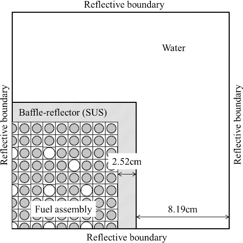
In this section, examples of the application of the new resonance method for a complicated geometry are described. The PWR types of 17 × 17 UO2 and MOX fuel assemblies adjacent to baffle-reflector regions are applied. The configuration of fuel assemblies with baffle-reflector regions is shown in . There are no assembly gaps between the fuel assembly and the baffle reflector. The fuel specifications and fundamental calculation conditions are the same as those applied to the single assembly calculations in Section 4.3.
The Dancoff factors and moderator radius of the EV model are shown in . The moderator radii of the EV and EA models are 0.7109 and 0.7407 cm, respectively. In this case, the EA model does not consider reflector regions. The equivalent moderator radius obtained from the Dancoff factors in fuel cells adjacent to GT, IT, and baffle reflector becomes large. The comparisons of k-infinity and pin-power distribution between GALAXY and MVP are shown in and , respectively. The statistical errors of k-infinity and pin power given by MVP are approximately 10 pcm and 0.2%, respectively. The difference of pin-power distribution is summarized in and . As well as the validation in single assembly calculations, the present method with the ED model is in good agreement with the reference results, which resulted in negligible systematic difference in fuel types and geometry configurations. The difference of k-infinity is less than 100 pcm. The EV model has large difference in k-infinity from MVP since the moderator radius of 1D pin cell close to reflector regions is small. The ED model can reduce maximum pin-power difference from MVP in comparison with the EV and EA models. The relative calculation time of effective cross-section calculations based on the ultra-fine-group resonance method is less than 2% of the total calculation time. The ultra-fine-group resonance calculation time in each fuel pellet is less than a second.
Figure 27. Dancoff factors and moderator radius of the equivalent Dancoff-factor model in PWR assembly adjacent to baffle reflector.
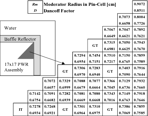
Table 20. Comparison of k-infinity in fuel assembly adjacent to baffle-reflector regions
Table 21. Comparison of pin power in fuel assembly adjacent to baffle-reflector regions
Figure 28. Pin-power comparison between GALAXY and MVP in PWR UO2 assembly adjacent to baffle reflector.
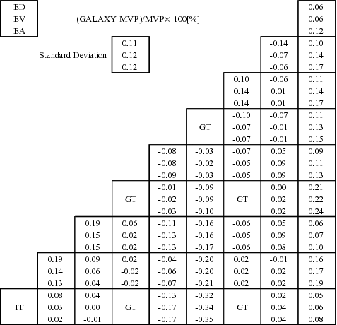
Figure 29. Pin-power comparison between GALAXY and MVP in PWR MOX assembly adjacent to baffle reflector.
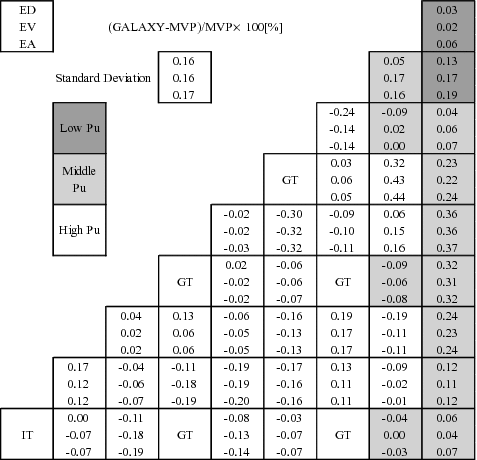
From the V&V results in Sections 4.3 and 4.4, it is confirmed that the ED model is applicable to practical PWR design applications with short computation time.
5. Conclusion
A new ultra-fine-group resonance self-shielding treatment method is developed in the present study. The ultra-fine-group method is implemented into the GALAXY code to achieve highly accurate resonance calculations. The present method divides a fuel assembly into individual 1D cylindrical fuel cell. In each 1D fuel cell, the ultra-fine-group neutron spectrum calculation is carried out. The moderator radius of the 1D fuel cell is adjusted to preserve the Dancoff factor obtained from the exact 2D fuel lattice geometry modeling by using the ENCM. The 1D pin-cell model using the equivalent Dancoff-factor radius adjustment can treat heterogeneity effects of complicated fuel rod arrangements with short computation time. Due to the short computation time, pre-tabulations except the ultra-fine-group cross-section library are not necessary and thus the resonance calculation process is simple. The new features in the present method are summarized as follows:
The Dancoff factor taking account of 2D square lattice effects and heterogeneity in a fuel assembly is obtained by the ENCM.
The 1D cylindrical pin-cell modeling to preserve the Dancoff factor achieves both high accuracy and short computation time.
By comparing the neutronics characteristics obtained by GALAXY and MVP, good agreements between the two codes are obtained in wide moderator density ranges for several PWR fuel specifications. From the V&V results, applicability of the present method to the general lattice physics calculations is confirmed. Application of GALAXY implemented with the present method achieves high accuracy with short computation time in normal operations and accident conditions including wide moderator density ranges. Therefore, it can be efficiently applied to the generation of nuclear constants used in nuclear design and safety analysis of commercial PWRs.
| Nomenclatures | ||
| Ak | = | relative atomic weight of nuclide k to the neutron |
| αk | = | maximum energy loss ratio for nuclide k defined as |
| D | = | Dancoff factor using the ENCM in 2D exact square lattice configuration |
| D1D | = | Dancoff factor in 1D cylindrical cell modeling |
| ΔD | = | Dancoff-factor difference between D and D1D |
| E | = | neutron energy |
| f | = | fuel region |
| fi(E′ → E) | = | energy transmission probability from E' to E in region i |
| g | = | index for energy group (multi-group resolution) |
| k | = | index for nuclide |
| i, j | = | index for region |
| I | = | total reaction rate |
| lf | = | mean chord length of fuel lump |
| λk | = | IR parameter for nuclide k |
| m | = | moderator region |
| μi, ng | = | SPH factor for group g in region i after the nth iteration calculation |
| n | = | the number of iteration |
| Nki | = | number density of nuclide k in region i |
| φi | = | ultra-fine-group neutron flux in region i |
| φ∞ | = | neutron flux obtained from the ENCM using large macroscopic cross section (∼105 cm−1) |
| Φig | = | multi-group neutron flux in region i for energy group g |
| Pj → i | = | collision probability from regions j to i |
| Qi | = | neutron source for region i |
| Rf | = | fuel pellet radius |
| Rc | = | outer radius of fuel rod cladding |
| Rm | = | moderator radius of 1D cylindrical pin cell |
|
| = | adjusted moderator radius of 1D cylindrical pin cell to represent Dancoff factor |
| Σfe | = | escape cross section in fuel region |
| Σip | = | macroscopic potential cross section in region i |
| Σit | = | macroscopic total cross section in region i |
| Σis | = | macroscopic scattering cross section in region i |
| Σix, g | = | macroscopic cross section in region i for energy group g and reaction type x |
|
| = | macroscopic cross section corrected by SPH factor in region i for energy group g and reaction type x after the nth iteration calculation |
| Σ∞ | = | large macroscopic cross section in the case of black limit (i.e. 105 cm−1) |
| σkp | = | microscopic potential cross section for nuclide k |
| σks | = | microscopic scattering cross section for nuclide k |
| σkx | = | microscopic cross section for nuclide k and reaction type x |
| σk, ix, g | = | microscopic cross section for nuclide k, energy group g, and reaction type x in region i |
|
| = | microscopic cross section corrected by SPH factor for nuclide k, energy group g, and reaction type x in region i after the nth iteration calculation |
| Vm/Vf: | = | volume ratio of moderator and fuel region |
| Vi | = | volume for region i |
| x | = | index for reaction type |
| XS: | = | cross section |
Acknowledgments
The authors would like to thank colleagues of Mitsubishi Heavy Industries, Ltd. (MHI) and MHI Nuclear Systems and Solution Engineering Co., Ltd. for their invaluable advice and help. The authors also wish to thank Mr M. Ido for his considerable contributions in the actual development.
Disclosure statement
No potential conflict of interest was reported by the authors.
References
- Yamaji K, Matsumoto H, Kirimura K, et al. Development of a new lattice physics code GALAXY for flexible geometry representation in next generation core analysis system. Trans Am Nucl Soc. 2007;97:573–574. [ CD-ROM].
- Koike H, Yamaji K, Kirimura K, et al. Advanced resonance self-shielding method for gray resonance treatment in lattice physics code GALAXY. J Nucl Sci Technol. 2012;49:725–747.
- Sato D, Tsubota S, Yamaji K, et al. A new robust cross section representation methodology for PWR core simulator. Proceedings of International Conference on physics of Reactors (PHYSOR 2010). 2010 May 9–14. Pittsburgh, PA, USA. [ CD-ROM]
- Kosaka S, Kirimura K, Yamaji K, et al. Development of MHI core analysis code package based on GalaxyCosmo-S. Trans Am Nucl Soc. 2013;109:1348–1350. [ CD-ROM].
- Kirimura K, Yamaji K, Kosaka S, et al. Verification and validation of MHI nuclear design code system GalaxyCosmo-S. Trans Am Nucl Soc. 2013; 109: 1336–1338. [ CD-ROM].
- Sugimura N, Yamamoto A. Resonance treatment based on ultra-fine-group spectrum calculation in the AEGIS code. J Nucl Sci Technol. 2007;44:958–966.
- Ishiguro Y. PEACO-II: A code for calculation of effective cross section in heterogeneous systems. Ibaraki: Japanese Atomic Energy Research Institute (JAERI); 1971. JAERI-M 5527.
- Williams M, Asgari M. Computation of continuous-energy neutron spectra with discrete ordinates transport theory. Nucl Sci Eng. 1995;121:173–201.
- Yamamoto A. Evaluation of background cross section for heterogeneous and complicated geometry by the enhanced neutron current method. J Nucl Sci Technol. 2008;45:1287–1292.
- Sugimura N, Yamamoto A. Evaluation of Dancoff factors in complicated geometry using the method of characteristics. J Nucl Sci Technol. 2006;43:1182–1187.
- Tatsumi M, Ohoka Y, Sugimura N, et al. [Core Analysis of a Commercial PWR with AEGIS/SCOPE2] [CD-ROM]. Proceedings of 2008 Annual Meeting of AESJ;2008 March 26-28. Osaka (Japan). L36 [ in Japanese].
- Stamm'ler RJJ, Abbate MJ. Methods of steady-state reactor physics in nuclear design. London: Academic Press; 1983.
- Askew R. A characteristics formulation of the neutron transport equation in complicated geometries. Winfrith: Atomic Energy Authority; 1972. AEEW-M1108.
- Goldstein R, Cohen E R. Theory of resonance absorption of neutrons. Nucl Sci Eng. 1962;13:132–140.
- Ouisloumen M, Sanchez R. A model for neutron scattering off heavy isotopes that accounts for thermal agitation effects. Nucl Sci Eng. 1990;107:189–200.
- Lee D, Smith K, Rhodes J. The impact of 238 U resonance elastic scattering approximations on thermal reactor Doppler reactivity. Ann Nucl Energ. 2009;36(3):274–280.
- Hebert A. A consistent technique for the pin-by-pin homogenization of a pressurized water reactor assembly. Nucl Sci Eng. 1993;113:227–238.
- Sartori E. Standard energy group structures of cross section libraries for reactor shielding, reactor cell and fusion neutronics applications: VITAMIN-J, ECCO-33, ECCO-2000 and XMAS, JEF/DOC-315, Revision 3. Gif-sur-Yvette: NEA Data Bank; 1990.
- Chadwick MB, Oblozinsky P, Herman M, et al. ENDF/B-VII.0: next generation evaluated nuclear data library for nuclear science and technology. Nucl Data Sheets. 2006;107:2931–3060.
- Macfarlane RE, Kahler AC. Methods for Processing ENDF/B-VII with NJOY. Nucl Data Sheets. 2010;11:2739–2890.
- Hazama T, Chiba G, Sugino K. Development of a fine and ultra-fine group cell calculation code SLAROM-UF for fast reactor analyses. J Nucl Sci Technol. 2006;43:908–918.
- Nagaya Y, Okumura K, Mori T, et al. MVP/GMVP II: general purpose Monte Carlo codes for neutron and photon transport calculations based on continuous energy and multigroup methods. Ibaraki: Japanese Atomic Energy Research Institute (JAERI); 2005. JAERI 1348.
- Reload startup physics tests for pressurized water reactors. La Grange Park: American Nuclear Society (ANS); 2011. ANSI/ANS-19.6.1-2011.

