
 ?Mathematical formulae have been encoded as MathML and are displayed in this HTML version using MathJax in order to improve their display. Uncheck the box to turn MathJax off. This feature requires Javascript. Click on a formula to zoom.
ABSTRACT
In a previous study using a mixture of thorium and 20 a/o% LEU at 16 gram per fuel sphere heavy metal loading and adjusting the effective fuel enrichment to produce the same amount of cumulative energy per fuel sphere as with the 10 a/o% Low Enriched Uranium (LEU), the maximum Depressurized Loss Of Forced Cooling (DLOFC) temperature was reduced from 2273 to 1925 °C and 1811 °C for a symmetric and asymmetric core, respectively using an once-through-then-out (OTTO) fuelling scheme. This article presents an additional strategy for reducing the maximum DLOFC temperature by placing an optimized distribution of neutron poisons in the central reflector. This strategy produced maximum DLOFC temperatures of 1509 and 1448 °C for the symmetric and the asymmetric cores, respectively. These results are impressive as it means that the less complicated OTTO cycle with its lower capital cost achieved the same cumulative energy produced per fuel sphere than the standard six-pass refuelling scheme and that at substantially lower maximum DLOFC temperatures. Both the addition of the neutron poisons to the central reflector and the creation of a radially asymmetric core resulted in lower burn-ups that had to be reversed by increasing the enrichment of the fuel.
1. Introduction
High temperature gas-cooled reactors are regarded at as one of the sound future options of the nuclear industry because of their strong passive safety features, which render the release of radioactive material in the environment highly improbable. This is due to the use of TRISO-coated fuel particles in HTR fuel, allowing high burn-up and almost complete retention of all fission products up to a fuel temperature of 1600 °C [Citation1]. In order to make these reactors inherently safe by design, Reutler and Lohnert presented idea of modular HTRs to restrict the power output and the dimensions of the reactor in order to limit the maximum fuel temperature in all operating and severe accident conditions below 1600 °C in the early 1980s [Citation2,Citation3]. Since the 1990s, this modular philosophy has been embraced by China with the development of the 250 MWth HTR-PM [Citation4], and in South Africa with the 400 MWth Pebble-Bed Modular Reactor Demonstration Power Plant (PBMR DPP-400) [Citation5]. However, uncertainty about some technical issues regarding the safety case of this reactor led to the South African National Nuclear Regulator postponing the final decision to grant it a licence. This delay was a substantial contributing factor to the eventual demise of the project. Despite this, the PBMR-400 has some very good features such as low neutron leakages which is very important for increasing the conversion ratio and thus favour the use of thorium as it is the case in this study.
In pebble-bed reactors, the continuous online refuelling provides low excess reactivity and high load factors. Continuous refuelling can use a multi-pass scheme in which the fuel passes through the core several times to reach the target burn-up, or a once-through-then-out (OTTO) scheme in which the speed of the fuel loading is reduced in order to achieve the target burn-up in only one passage in the core [Citation6]. The main advantage of the OTTO scheme is that it negates the need of the fuel handling system which checks the integrity and the burn-up level of the fuel in the multi-pass scheme. Its drawback is the fact that the difference in multiplication factor between the fresh fuel at the top of the core and the much-depleted fuel at the bottom causes a sharp power peak near the top in the axial power profile, and thus a high peaking factor. The presence of a central graphite reflector in the PBMR DPP-400 causes the radial power profiles to peak directly adjacent to this central reflector [Citation7]. Tchonang Pokaha and Serfontein [Citation8] presented an optimization of the axial and radial power profiles of PBMR DPP-400 in an OTTO refuelling scheme. The maximum DLOFC temperature was reduced by adding thorium to the fuel and making the fuel layout radially asymmetric by placing lower enriched fuel in the inner parts, and higher enriched fuel in the outer parts of the core. These measures resulted in a reduction in the height of the peaks in the axial power profiles and thus resulted in suppressing the hotspots in the axial DLOFC temperature profiles and ‘pushing’ the power radially outwards, which in turn reduces the distance that the decay heat must be evacuated towards the outside of the fuel core and thus the thermal resistance against this heat flow. These two mechanisms, which were explained in detail in [Citation8], resulted in a reduction in the maximum DLOFC temperature for the OTTO cycle from 2273 to 1927 °C and to 1812 °C for the symmetric and asymmetric cores, respectively. However, these temperatures were still above the 1600 °C limit. Maximum DLOFC temperatures below 1600 °C were thus obtained by reducing the power output [Citation8]. In the present follow-up study, the aim is to reduce the maximum DLOFC temperature to below 1600 °C while keeping the nominal power of the reactor at 400 MWth by a distribution of neutron poisons in the central reflector.
2. Literature review
Neutron poisons are neutron-absorbing materials, or nuclides, with a high absorption cross-section for neutrons. In light water and block type reactors, some of these neutron poisons, such as Boron-10, Gadolinium and Hafnium are used to control the excess reactivity of the start-up core, while others (135Xe, 149Sm…) are produced in the core as fission products [Citation9]. Burnable poison particles (BPPs) in homogeneous, spherical and cylindrical forms were used by Van Dam [Citation10] for long-term reactivity control in a pebble-bed reactor. This resulted in a small loss in reactivity and still a highly peaked axial power profile. The heterogeneous spherical BPP produced the best results and gave more flexibility in the choice of burnable poison nuclides. These results were confirmed by Kloosterman et al. [Citation11] who reported a reactivity swing of 2% at a k∞ of 1.1 using either 1070 or 740 BPPs made of B4C with a radius of 75 and 90 micron, respectively in an 8% enriched UO2, 3 cm radius fuel sphere. Similar results were obtained using 9 BPPs of Gd2O3 of 840 micron radius in each fuel sphere. The larger size of gadolinium has the advantage of simplifying the manufacturing process [Citation11]. The problem of excess reactivity is more pronounced at the top of cores using an OTTO refuelling scheme. Many extant studies that made use of burnable poisons in the fresh fuel in order to reduce the axial power peaking factor have focused on B4C and Gd2O3. Tran and Kato [Citation12] compared different burnable poison materials (Sm2O3, Eu2O3, Er2O3, CdO, Dy2O3 and HfO2). The main requirement when using burnable poison in the fresh fuel is the virtually complete depletion of the burnable poison when the fuel reaches its target burn-up so that the reactivity loss caused by burn-up and fission product poisoning can be balanced by the disappearance of burnable poison. This requirement, together with the neutron absorption cross-section and the composition of the absorbing isotopes in the compound, suggests that the best BPP should be B4C, Gd2O3, Er2O3, and CdO [Citation12].
177Hf, which is the most abundant isotope and thus the main absorber in natural hafnium, has a smaller cross-section than all the other isotopes, and has a very long burn-up chain as shown in the nuclear transmutation reaction below:
This makes hafnium the worst burnable poison if introduced into fresh fuel, but it could arguably be the most suitable non-burnable poison for long-term use in the reflectors, as it will not readily get depleted.
Serfontein [Citation7] found the best results for a six-pass recirculation core of the PBMR DPP-400 by distribution of 10B neutron poison in the central reflector in such a manner that the high axial power peak right at the top of the core was retained, followed by a power depression zone toward the middle of the core, where after no poison was placed towards the bottom. This resulted in the power density to recover, and to form a smaller power peak near the bottom of the core. The process reduced the maximum DLOFC temperature by 283 °C [Citation7]. Although the poison distribution is modified for the present OTTO fuelling scheme, the lessons learnt from that study are deployed in the current case.
3. Simulation methods
The basis of the present study is the design of the PBMR DPP-400, simulated using the VSOP 99/05 diffusion code [Citation13], but modified to an OTTO fuelling scheme and using a 16 g heavy metal per fuel sphere Th-LEU mixture. The VSOP 99/05 reactor model is presented in . In the six-pass recirculation scheme, each of the five fuel flow channels is divided into six sub-channels: the fuel will then move from sub-channel one to sub-channel two and so on, after going through sub-channel six will be discarded as spent fuel. Filling all the six sub-channels of a fuel flow channel with fresh fuel and discarding the fuel after a single passage in the core made the modification from six-pass to OTTO scheme. The fuel geometry, safety limits and simulation parameters are the same as in previous studies [Citation8,Citation14]. During a DLOFC accident, the reactor loses the helium flow through a large break and rapid depressurization. For the thermal hydraulic calculations, the reactor is considered at its nominal steady-state conditions, and the loss of coolant happens immediately and the power is taken from 400 to 0 MW instantaneously. The decay heat in the absence of helium cooling will heat up the core. This decay heat is dissipated by conduction between pebbles, from pebbles to reflectors or by thermal radiation in the gaps between pebbles. In the previous study [Citation8], the main objective was to attempt to reduce the maximum DLOFC temperature to below 1600 °C without placing neutron poisons in the central reflector in order to find a generic solution that would also apply to cores without central reflectors. An asymmetric core was then created by placing low enrichment in the innermost region of the core and higher enrichment in the outer region. This procedure shifted the peaks in the radial power profiles toward the external reflector, reducing the maximum DLOFC temperature from 2273 to 1812 °C. However, this temperature was still above the critical 1600 °C. In the present new study, the same objective is pursued but with the addition of an homogeneous distribution of neutron poison in the region of the central reflector directly adjacent to the core to shift the radial power distributions towards the external reflector and to suppress the peak in the axial profile of the maximum DLOFC temperature. This is done in order to reduce the maximum DLOFC temperature without reducing the power output of the reactor.
3.1. Theoretical approach towards creating the neutron poison distribution
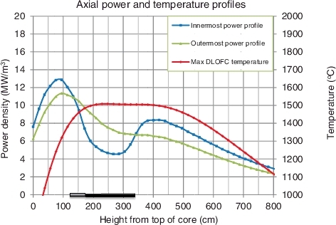
shows the axial equilibrium fission power density profiles for the inner and the outer-most fuel flow channels of a symmetric PBMR DPP-400 core, fuelled with a 16 g/pebble mixture of thorium and 20 a/o% LEU, with effective enrichment of 6.841 a/o%, in an OTTO fuelling scheme. The resulting axial DLOFC temperature is also presented on the right-hand scale. The power densities represent the average power density in each fuelling region in the axial fuel flow channel, which is relatively large, as opposed to the temperatures that represent discrete points in the material.
Figure 1. Standard axial power and maximum DLOFC temperature profiles for a PBMR-400 core, fuelled with a 16 g/sphere LEU-Th in an OTTO fuelling scheme.
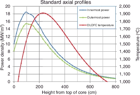
The following observations can be made from the above figure:
| • | As expected, the power in the innermost fuel flow channel is substantially higher than in the outermost fuel flow channel. This is a typical result of the cylindrical effect in an annular core with good neutron moderation in both the central and the external reflector and with control rods in the external reflector, as was explained in detail in [Citation8]. | ||||
| • | Both equilibrium power density profiles strongly peak at the top of the core to reach a maximum at 95 cm into the core, and then decrease sharply with increasing depth into the core. | ||||
| • | The maximum DLOFC temperature profile, driven by the axial power profiles, also peaks strongly near the top of the core to reach a maximum of 1911 °C at 229 cm into the core. | ||||
| • | The DLOFC temperature peaks about 100 cm below the power density peaks, and also dropped off much more slowly. This position of the DLOFC temperature peak below that of the power profile can be explained by the downward transfer of the heat by the coolant as it flows toward the bottom of the core. The mechanisms by means of which this phenomenon (together with the tendency for higher power densities adjacent to the central reflector) increases the maximum DLOFC temperature were explained in greater detail by Tchonang Pokaha and Serfontein [Citation8]. | ||||
3.2. Optimal placement of 10B in the central reflector
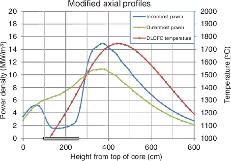
shows that the axial power density profiles peak close to the top of the core, resulting in a maximum DLOFC temperature profile with all the very high temperatures (>1400 °C) in the region between 76 and 500 cm into the core. The lower half of the core thus experiences only medium-high DLOFC temperatures and therefore contributes sub-optimally to the burden of evacuating the decay heat during a DLOFC. This suggests that it would be beneficial to suppress the power peak by placing a high 10B concentration in the central reflector, near to height the top of fuel core. In the first attempt, the 10B was placed right at the top of the core (i.e. height = 0 cm, down to 115 cm). However, this resulted in shifting the power peaks further down towards the middle of the core rather than suppressing these peaks. Therefore, the procedure shifted the maximum DLOFC temperature peak downwards, without flattening it substantially. Since Serfontein [Citation7] showed that for a six-pass core, excellent flattening of the maximum DLOFC temperature peak is obtained when the axial power peak is split into a peak near the very top of the core, a subsequent depression zone and a smaller peak lower down, as discussed above, the uniform 10B concentration was then shifted down to the region between 115 and 287 cm. This resulted in a small power peak in the innermost axial profile at 57 cm, followed by a much larger peak at 380 cm, as shown in , for a 10B concentration of 6.75 × 10⁻⁵ atoms/(barn.cm). This procedure reduced the maximum DLOFC temperature to 1745 °C, but nonetheless, this temperature is still much higher than the target of 1600 °C.
Figure 2. Modified axial power and DLOFC temperature profiles with 10B in the region 115–287 cm of the central reflector.
The 10B region was then shifted half a meter further down to the region between 172 and 345 cm, as shown on the core model in , in order to create the desired larger power peak at the top end smaller peak lower down. The B-10 concentration was then varied until the maximum DLOFC temperature was reduced to below 1600 °C, as shown in . This occurred at a 10B concentration of 6.75 × 10⁻⁶ atoms/(barn.cm).
Figure 3. Reactor geometry used for VSOP simulation with the B-10 placement.
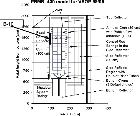
Figure 4. Modified power and maximum DLOFC temperature profiles with a 10B concentration of 6.75 × 10⁻⁶ atoms/(barn.cm) in the central reflector in the height-range of 172 and 345 cm below the top of the fuel core in order to reduce the maximum DLOFC temperature of the symmetric core.
4. Results
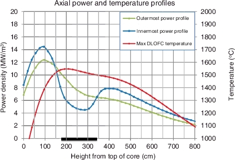
presents the results for the first 10B distribution that managed to reduce the maximum DLOFC temperature to below 1600 °C. Figure 4 shows both the inner and the outermost axial power profiles, and also the DLOFC temperature profile on a different scale for a 10B concentration of 6.75 × 10⁻⁶ atoms/(barn.cm) in the region between 172 and 345 cm from the top of the fuel core. A deeper than usual depression zone and a more pronounced second peak can be seen in the innermost power profile. When compared to the base case () where no poison was inserted in the central reflector, it is clear from that the poison in the central reflector also modulated the outermost power profile in the sense that the first peak near the top of the core is suppressed and the drop in power density, at the height of the second peak in the innermost profile, is also slower. However, this effect was not sufficient to actually create a second peak in the outermost profile. It follows that while the poison distribution in the central reflector also affects the power density in the outermost profile, its effect is limited. This was to be expected as the effect of the neutron poison is reduced with increasing distance from the poison.
The net result of manipulating the axial power profiles in this manner was an almost complete flattening of the DLOFC temperature peak, reaching a maximum value to 1548 °C after 56 h into the accident. These results were obtained at the cost of a loss in burn-up, which had to be compensated for by increasing the fuel enrichment from 6.841wt% to 7.293wt%, in order to restore the original burn-up.
Although these results are impressive, the first peak in the innermost power profile still appears to be too high, resulting a maximum DLOFC temperature profile peak, which does not have the desired flat top, but is rather skewed with an unnecessary high bump at 200 cm. In an attempt to further flatten the DLOFC temperature profile, some 10B was introduced in a 57 cm thickness above the initial suppression zone. This strategy seemed to produce positive results (reduction in the height of the first power peak, compensated by a slight increase in that of the second power peak) up to a 10B concentration of 0.544 × 10⁻⁶ atoms/(barn.cm) in the 57 cm region, producing a maximum DLOFC temperature of 1509 °C after 62 h into the accident. The results for this configuration are shown in . It indicates the axial power density and maximum DLOFC temperature profiles for a 10B concentration of 0.544 × 10⁻⁶ atoms/(barn.cm) in a 57 cm region above the suppression zone and 6.75 × 10⁻⁶ atoms/(barn.cm) in the suppression zone. This resulted in a slight increase in burn-up, which was removed by reducing the enrichment from 7.293wt% to 7.265wt%.
Figure 5. A symmetric maximum DLOFC temperature peak, achieved by modifying the power profiles with a 10B concentration of 6.75 × 10⁻⁶ atoms/(barn.cm) in the suppression region of the central reflector and a 10B concentration of 0.544 × 10⁻⁶ atoms/(barn.cm) in a 57 cm region above the suppression zone, in order to further reduce the maximum DLOFC temperature of the symmetric core.
The main objective of a previous article [Citation8] was to reduce the maximum DLOFC temperature to below 1600 °C, without adding poison to the central reflector, so that the solution would also be applicable to cores that do not have a central reflector. However, having failed in that endeavour, it was decided to place an appropriate 10B concentration in the central reflector for the current study, which unfortunately restricts the current solution to annular cores.
In order to compare the results obtained for both the symmetric and asymmetric cores as in the previous study, another study was added with the same 10B concentrations at the same positions, but for an asymmetric core. The asymmetric core was created by having a mixture of thorium and 15 a/o% LEU with effective enrichment of 2.575 a/o% in the inner two fuel flow channels of the core and a mixture of thorium and 20 a/o% LEU with effective enrichment of 9.864 a/o% in the outer three fuel flow channels. It must be noted that an asymmetric core adds an extra level of complexity to the system, because the two types of fuel types to be separated physically by some engineered means, and to some extent need to be prevented from mixing for their entire journey through the core. This can only be achieved by having extra structures in the core, which would have an influence on the neutron economy and could create added safety risks, for instance the risk that these structures could break, in which case the two fuel streams will no longer flow as designed. shows the axial power density and maximum DLOFC temperature profiles for the asymmetric core without B-10 in the central reflector [Citation8], together with the corresponding data for the radially symmetric core from .
Figure 6. Axial power and maximum DLOFC fuel temperature profiles for producing a lower maximum DLOFC temperature, shown on a separate scale, for both the radially symmetric and asymmetric LEU-Th fuel cycles.
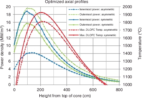
It is clear from this figure that the asymmetry strongly influenced the equilibrium power density profiles as the peak in the innermost profile for the symmetric core was substantially higher than for the outermost one, while the peak in the innermost profile of the asymmetric core was much lower than for its outermost profile. Because this would substantially reduce the distance over which most of the decay would have to be evacuated towards the external reflector during the DLOFC accident for the asymmetric case, it is surprising that the reduction in maximum DLOFC temperature was so small, i.e. from 1910 to 1810 °C. It suggests that the maximum DLOFC temperature is much less sensitive to manipulation of the radial profiles of the power density than to the manipulation of its axial profiles.
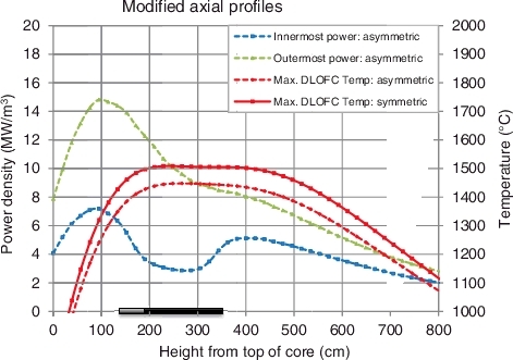
In an attempt to reduce the maximum DLOFC temperature further from the 1810 °C previously obtained with the asymmetric core to below 1600 °C, the same concentrations of 10B neutron poison were again inserted into the central reflector, as was done for the radially symmetric core. shows that the axial power DLOFC temperature profile is quite similar in shape to that of the symmetric core in , with the main difference being that the maximum DLOFC temperature for the asymmetric case of 1448 °C is substantially lower than 1509 °C for the symmetric case. This can be ascribed to the fact the asymmetry of the core already suppressed the power in the innermost part of the core, and the addition of the suppression zone by the inclusion of neutron poisons in the central reflector further suppresses the first power peak at the top of the core, making the second power peak's height closer to that of the first. As observed with the symmetric core, the closer in height the second innermost power peak gets to the first, the less its likelihood to flatten the DLOFC temperature profile, suggesting that a change in the neutron poison concentration in order to increase the difference in heights between the two innermost power peaks would produce even better results. Once more these results were obtained at the cost of a loss in burn-up, which had to be compensated for by increasing the fuel enrichment from 2.575 to 3.483 a/o% in the inner part of the core and from 9.864 to 9.968 a/o% in the outer part of the core, in order to restore the original burn-up.
Figure 7. The asymmetric core with modified power and temperature profiles with a 10B concentration of 6.75 × 10⁻⁶ atoms/(barn.cm) in the suppression region of the central reflector and a 10B concentration of 0.544 × 10⁻⁶ atoms/(barn.cm) in a 57 cm region above the suppression, to further reduce the maximum DLOFC temperature of the asymmetric core.
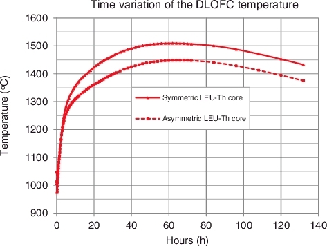
presents the time dependence of the DLOFC temperature for both the symmetric and the asymmetric cores, with the same 10B concentration of 6.75 × 10⁻⁶ atoms/(barn.cm) in the suppression region of the central reflector and a 10B concentration of 0.544 × 10⁻⁶ atoms/(barn.cm) in a 57 cm region above the suppression zone. The two graphs have the same shape, reaching their respective maximum values of 1509 °C after 62 h, 1448 °C after 64 h into the accident for the symmetric and the asymmetric core, respectively.
Figure 8. Time profiles for maximum DLOFC temperatures with a 10B concentration of 6.75 × 10⁻⁶ atoms/(barn.cm) in the suppression region of the central reflector and a 10B concentration of 0.544 × 10⁻⁶ atoms/(barn.cm) in a 57 cm region above the suppression zone.
5. Discussion and conclusion
During the course of this optimization study aimed at reducing the maximum DLOFC temperature of a PBMR-400 fuelled with a mixture of thorium and LEU, the followings were found:
| • | The 10B neutron poison concentration in the central reflector sharply reduced the maximum DLOFC temperatures, but also reduced in the burn-up. In order to restore the burn-up, the enrichment of the fresh fuel had to be increased. | ||||
| • | Although the neutron poison was introduced in the central reflector, and this had the most significant effect in the innermost power density profiles, its effect was still substantial in the outermost power profiles, showing substantial neutronic coupling between the inner and the outer parts of the core. However, this coupling was substantially less for the asymmetric core in that the shape of the outermost power density profile appears substantially dissimilar to that of the manipulated innermost profile. This was probably caused by the fact that asymmetry ‘pushed’ the neutron flux out towards the external reflector, which reduced the neutron flux at the position of the poison in the central reflector and thus reduced the importance of this poison concentration. | ||||
| • | The flattening of the DLOFC temperature profile was not achieved by flattening the axial power profiles, but rather by splitting the large peak in the innermost power profile into a somewhat smaller peak at the top of the core, followed by a depression zone and an even smaller peak in the bottom half of the core. This has to do with the fact that the long time lag of about 60 h from the start to the DLOFC accident to the maximum DLOFC temperature causes the decay heat from these two power peaks to diffuse through the core and thus to merge into one flattened DLOFC temperature profile. | ||||
| • | There is a strong relation between the ratio of the heights of the peaks in the innermost power profile and the flattening of the DLOFC temperature profile in that the first innermost power peak should be substantially higher than the second one, in order to produce a flat temperature profile. This has to do with the fact that the equilibrium core is substantially cooler near the top and can thus safely absorb more decay heat near the top. | ||||
Neutron poison was successfully used in combination with a mixture of LEU and thorium to reduce the maximum DLOFC temperature of a medium-sized annular core pebble-bed reactor (PBMR-400). Thorium in the fuel helped to reduce the peaking factor, while the neutron poison distribution shaped the axial power profile.
The study was conducted with 10B for the sake of simplicity. However, in practice 10B, which is a burnable poison, will have to be replaced with a non-burnable poison, such as natural hafnium, in order to maintain the poison concentration over the life of the plant. This problem does not arise in the case of this study as VSOP 99/05 does not follow the depletion of 10B in the central reflector but rather considers its concentration to remain the same, which is not the case in practice.
The following follow-up studies are proposed:
| • | A comparative study of different neutron poison distribution in the central reflector, the external reflector, or even both reflectors, in order to optimize the power profiles even further in terms of burn-up, equilibrium and accident fuel temperatures. | ||||
| • | The increase in fuel enrichment could increase fuel cost. Therefore, a trade-off between reducing DLOFC temperatures even further by increasing the neutron poison densities further and limiting fuel cost would be an interesting study. | ||||
| • | A detailed study on the optimum asymmetry level of the core together with a clear relationship between the heights of the first and second peaks of the innermost power profile. | ||||
| • | Repeating the optimization process with substantially higher fuel enrichments. Higher enrichment fuels would reduce fuel manufacturing cost, due to the much higher burn-ups and thus much higher cumulative energy produced per fuel sphere that would be achieved. However, it would also sharply increase the peakedness of the axial power profiles, which will increase the maximum DLOFC temperatures. Therefore, higher poison concentrations and different poison distributions will have to be used in order to restore the lower maximum DLOFC temperatures. | ||||
| • | Repeating the optimization process for cylindrical cores that do not have central reflectors. All poisons will thus have to be placed in the external reflectors. This will complicate matters by shifting the radial power inwards, which would partly offset the reductions in maximum DLOFC temperatures that would be obtained by flattening the peaks in the axial maximum DLOFC temperature profiles. | ||||
Acknowledgments
This work is based on research supported by the South African Research Chairs Initiative of the Department of Science and Technology and National Research Foundation of South Africa [grant number 61059].
Any opinion, finding, conclusion or recommendations expressed in this material are those of the author(s) and the NRF does not accept any liability in this regard.
Disclosure statement
No potential conflict of interest was reported by the authors.
Additional information
Funding
References
- Kania MJ, Nabielek H, Verfondern K, et al. Testing of HTR UO2 TRISO fuels in AVR and in material test reactors. J Nucl Mater. 2013;441:545–562.
- Reutler H, Lohnert GH. The modular high-temperature reactor. Nucl Technol. 1983;62:22–30.
- Reutler H, Lohnert GH. Advantages of going modular in HTRs. Nucl Eng Des. 1984;78(2):129–136.
- Zhang Z, Wu Z, Wang D, et al. Current status and technical description of Chinese 2 x 250MWth HTR-PM demonstration plant. Nucl Eng Des. 2009;239:1212–1219.
- Reitsma F. The pebble bed modular reactor layout and neutronics design of the equilibrium cycle. In: Proceedings of PHYSOR 2004 –The Physics of Fuel Cycles and Advanced Nuclear Systems: Global Developments; 2004 Apr 25–29; Chicago (IL): American Nuclear Society. [CD-ROM].
- Hansen U, Schulten R, Teuchert E. Physical properties of the “Once Through Then Out” pebble-bed reactor. Nucl Sci and Eng. 1972;47:132–139.
- Serfontein DE. Sharp reduction in maximum fuel temperatures during loss of coolant accidents in a PBMR-400 core, by means of optimised placement of neutron poisons. Nucl Eng Des. 2014;271:492–498.
- Tchonang Pokaha M, Serfontein DE. Using thorium to reduce the maximum fuel temperatures during depressurized loss of coolant accidents in a once-through-then-out (OTTO) PBMR DPP-400 core. J Nucl Sci Technol. 2017;54(5):589–599.
- Lamarsh JR, Barata AJ. Nuclear reactor fuels. Introduction to nuclear engineering. 3rd ed. Upper Saddle River, New Jersey (NJ): Prentice-Hall, Inc; 2001. p. 327.
- van Dam H. Long-term control of excess reactivity by burnable particles. Ann Nucl Energy. 2000;5;27(8):733–743.
- Kloosterman JL. Application of boron and gadolinium burnable poison particles in UO2 and PUO2 fuels in HTRs. Ann Nucl Energy. 2003;30:1807–1819.
- Tran HN, Kato Y. An optimal loading principle of burnable poisons for an OTTO refueling scheme in pebble bed HTGR cores. Nucl Eng Des. 2009;239:2357–2364.
- Rütten HJ, Haas KA, Brockmann H, et al. V.S.O.P. (99/05) (release 2): computer code system for reactor physics and fuel cycle simulation. Ju¨lich: Institut fu¨r Sicherheitsforschung und Reaktortechnik [Software]; 2007.
- Serfontein DE. Deep burn strategy for the optimized incineration of reactor waste plutonium in pebble bed high temperature gas-cooled reactors [dissertation]. Potchefstroom: North-West University; 2011.