
ABSTRACT
Thermal-hydraulic performance is a challenging issue in helium-cooled ceramic breeder (HCCB) blanket design due to the extremely complicated working environment and the strict limits of materials temperature. The heat loads deposited on the HCCB blanket comprises of severe surface heat flux from plasma and the volumetric nuclear heat from neutron irradiation, which can be exhausted by the built-in cooling channels of the components. High pressure helium with 8 MPa, distributed from the coolant manifolds is employed as coolant in the blanket. The design and optimization of the manifolds configuration was performed to guarantee the accurate flow control of helium coolant. The flow distribution in the coolant manifolds was investigated based on the structural improvement of manifolds aiming at overall uniform mass flow rates and better flow streamline distribution without obvious vortexes. The peak temperature of different functional materials in the blanket under normal operating condition is below allowable material limits. It is found that the components in the current blanket module could be cooled effectively under the intense thermal loads due to the updated design and optimization analysis of manifolds.
1. Introduction
CFETR is proposed to address the technological and scientific gaps between International Thermonuclear Experimental Reactor (ITER) and the future fusion demonstration power plant and to facilitate the realization of the sustainable, carbon-free, and clear fusion energy. The missions of CFETR are to demonstrate the tritium self-sufficiency ability, associated thermal loads removal, and adequate shielding capability [Citation1–3]. To achieve these goals, the helium-cooled ceramic breeder (HCCB) blanket was designed and introduced as one promising concept blanket for CFETR. Performance analyses of the previous blankets design for CFETR on thermal-hydraulic, neutronics, and thermal-mechanical are also carried out [Citation4–6]. To validate the design of the updating structure of the CFETR HCCB blanket, integrated thermal-hydraulic performance evaluation was done and presented. Based on the mass flow rates obtained from the thermal-hydraulic analysis, the design and optimization of manifolds was performed to realize balanced and uniform mass flow rates without any kind of vortexes. The peak temperatures of the main components inside blanket module were also calculated to check and verify the feasibility of the cooling system configuration.
2. Design description
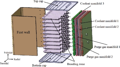
The blanket module consists of the first wall (FW), caps, breeder units (BU), manifolds, and the associated gas inlet and outlet pipelines, as depicted in . The module has 800 mm radial thickness and 1260 mm poloidal height with a toroidal width of 1010 mm. The thickness of the U-shaped FW is 25 mm coated with 2 mm tungsten armor in the middle plasma-facing surface and the external size of FW is consistent with the blanket module. The top and bottom cap is a plate with a thickness of 30 mm. The space out of the BU array structure is filled with beryllium pebbles inside the module. There are five stages of manifolds located at the back of the blanket module for collecting and distributing helium coolant including three coolant manifolds and two purge gas manifolds. The design of the cooling channels in each component and the design of the manifolds and BU structure can be referred to [Citation7]. Fluid guide cylinders are adopted first as efficient supports to strengthen the structure and second as an effective method to optimize the helium flow distribution to avoid obvious vortexes for the sake of uniform mass flow rates. The basic arrangement of the fluid guide cylinders between the two adjacent manifolds are the same and the arrangement of the fluid guides are obtained through iterations between design and calculations. The compact design of the manifolds with a low-space occupation helps leave relatively more space for the BU design and arrangement.
Figure 1. Present design of the CFETR HCCB blanket.
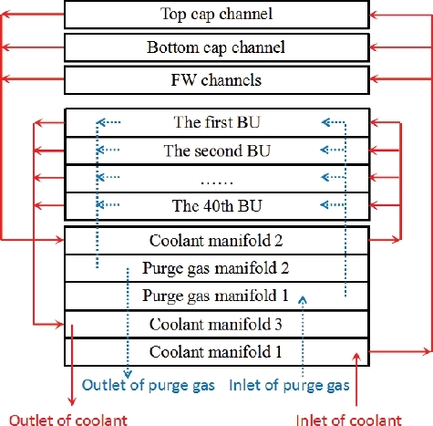
Detailed coolant flow schemes in the blanket module are shown in . The helium coolant is first pumped into the first coolant manifold and flows into the built-in channels of FW and the two caps in parallel. The helium out of the FW and cap channels is gathered into the second coolant manifold and then it is distributed to the BUs averagely to cool the related components. Coolant flowing out of the BUs is collected in the third coolant manifold and finally flows out of the blanket via the main coolant outlet pipe penetrating the back plate. The purge gas manifolds were just used for distributing and collecting purge gas and were not included in this work.
Figure 2. Flow schemes of coolant and purge gas.
The 4 × 10 BU arrays built in toroidal and poloidal direction are of great benefit to design, processing, and maintenance in the blanket module. The structure of the 10 layers of BUs is the same while the heat transfer boundary of the 10 layers of BUs in poloidal direction is not exactly the same. Thus, two kinds of computational models were established in ANSYS Workbench for the two kinds of heat transfer modes [Citation7]. The standard κ − ϵ model combined with scalable wall function was used in the analysis with the non-dimensional distance y+ ranging from 40 to 60 for all the cases. The pipe inlet temperature of FW, cap, and BU are 300, 300, and 427.3 °C, respectively, according to the iteration results of the theoretical calculations performed before. Surface heat flux and the volumetric nuclear heat were used as the heat loads. Flow distribution was calculated and optimized by adjusting the structure of the manifolds, and the temperature distribution of the materials adopted in the blanket module are achieved through the calculations by ANSYS CFX code.
3. Fluid analysis and optimization
The thermal-hydraulic analysis of the blanket was performed to find out the temperature distribution and to make clear the flow distribution in the coolant manifolds by the ANSYS CFX code. Purge gas manifolds only play the role of distributing and collecting purge gas and are not considered in this work. Mass flow rates are the critical index to evaluate the design of the manifolds. The flow characteristics of helium coolant in the first coolant manifold and the second coolant manifold were simulated in terms of the mass flow rates and the cooling effects evaluation from the velocity streamline distribution. The poor cooling zones and bad flow distribution zones with a lot of vortexes have been optimized through adjusting the location of the inlets/outlets or adding some fluid guide cylinders to achieve equally distributed flow and better cooling effects.
3.1. The first coolant manifold
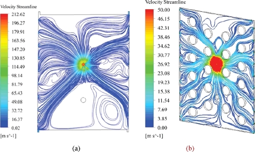
The primary design of the first manifold has 20 outlets and 1 inlet. The inlet is located near the center of the external back plate, as shown in (a). The location adjacent to the inlet is penetrated by coolant pipe. The mass flow distribution is not uniform, and the four sticking out corners marked as red-dotted box will affect the coolant flow of the manifold. Some vortexes appear from the streamline contour, as illustrated in and (a). The special locations of the four corners in the primary design will weaken the cooling effect of the coolant flowing outlets and need to be reconsidered. Iterations of the first manifold have been done between design and calculations to optimize the flow distribution until much more uniform mass flow rates with better flow behavior were obtained. The optimized flow domain of the first manifold is presented in (b) with 22 outlets and still 1 inlet. Four groups of fluid guides were added to guide the streamline and four corners were removed. The mass flow rate of the first manifold after structural improvement is illustrated in within a preferable deviation range. Reasonable flow distribution and better cooling effect were obtained with balanced mass flow rates without any kind of obvious vortexes in the velocity streamline profile, as shown in (b).
Figure 3. The first coolant manifold design: (a) primary design; (b) optimization design.
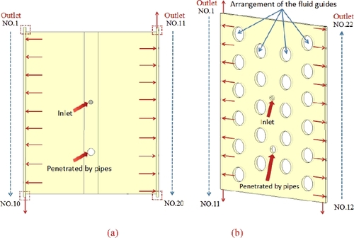
Figure 4. Mass flow rates of the outlets of the first coolant manifold.
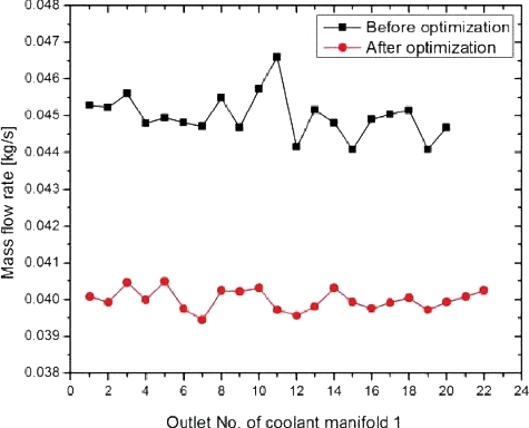
Figure 5. Helium streamline with velocity of the first coolant manifold: (a) primary result; (b) optimization result.
3.2. The second coolant manifold
The primary design of the second manifold had 22 inlets and 40 outlets, as shown in (a). The calculated flow distribution with higher deviation is shown in . The maximum and minimum flow rates are 0.027 kg/s and 0.013 kg/s with the deviation from the average rate 0.022 kg/s of 122% and 59%, respectively. The mass flow rates of the outlets No.3, 6, 9, 27, and 38 are significantly less than the average rate 0.022 kg/s with the deviation of 72%, 86%, 73%, 66%, and 61%. The mass flow rates of the outlets No.13, 22, 23, 31, and 32 are significantly greater than the average rate 0.022 kg/s with the deviation of 118%, 122%, 125%, 134%, and 123%. A lot of vortexes can be observed from the velocity streamline results, especially for the locations near the outlets with higher deviation rates, as shown in (a). It is found that locations with lower mass flow rates will produce vortexes easier, which should be avoided in the structural design. The high deviations from the average flow rate make the coolant flow badly distributed, and some locations on the manifold cannot be cooled very well with severe vortexes [Citation8].
Figure 6. The second coolant manifold design: (a) primary design; (b) optimization design.
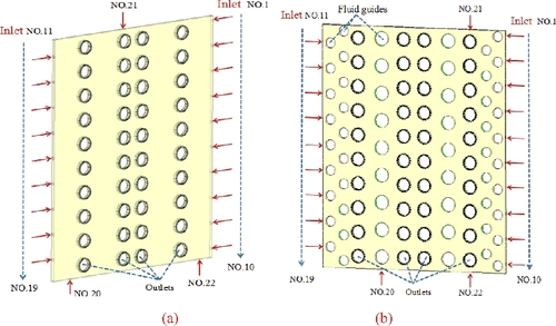
Figure 7. Mass flow rates of outlets of the second coolant manifold.
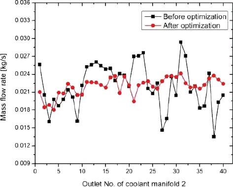
Figure 8. Helium streamline of the second coolant manifold: (a) primary result; (b) optimization result.
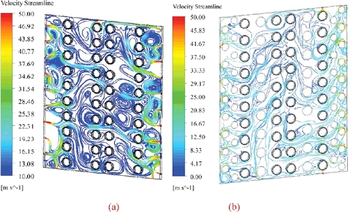
After iterations of calculation and optimization, six groups of fluid guides were added to guide the coolant flow inside the second coolant manifold and the location of the three inlets was changed, as shown in (b). In addition, the total number of the inlets and outlets of the manifold did not change. The calculated helium coolant flow is summarized in . It shows that the maximum and minimum flow rates are 0.024 kg/s and 0.018 kg/s with the deviation of 109% and 82%, respectively. This deviation at different outlets can be considered to be acceptable without optimization in the preliminary design. The heavy vortexes of the previous manifold design was greatly improved and the coolant flow is overall uniformly distributed with a better velocity streamline as depicted in detail in (b). As the third coolant manifold was connected in series with the second coolant manifold and was designed based on the optimization of the second coolant manifold with the same arrangements of the fluid guides, the third coolant manifold was not considered. Moreover, the preliminary design and optimization process of the coolant manifolds can provide good reference and data to promote the next-step blanket manifold design and updation for CFETR.
4. Thermal analysis
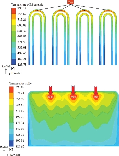
The purpose of the thermal calculation is to find out the temperature distribution of different functional components in the blanket. The temperature peaks of different materials adopted in the blanket require to be obtained to make clear the cooling effect of the design arrangements of the channels. To keep the maximum temperature of the blanket materials below the corresponding permissible temperature limits is an important index to adjudge the design. The maximum calculated temperature of the W armor and FW steel are conservatively calculated to be 550.8 and 548.7 °C as shown in , which were both within the temperature limits of the corresponding materials. The peak temperature of the two materials appears closely on the top surface of FW in the three-dimensional finite element model. The maximum predicted temperature of Li4SiO4 pebble bed is 790.1 °C and appears at the front side of the BU due to the special location close to plasma with high surface heat flux and volumetric nuclear heat. The maximum predicted temperature of Be is 599.8 °C and happens at the front side of the BU, which is located far away from the coolant channels with poor cooling effect. The maximum temperature of Li ceramic and Be, shown in , were both below the corresponding material temperature limits. The peak temperatures of the concerned functional materials are all below the corresponding material temperature limits [Citation9,Citation10], and the locations near plasma and far away from the cooling channels should be paid much more attention in the blanket design.
Figure 9. Temperature distribution on FW in radial-toroidal crosssection.
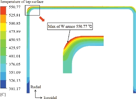
Figure 10. Peak temperature of Li ceramic and Be.
5. Conclusion
The flow analysis of helium coolant from the coolant manifolds and the temperature distribution of different functional materials for CFETR HCCB blanket were investigated. The configurations of the first coolant manifold and the second coolant manifold have experienced iterations of design and analysis to realize uniform mass flow rates of the helium coolant. The simulation results show the flow distribution of the first coolant manifold and the second coolant manifold were improved greatly with the overall uniform mass flow rates and good flow streamline distribution without obvious vortexes by means of adjusting outlets/inlets locations or sizes and adding fluid guide cylinders. The optimized coolant manifolds with equally distributed helium coolant can be very beneficial to the cooling effect for the in-box components. The temperature peaks of concerned functional materials in the blankets under normal operating condition are within allowable material limits. It is indicated that the HCCB blanket could be cooled effectively under the intense thermal loads in the preliminary design.
Acknowledgments
The authors wish to express their gratitude to all the members of CFETR design team. This work was financially supported by the National Key R&D Program of China [grant number 2017YFE0300604], [grant number 2017YFE0300503].
Disclosure statement
No potential conflict of interest was reported by the authors.
Additional information
Funding
References
- Song YT, Wu WY, Du SJ, et al. Tokamak engineering mechanics. Berlin Heidelberg: Springer-Verlag; 2014. p. 99–156.
- Wan YX, Li JG, Liu Y, et al. Overview of the present progress and activities on the CFETR. Nucl Fusion. 2017;57:102009.
- Song YT, Wu ST, Li JG, et al. Concept design of CFETR tokamak machine. IEEE Trans Plasma Sci. 2014;42(3): 503–509.
- Lei MZ, Song YT, Ye MY. Thermal hydraulic analysis of the HECLIC blanket breeder unit for CFETR. Int J Energy Res. 2015;39(3): 370–376.
- Xu K, Ye MY, Song YT, et al. Neutronic analysis for CFETR with modular helium cooled lithium ceramic blanket. Proceedings of the 2017 25th International Conference on Nuclear Engineering (ICONE25); 2017 May 14-18; Shanghai, China: American Society of Mechanical Engineers; 2017. p. V005T05A035-V005T05A035.
- Lei MZ, Song YT, Ye MY, et al. Conceptual design of a helium-cooled ceramic breeder blanket for CFETR. Fusion Sci Technol. 2015;68(4):772–779.
- Lei MZ, Xu SL, Guo C, et al. Design and thermal-hydraulic evaluation of helium-cooled ceramic breeder blanket for China fusion engineering test reactor. Int J Energy Res. 2017;42(4): 1657–1663.
- Ahn MY, Ku DY, Cho S, et al. Thermo-hydraulic analysis on Korean helium cooled solid breeder TBM with updated back manifolds design. Fusion Eng Des. 2011;86:2289–2292.
- Hirai T, Pintsuk G. Thermo-mechanical calculations on operation temperature limits of tungsten as plasma facing material. Fusion Eng Des. 2007;82(4): 389–393.
- Xu Z, Rey J, Fischer U, et al. Development of a DEMO helium cooled pebble bed (HCPB) breeder unit featured in flat plates with meandering channels. Germany: Forschungszentrum Karlsruhe; 2005. (Report no. 7181).