
 ?Mathematical formulae have been encoded as MathML and are displayed in this HTML version using MathJax in order to improve their display. Uncheck the box to turn MathJax off. This feature requires Javascript. Click on a formula to zoom.
ABSTRACT
We have started an experimental program to measure activation cross sections systematically in the proton-induced spallation reaction in structural materials commonly used in high-intensity proton accelerator-based facilities, such as Japan Proton Accelerator Research Complex (J-PARC). As the first step of the program, aluminum (Al) was chosen to verify the adequacy of the measurement technique implemented in a J-PARC proton beam environment because data of Al have been relatively well studied both by experimental measurement and simulation. Activation cross sections of 7Be, 22Na, and 24Na in Al were measured at proton energy points from 0.4, 1.3, 2.2 to 3.0 GeV, which could be delivered smoothly from the synchrotron. The validity of experimental data has been verified by introducing an effective proton numbers determination procedure. We compared the measured data with existing experimental data, the evaluated data (JENDL-HE/2007), and the calculations with several intra-nuclear cascade models by the Particle and Heavy Ion Transport code System (PHITS) code. Although the experimental data agreed with JENDL-HE/2007, the calculations underestimated about 40%. This could come from the evaporation model (generalized evaporation model) being implemented in the PHITS code. We found that the calculations agreed with the experimental data by an upgraded PHITS code.
1. Introduction
A reliable set of nuclear cross section data plays a fundamental role in nuclear designs for proton-induced spallation neutron source facilities, such as Japan Proton Accelerator Research Complex (J-PARC) [Citation1], and also assessments of decommissioning process of the accelerator facilities from both better performance and safety management points of view. To measure proton-induced reactions, the activation technique is primarily effective to provide nuclear productions cross sections in a spallation reaction process. Although, there have been a considerable amount of experimental data reported at several facilities, still, more systematic data are needed in versatile fashions, in particular, in a GeV energy region, which is used commonly in spallation facilities. Titarenko et al. [Citation2] reported experimental data extensively at the Institute for Theoretical and Experimental Physics on many elements with 0.04–2.6 GeV, although they were not given as absolute values but relative values to some references. Furthermore, they were not completely covered in the important energy region and materials concerning the GeV proton accelerator facilities. In 1990s, Michel et al. [Citation3] had measured the cross sections for various materials; they were not systematic measurements. On the other hand, model calculations along with nuclear data library evaluations have recently been in significant progress. However, they are not always consistent with each other among data, and needs for validation with reliable experimental data have been addressed.
Thus, we have set up a program on systematic measurement of proton-induced activation cross sections at J-PARC on structural materials composed in a spallation source facility. The objective materials include primarily spallation target, proton beam window, proton beam transport, components, confinement vessels, supporting structures, biological shielding, etc. with a scope as wide as possible.
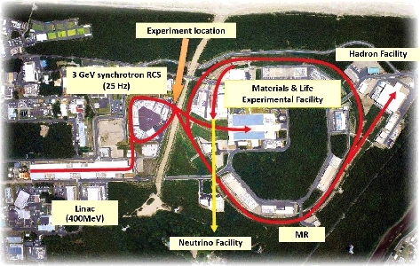
As the first step of the program, aluminum (Al) was chosen to verify the adequacy of the measurement technique applied in the J-PARC proton beam environment, whose layout is shown in , because data concerning Al have been relatively well studied both experimentally and by simulation. We have selected incident proton energies of 0.4, 1.3 , 2.2, and 3.0 GeV, which are delivered smoothly from the 3 GeV Rapid Cycling Synchrotron (RCS) [Citation4] of J-PARC accelerator.
Figure 1. J-PARC facility layout.
The experiment was carried out at a beam dump line [Citation5] near the beam extraction from the RCS. Activation cross sections of 7Be, 22Na, and 24Na in Al were measured and the data were compared with existing experimental data, model calculations with the Particle and Heavy Ion Transport code System (PHITS) code [Citation6], and evaluated nuclear data of JENDL-HE/2007 [Citation7]. Although the activation technique was well established, we have developed a method to determine the precise proton number for irradiation. The adequacy of the present experimental procedure was examined by comparing the measured data with existing experimental data. Also, we have examined the validity of simulations and nuclear data by using the measured data.
In this paper, details of the experiment, analysis procedure, and the estimation of the irradiated number of protons are described.
2. Experiment
2.1. Sample irradiation set-up
shows a schematic layout of the experimental configuration showing the proton beam line from the RCS and the beam dump. The sample for irradiation was placed in a chamber installed in the beam line. depicts a detailed structure of the chamber for sample irradiation.
Figure 2. A schematic layout of the experimental location in J-PARC. A rectangular indicated by the arrow shows the chamber position.
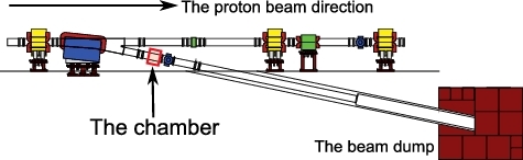
Figure 3. A chamber views. (a) the front view of the chamber; (b) the side view of the chamber.
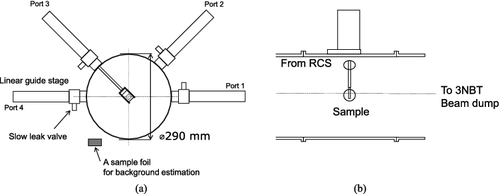
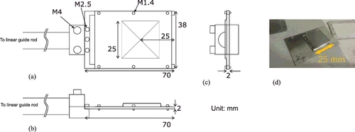
To estimate background neutron radiation, which might contribute to sample activation, during operation, an Al sample was placed on the outside of the stage as shown in . A liner stage guide as shown in was utilized to insert and retract the irradiation samples. Four sets of stacked four thin Al foils with dimensions 0.1 mm×25 mm×25 mm were prepared. The picture of one of the four sets is shown in . Each of them was sandwiched by two Al plates having dimensions 38 mm × 60 mm × 0.1 mm. The typical error for 0.1 mm sample thickness is ±10% [Citation8].
Figure 4. A schematic and real view of sample holder. (a–c) Drawings; (d) A real view of the sample and the holder.
The set of stacked Al sample foils was inserted into the irradiation position by using the ports in order of the respective proton energy. Before sample irradiation, proton-beam tuning of the accelerator and the beam transport through the sample position were performed utilizing the beam dump.
2.2. Sample irradiation
The experiment was carried out at the beam dump placed at the extraction of the RCS in J-PARC, as shown in . The Al samples were irradiated by 0.4, 1.3, 2.2, and 3.0 GeV protons. The 0.4 GeV proton beam which was injected from the linear accelerator of J-PARC to the RCS was extracted without acceleration by the RCS. The 3 GeV proton was primarily extracted from the RCS. The 1.3 and 2.2 GeV protons were delivered from the RCS acceleration by changing the extraction timing of kicker magnet. The proton-beam profile was monitored by a Multi-Wire Profile Monitor (MWPM), which was placed in the beam transport line.
By observation of the beam-width with the MWPM, it was shown that the proton-beam width at the sample foil position was smaller than 6.5 mm as one standard deviation where the distribution of proton is assumed to be the Gaussian. The proton-beam center was adjusted so as to irradiate a center of the sample foil. It should be noted that although in general the beam position was very stable during irradiation, there should be fluctuation time by time and proton energy by energy.
Beam current was monitored by current transformers, which were installed in the beam line before the sample irradiation place. The number of protons per shot was 6 × 10¹² at 150 kW operation of J-PARC. A repetition rate was set to 0.4 Hz to avoid the sample foils from melting, which was evaluated by simplified two-dimensional heat equation. Proton-beam parameters for the irradiation are summarized in . Uncertainties for beam energy, number of protons, and proton-beam widths were 0.27%, 3%, and 5%, respectively.
Table 1. Proton-beam parameters for irradiation
2.3. Activation cross section derivation
2.3.1. γ-Ray spectral measurement
After the irradiation, samples were removed from the folders and dismantled on site. Decay γ-rays from the irradiated samples were measured by a high pure germanium detector (HPGe; ORTEC GEM80P4-95-ST), which has an 80% relative efficiency to NaI(Tl). The main activation products in Al are 7Be, 22Na, and 24Na, the properties of which are summarized in . Decay data were taken from the latest IAEA Nuclear Data Services [Citation9].
Table 2. Properties of activation products
γ-Rays from sample foils were periodically measured, whose interval was from two hours to a day. The sample foil was mounted on the acrylic spacer to keep the detector-to-sample geometry rigidly. The distance between the sample position and the HPGe head was about 100 mm. Saturated radioactivity at the time of irradiation end for each product was deduced using the following equation: (1)
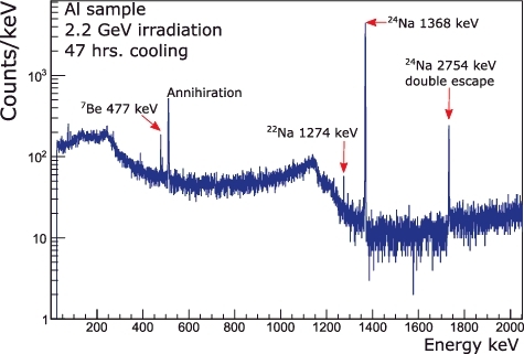
(1) where C is the count of γ-rays peak, λ is the decay constant, ti is the irradiation time, tc is the cooling time, tm is the measurement time, ε is the detection efficiency, b is the branching ratio of decay γ-rays, and μ is the γ-ray self-absorption coefficient of the sample in the sample. Detector efficiency of the HPGe was measured by using an 152Eu standard γ-ray source, which was put in the same position as the samples. Typical γ-rays spectrum is shown in .
Figure 5. Typical spectrum of Al 47 hours after irradiation with 2.2 GeV proton.
The main systematic uncertainty contributors are shown in .
Table 3. Table of uncertainties
The reaction rate R for specific spallation product nuclide, such as 7Be, can be calculated by (2)
(2) where Np is the number of protons irradiated. Finally, the production cross section was derived from the following equation:
(3)
(3) where n is the product of the number density of the sample and its thickness, given as cm−2. The dead-time correction for γ-ray measurements was performed.
From Equation (Equation2(2)
(2) ), the Np plays a key role in deriving the cross section. In the irradiation, it is expected that the proton beam has a Gaussian-like profile, as described in the irradiation set-up, so as not to assure all protons hit the sample. To arrive at a correct number of protons for irradiation, the process we took is described as follows:
2.3.2. Proton number determination
The number of protons bombarding the foil was derived by using image data taken by an imaging plate (FUJIFILM BAS-SR2040), which corresponds to a two-dimensional distribution of radioactivity on the foil. In -2, an image of activation on a foil taken by imaging plate (IP) is shown. It could be assumed that all radioactivity distributions in the sample foils were identical to the proton profile as long as there was no prominent change in the proton-beam optics. A possible profile of proton beam on the foil is schematically drawn in-1. Here, the proton-beam profile could be assumed as the Gaussian distribution, which could be assured from measurements of beam-profile monitors.
Figure 6. A schematic drawing of the proton number correction (6-2) and a real image of the imaging plate (6-1).
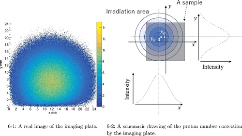
The image was taken by placing irradiated samples onto the imaging plate and exposing for a few days. The position of the proton-beam center was estimated to be the maximum value of IP events. By fitting of the Gaussian to images projected to each axis at the beam-center position, the widths of Gaussian profiles were determined. The proton-beam fractions were derived by integrating the distribution function over the sample area. As a result, the fraction of proton beams on the sample foils ranged from 79% to 100% depending on the proton-beam energy. This fraction was used for the final correction of the cross section determination.
3. Results
The obtained cross sections are shown in .
Table 4. The activation cross sections. Only statistical uncertainty is shown
They are plotted in (a–c) for 7Be, 22Na, and 24Na, respectively, and compared with existing experimental data available.
Figure 7. The measured activation cross sections. This works (full circle) and other experiments (other symbols) taken from EXFOR [Citation3,Citation10–18] data are plotted. (7-1) 27Al(p, X)7Be (7-2) 27Al(p, X)22Na (7-3) 27Al(p, X)24Na.
![Figure 7. The measured activation cross sections. This works (full circle) and other experiments (other symbols) taken from EXFOR [Citation3,Citation10–18] data are plotted. (7-1) 27Al(p, X)7Be (7-2) 27Al(p, X)22Na (7-3) 27Al(p, X)24Na.](/cms/asset/a2b56996-5265-4f92-a0cd-2a239657496d/tnst_a_1461694_f0007_oc.jpg)
The present data are generally in good agreement with data by Titarenko et al., which have been reported in a wide energy range. It is shown that experimental errors of the present measurement are relatively small among those data. This consistency in experimental data for the reactions in Al is a good proof for the quality of the present experimental procedure at J-PARC.
4. Status of PHITS simulation for spallation products
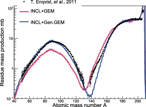
As a computer simulation code, PHITS for particle transportation has been widely used in many areas relevant to nuclear reaction simulation. We have examined the adequacy of cross section prediction capability of PHITS by comparing with the experimental data. The PHITS version 2.88 was employed to calculate the activation cross sections of Al with two intra-nuclear cascade models (Bertini [Citation19] and the Liège intranuclear cascade (INCL) [Citation20]) and one high-energy nuclear cascade model (Jet AA Microscopic Transport Model (JAM) [Citation21]). Generalized Evaporation Model (GEM) [Citation22] was used as the evaporation process in the calculations. A simple geometry was employed as follows: a proton beam with a circular shape of 10 mm diameter was injected into an Al disk having 20 mm diameter and 0.1 mm thickness. A correction for recoiled nuclei from the sample was estimated. It was found that there were negligibly small so that no correction was done for it. It is notable that the GEM in PHITS is different in treatment for Coulomb potential from the evaporation model originally developed [8], which was labeled as Genuine GEM (Gen.GEM). Implementing Gen.GEM into PHITS, the residue-mass production cross sections for the 208Pb+p reaction [Citation23] are shown in . shows that INCL + Gen.GEM ((color online) blue line) reproduces the existing experimental data well rather than INCL + GEM ((color online) red line), though they still have a discrepancy in 130 ≤ A ≤ 150. INCL + GEM, however, is in good agreement with the range A ≤ 140.
Figure 8. (color online). Residue mass production of 208Pb+p reaction.
5. Discussion
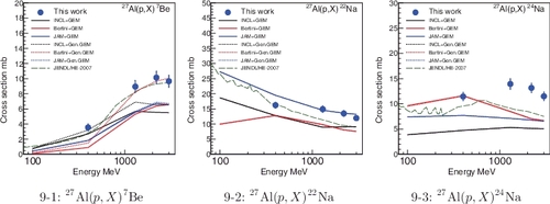
In (1–3), the present measured data, PHITS calculations, and JENDL/HE evaluated files for the activation cross section for 27Al(p, X)7Be, 27Al(p, X)22Na, and 27Al(p, X)24Na are shown, respectively. Here, (p, X) is denoted as a total reaction process producing radioactivities of interest.
Figure 9. (color online). The measured, calculated, and evaluated activation cross sections. Same calculation results were obtained for the cross sections of 27Al(p, X)22Na and 27Al(p, X)24Na. (a) 27Al(p, X)7Be (b) 27Al(p, X)22Na (c) 27Al(p, X)24Na.
5.1. 7 Be production
All PHITS calculations underestimate the experiments except that with JAM + GEM below 400 MeV. Especially, Bertini + GEM calculation is significantly underestimated. On the other hand, INC models with Gen.GEM ones agree on the experiments relatively well. In particular, INCL + Gen.GEM is in good agreement with the experiment at 400 MeV. Above 1 GeV, Bertini + Gen.GEM case represents the experiment within uncertainty. JENDL/HE-2007 agrees well with the present data within uncertainties.
5.2. 22 Na production
The measured data are consistent with other experiments. There is no difference between the calculations with default GEM and Gen.GEM since sodium is not produced by the evaporation process but by the direct process. Though INCL calculation excellently agrees with the existing experimental data below 200 MeV, the calculations underestimate above that energy. JAM case reproduces the experimental data well above 1 GeV. Bertini underestimates the experiment in the entire energy range. JENDL/HE-2007 underestimates the present data by about 40% except the data at 400 MeV.
5.3. 24 Na production
Thepresent experimental data is consistent with other experiments of Titarenko and Morgan except at 2.2 GeV energy. In contrast to 22Na, Bertini model reproduces the experiments well below 1 GeV. JAM and INCL underestimate by about a factor of 1.5 and 2, respectively. As mentioned above, the effect of changing the GEM model is not observed. JENDL-HE/2007 tends to underestimate the experiment over the energy range and exhibits small peaks below 0.3 GeV similar to 22Na production.
6. Summary
The activation cross sections of Al for 7Be, 22Na, and 24Na with 0.4, 1.3, 2.2, and 3.0 GeV protons were measured to validate the effectiveness of the experimental procedure at J-PARC. The present experimental results were in good agreement with other experimental data and errors were smaller than or equal to those of other existing experimental data. It has been demonstrated that the measured activation cross section data for Al can be used as standard monitors in GeV proton energy range, which are to be conducted in the program.
The present results were compared with the evaluated nuclear data and the calculation. The present experimental data indicated that further improvement of data accuracy is needed for PHITS simulation and nuclear data evaluation in GeV energy region, even for the spallation products of Al.
Acknowledgments
The authors are grateful to Mr Nishikawa and the members of Nippon Advanced Technology (NAT) for technical assistance with the experiments and to Drs Saha, Hotchi, and Harada for tuning of the RCS to carry out the present experiment. We also thank Drs Yoshimoto and Kai for the management of activation measurement by HPGe. Finally, we would like to appreciate Dr Ikeda of J-PARC center for valuable discussions on this paper.
Disclosure statement
No potential conflict of interest was reported by the authors.
Related Research Data
References
- Nagamiya S. JAERI-KEK Joint Project on High Intensity Proton Accelerators. J Nucl Sci Technol. 2000; 37:40–48.
- Titarenko YE, Pavlov KV, Titarenko AY, et al. Measurements and analysis of 178m2Hf production cross sections under natTa and natW irradiation by protons with 0.04–2.6 GeV energies. Nucl Instrum Meth A. 2018 Feb;880:6–14.
- Michel R, Bodemann R, Busemann H, et al. Cross sections for the production of residual nuclides by low- and medium-energy protons from the target elements C, N, O, Mg, Al, Si, Ca, Ti, V, Mn, Fe, Co, Ni, Cu, Sr, Y, Zr, Nb, Ba and Au. Nucl Instrum Meth B. 1997 Jul;129:153–193.
- Meigo S, Noda F, Ishikura S, et al. Evaluation of the 3-GeV proton beam profile at the spallation target of the JSNS. Nucl Instrum Meth A. 2006 Jun;562:569–572.
- Meigo S, Ohi M, Kai T, et al. Beam commissioning for neutron and muon facility at J-PARC. Nucl Instrum Meth A. 2009 Feb;600:41–43.
- Sato T, Niita K, Matsuda N, et al. Particle and heavy ion transport code system, PHITS, version 2.52. J Nucl Sci Technol. 2013 Jul;50:913–923.
- Watanabe Y, Kosako K, Kunieda S, et al. Status of JENDL high energy file. J Korean Phys Soc. 2011 Aug;59:1040–1045.
- Goodfellow [Internet]. England: Goodfellow; [cited 2017 Jun 1]. Available from: www.goodfellow.com
- IAEA Nuclear Data Services [Internet]. Vienna: IAEA; [cited 2017 Jun 1]. Available from: www-nds.iaea.org
- Experimental Nuclear Reaction Data (EXFOR) database [Internet]. Vienna: IAEA; [cited 2017 Jun 1]. Available from: www-nds.iaea.org/exfor/exfor.html
- Marquez L. The yield of F18 from medium and heavy elements with 420-Mev protons. Phys Rev. 1952 May;86:405.
- Gauvin H, Lefort M, Tarrago X. Émission d'hélions dans les réactions de spallation [Emission of helions in spallation reactions]. Nucl Phys. 1962 Dec;39:447–463. French.
- Baker E, Friedlander G, Hudis J. Formation of Be7 in interactions of various nuclei with high-energy protons. Phys Rev. 1958 Nov;112:1319.
- Cumming JB, Agoritsas V, Witkover R. Absolute cross sections for the 27Al(p, 3pn)24Na reaction at 28 and 0.8 GeV. Nucl Instrum Meth B. 1981 Feb;180:37–44.
- Vonach H, Pavlik A, Wallner A, et al. Spallation reactions in 27Al and 56Fe induced by 800 MeV protons. Phys Rev C. 1997 May;55:2458.
- Buthelezi EZ, Nortier FM, Schroeder IW. Excitation functions for the production of 82Sr by proton bombardment of natRb at energies up to 100 MeV. Appl Radiat Isotopes. 2006 Aug;64:915–924.
- Titarenko YE, Batyaev VF, Titarenko AY, et al. Measurement and simulation of the cross sections for nuclide production in 93Nb and natNi targets irradiated with 0.04- to 2.6-GeV protons. Phys Atom Nucl. 2011 Apr;74:537–550.
- Morgan GL, Alrick KR, Saunders A, et al. Total cross sections for the production of 22Na and 24Na in proton-induced reactions on 27Al from 0.40 to 22.4 GeV. Nucl Instrum Meth B. 2003 Nov;211:297–304.
- Bertini HW. Intranuclear-cascade calculation of the secondary nucleon spectra from nucleon–nucleus interactions in the energy range 340 to 2900 MeV and comparisons with experiment. Phys Rev. 1969 Dec;188:1711.
- Boudard A, Cugnon J, David J-C, et al. New potentialities of the Liège intranuclear cascade model for reactions induced by nucleons and light charged particles. Phys Rev C. 2013 Jan;87:014606.
- Nara Y, Otuka N, Ohnishi A, et al. Relativistic nuclear collisions at 10A GeV energies from p+Be to Au+Au with the hadronic cascade model. Phys Rev C. 1999 Dec;61:024901.
- Furihata S. Statistical analysis of light fragment production from medium energy proton-induced reactions. Nucl Instrum Meth B. 2000 Nov;171:251–258.
- Enqvist T, Wlazło W, Armbruster P, et al. Isotopic yields and kinetic energies of primary residues in 1 A GeV 208Pb+p reactions. Nucl Phys A. 2001 Apr;686:481–524.