
 ?Mathematical formulae have been encoded as MathML and are displayed in this HTML version using MathJax in order to improve their display. Uncheck the box to turn MathJax off. This feature requires Javascript. Click on a formula to zoom.
ABSTRACT
Cutting fuel debris (solidified corium) is an important issue for the decommissioning of Fukushima Daiichi Power Station. The main reasons for developing and using suel debris simulants are presented. The relative merits of various types of materials (stainless steel, zircalloy, sintered ceramic, cast-fused zirconia, metal + ceramic, melted inactive simulants, prototypic fuel debris, irradiated fuel debris simulant) that can be used to test debris cutting have been assessed against criteria relevant for the cutting technique itself and also for (radioactive) aerosol and combustible gas generation. Simplified simulants can be used for the development of fuel debris cutting techniques but have limited representativeness so that melted inactive fuel debris simulant must be used to assess the cutting performance. Concerning combustible gas generation, zirconium plates provide an upper bound in term of underwater generation of hydrogen. Finally, for aerosol and dust generation, it appears that non-radioactive simulant cannot correctly represent the aerosol formed during cutting but prototypic fuel debris simulants, using depleted uranium are required. Laser cutting tests have been carried out with several types of simulant materials. Promising results were achieved in term of cutting ability both in air and underwater. Data have also been collected on the released aerosols. Nevertheless, confirmatory experiments with prototypic debris are still needed.
1. Introduction
The 2017 Technical Strategic Plan for decommissioning of the Fukushima Daiichi (1F) Nuclear Power Station [Citation1] indicates that ‘a variety of methods will be required to complete the fuel debris retrieval.’ Cutting fuel debris (solidified corium) is an important issue and several techniques including mechanical and thermal cutting are being studied (see, e.g. [Citation2,Citation3]). After the Three Mile Island unit-2 (TMI2) accident, a series of mechanical cutting tools have been used for cutting and removing fuel debris [Citation4]. As it is expected to find ‘various characteristics and forms’ of the fuel debris, both in the Reactor Pressure Vessels (RPV) and the Primary Containment Vessels (PCV) [Citation4], other cutting tools are likely to be necessary. In particular, the presence of mechanically-hard borides [Citation5,Citation6] in the in-vessel fuel debris or the mixture with concrete decomposition products [Citation7] may lead to additional difficulties with mechanical cutting compared to TMI2 case.
Several R&D projects have therefore been launched and subsidized by the Japanese government to study potential techniques. In this framework, a French consortium (ONET Technologies, CEA, and IRSN) has been selected among others to implement R&D related to the laser cutting of 1F fuel debris and related dust collection technology [Citation8].
To study, develop, and qualify a fuel debris cutting technique, simulant materials are necessary on which the cutting technique can be tested, as no actual fuel debris is currently available. Various options have been considered ranging from the use of manufactured materials such as steel [Citation2] or ceramics to radioactive prototypic fuel debris simulants.
In the first section, the main reasons for developing and using fuel debris simulants will be discussed. Then, the rationale for the selection of various simulants for various needs will be considered. Examples of simulant cutting will be provided in the last section to illustrate this analysis.
2. Needs for fuel debris simulants
2.1. Main objectives
Experiments on cutting of fuel debris simulant can pursue two major goals linked to the performance of fuel debris cutting as well as on the study of secondary outlets (aerosols, dusts, dross, combustible gas, etc.), which must be controlled during fuel retrieval operations.
2.1.1. Qualification/optimization of the debris-cutting technique
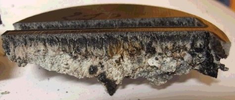
Fuel debris is a complex and quite unknown material. It is necessary to take into account spatial heterogeneities (both at macroscopic level and at the mesoscopic level of the portion of debris being cut at a given time), the presence of immiscible oxide and metal phases, of hard phases (e.g. borides), the high melting point as well as the thermal and mechanical properties of the debris. For instance, presents an in-vessel non-radioactive sample [Citation9] simulating the average best-estimate composition from unit 2 lower head estimated () within the BSAF Benchmark on the Severe Accident at Fukushima Daiichi [Citation10]. Even though it has been fabricated from a homogeneous mixture of powders, local heterogeneities such as large porosities and the presence of metallic phase balls (two of them are circled in ) are visible.
Figure 1. Laser-cut of an in-vessel simulant fuel debris [Citation9] showing heterogeneities such as porosities and metallic balls (e.g. indicated by circles).
![Figure 1. Laser-cut of an in-vessel simulant fuel debris [Citation9] showing heterogeneities such as porosities and metallic balls (e.g. indicated by circles).](/cms/asset/ad51cba6-2869-4b81-994e-d133fbbb8281/tnst_a_1462267_f0001_oc.jpg)
Table 1. Composition of lower head in-vessel simulant shown in
At a microscopic level, various different phases may be present. These phases can have quite different mechanical hardness (e.g. (U,Zr)O2 has a microhardness around 10–12 GPa, whereas borides reach 20 GPa and (Fe, Cr, Ni) can be as low as 2–4 GPa [Citation5]) or fusion temperature (steel liquidus temperature is around 1400–1500 °C whereas it can reach 2500–2800 °C for (UO2±x, ZrO2) solid solutions[Citation11] while Molten Core Concrete Interaction (MCCI) debris may have a solidification range within the 1200–2500 °C interval [Citation12] depending on the local fraction of ablated concrete in the debris). These heterogeneities may indeed complicate cutting processes.
As it is not feasible to develop and qualify the fuel debris cutting techniques on real fuel debris, these technologies need to be developed on simulants that are easy to handle with the possibility to carry out many tests while reproducing as closely as possible the expected peculiarities and difficulties of the actual fuel debris.
The most important parameters for the choice of simulants focusing on cutting capabilities are the melting temperature (for thermal cutting) and hardness (for mechanical cutting). The simulation of the material nature (ceramic, oxide) and the presence of heterogeneities must also be considered. Other material characteristics such as density, tensile strength, heat capacity, and latent heat of melt are also to be studied in order to select a simulant material.
2.1.2. Secondary outlets
Whatever the cutting technology, some secondary outlets will be generated such as aerosols (considered here as particles smaller than 10 µm), dusts (larger than 10 µm), and gases. These secondary outlets will carry significant radioactivity, which needs to be estimated and it will be necessary to collect and treat them during cutting. Indeed, Nuclear Damage compensation and decommissioning Facilitation corporation (NDF) strategic plan [Citation1] stresses the need of considering ‘the technology for gathering radioactive dust deriving from the cutting of the fuel debris and how to handle the alpha emitting particles.’
Aerosols can be generated by condensation of volatilized species, especially during thermal cutting, but also by the suspension of tiny particles generated in particular during mechanical cutting or grinding. To provide an order of magnitude, preliminary laser cutting tests [Citation13] gave mass median aerodynamic diameters between 0.2 and 0.4 µm for the simulant fuel debris shown in .
Also, as underwater cutting is a likely option, at least for the fuel debris on the pedestal and PCV floor, dissolution of fine particles that can be favored by the local high temperatures around the cutting area must also be considered.
To simulate secondary outlet generation, the chemical composition and microstructure are important parameters as well as the vapor pressures (especially for thermal cutting) and solubility in water.
Finally, interaction of hot reducing materials (zirconium alloy, molten steel, suboxidized ceramics) with steam leads to the generation of hydrogen through:
2.2. Fuel debris compositions
Fuel debris composition and nature can vary largely depending on the damaged unit and the location. All these fuel debris present heterogeneities at local and global scales such as the presence of metallic layer or metallic drops, different compositions in crusts and bulk of debris, concrete-richer plumes in uranium-richer oxidic debris [Citation12], boride grains between larger uranium oxide-rich grains [Citation7].
2.2.1. In-vessel fuel debris
The main constituents of in-vessel fuel debris will be as follows:
fuel (uranium + transuranian oxides, non-volatilized fission products);
zircalloy (mainly Zr + Sn) oxidized at a level depending on the unit accident scenario;
steel (+ activation products) coming from RPV internals and potentially ablated lower head wall;
boron carbide decomposition products.
2.2.2. Ex-vessel fuel debris
The ex-vessel fuel debris is made from the interaction of previously-described in-vessel fuel debris with:
(basaltic) concrete decomposition products (SiO2, CaO, MgO, Al2O3, …);
rebar steel;
oxygen (from concrete water content).
2.2.3. Fission and activation products and transuranians
presents the most active radionuclides, which have been calculated [Citation14] for unit 1, 10 years after the accident. The largest activities are cesium 137, barium 137, plutonium 241, yttrium 90, and strontium 90. Cesium being volatile and barium being its daughter, most of them may have been volatilized out of the fuel debris.
Figure 2. Repartition of 1F1 core radioactivity, 10 years after accident (data from [Citation14]).
![Figure 2. Repartition of 1F1 core radioactivity, 10 years after accident (data from [Citation14]).](/cms/asset/4bdc832d-78a3-4f17-a166-721c42e54e7b/tnst_a_1462267_f0002_oc.jpg)
3. Comparison of various simulant materials
A large number of simulant materials can be considered for fuel debris cutting studies: manufactured metallic or ceramic materials, combination of ceramic and metallic, solidified non-radioactive simulant melt, radioactive prototypic fuel debris. These various simulants will be described and then compared in a synthesis table ().
Table 2. Comparison of simulants
3.1. Types of simulant materials
3.1.1. Manufactured metallic or ceramic materials
From the experience in classical nuclear facility decommissioning, stainless steel is a widely studied simulant. Zirconium plates have also been studied in order to assess the release of gaseous hydrogen during underwater cutting. presents for instance a zirconium alloy plate, which has been thermally cut underwater by laser. White zirconium oxide is visible on the kerf.
Figure 3. Laser cut in a 20-mm thick Zircalloy-2 plate.
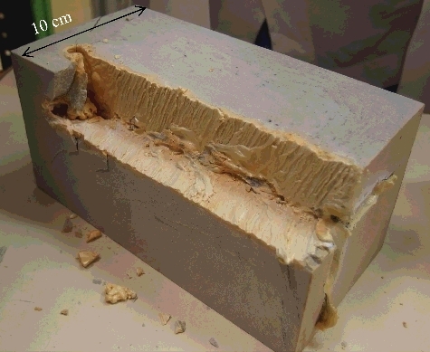
Oxide ceramics can also be used as simulant. For instance, shows a fused-cast zirconia (ZrO2) that has been selected for its fusion manufacturing process closer to fuel debris fabrication than sintering more classically used for ceramics.
Figure 4. Laser-cut fused-cast zirconia brick.
3.1.2. Combination of ceramic and metals
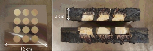
One of the anticipated difficulty of cutting fuel debris is the presence of metallic and oxidic phases, which have different behavior (both in terms of mechanical and thermal properties). Therefore, it has been sought to manufacture idealized simulants in which both types of materials are present: for instance, it can be a succession of layers of steel and ceramic plates, or a metallic plate in which ceramic pellets are embedded [Citation15], as e.g. in .
Figure 5. Metallic plate with ceramic pellets used for laser cutting and provided by IRID in the frame of the project. Left: top view before cutting. Right: side view after laser cutting.
3.1.3. Non-radioactive fuel debris simulant
A more representative simulant can be manufactured with a composition close to that which is calculated for a given sequence of the 1F accidents, in which uranium is replaced, usually mole by mole, by a surrogate element such as hafnium and plutonium and minor actinides by cerium. Hafnium has been considered as surrogate for uranium as the thermal properties of hafnium oxide (HfO2 or hafnia) and uranium oxide (UO2) are quite close [Citation16]: melting points at, respectively, 3063 and 3033 K; thermal conductivities in solid state at close to 2 W.m−1.K−1; the heat of fusions are of the order of 100 ± 30 kJ.kg−1 for both oxides; specific densities at room temperatures of 9680 and 10,500 kg.m−3.
Capriotti et al. [Citation17] have shown that ‘many similarities exist between the system Pu–O and the system Ce–O, even in the very high temperature behaviour’ and that ‘CeO2 displays…a melting behaviour which has been recently proven to be typical of other similar metal–oxygen systems such as Ca–O, Np–O and Pu–O.’ Therefore, cerium can be selected as a surrogate for plutonium and minor actinides.
For instance, such debris bed simulants including metallic and oxide phases and the presence of most fission product elements (albeit with natural isotopic vectors) have been manufactured at CEA Cadarache to test laser cutting [Citation9]. presents a view of a simulant representative of 1F2 average in-vessel lower head composition () after it has been cut by laser.
3.1.4. Prototypic fuel debris simulant
One improvement compared to non-radioactive simulant is to use depleted uranium oxide. There, the chemical composition can be reproduced, except for plutonium and other transuranians (which correspond to less than 1 wt% of the core inventory [Citation14]), whereas the isotopic composition is not. Yano et al. [Citation3] stressed that ‘before sampling from the actual reactors begins, … properties of the fuel debris should be estimated preferentially by simulated debris tests using a uranium and zirconium dioxide solid solution ….’ Both in-vessel and ex-vessel compositions and metallic and oxide phases can be reproduced in dedicated facilities (see, e.g. [Citation18]). Due to the relatively low radioactivity of depleted uranium, prototypic fuel debris simulant can be fabricated, handled, and cut in dedicated facilities outside of hot laboratories.
3.1.5. Irradiated fuel debris simulant
The closest simulant would include plutonium, minor actinides, and fission products. Such material could be produced (in small quantities) from severe accident experiments using irradiated fuel in a hot laboratory facility (see, e.g. [Citation19]). These simulants can contain all the isotopes that are expected to be found in actual fuel debris, but only small amounts of these highly radioactive materials could be synthesized. Its large radioactivity will increase the difficulties linked to the handling and cutting of irradiated fuel containing materials.
3.2. Assessment of the different materials used to simulate fuel debris
3.2.1. For cutting efficiency
For thermal cutting (laser, plasma torch…), the main properties of fuel debris are the thermal properties such as melting point, heat capacity, and thermal conductivity [Citation3]. Fuel debris porosity can also affect cutting (e.g. the ejection of molten materials before it solidifies) and must be taken into account.
For mechanical cutting (by impact, shearing, grinding), hardness, elastic modulus, and fracture toughness have been considered to be the major properties of interest [Citation20]. Local heterogeneities (porosities, different solid phases having large contrast in mechanical properties) will also affect the representability of a given simulant for mechanical cutting.
synthesizes the comparison between various types of simulant materials and fuel debris. For clarity sake, the quality has been described for the following issues (hardness, melting temperature, elastic modulus, toughness, heterogeneity, aerosol generation, gas formation – i.e. hydrogen generation, and radioactive particles) in three classes: good, meaning that all significant effects are represented; correct, meaning that there are some differences, but that the fuel debris behavior can be extrapolated from the cutting of the simulant; bad, meaning that with respect to the issue, the simulant material is not representative.
For the efficiency of mechanical cutting, it occurs that metal, industrial ceramic oxides and their mixtures, can be used as good simulant materials. For the latter, fused-cast ceramics are preferred to sintered ceramics as their manufacturing process is closer to the fabrication process of fuel debris, which are mainly created from molten materials. Nevertheless, the effects of material heterogeneities (porosities, metal/oxide phases, boride inclusions, …) that can lead to sharp variations in response to the cutting tool cannot be reproduced by such simulants.
The elastic modulus of uranium dioxide lies in the 150–200 GPa range [Citation21], which is of the same order than that of zirconia (90–200 GPa), alumina (100–300 GPa), or hafnia (100–200 GPa) ceramics. Concerning hardness, Takano et al. [Citation22] have indicated that the microhardness of stainless steel constituents (Fe–Cr–Ni) was between 2 and 10 GPa, 4 GPa for intermetallics such as (Fe,Cr,Ni)2 (U,Zr) while solidified (U,Zr)O2 melt microhardness lies between 10 and 12 GPa, and that of borides (such as (Fe,Cr,Ni)2B and ZrB2) lies between 15 and 20 GPa. Hafnium oxide hardness has been reported in the 8–10 GPa range [Citation23] close to that of uranium–zirconium oxides. Concerning fracture toughness, Hoshino et al. [Citation20] report values around 1 MPa.m1/2 for UO2 and 7 MPa.m1/2 for ZrO2 while for UO2±x containing up to 60-mol% ZrO2, as expected in severe accident fuel debris, this value remains below 2 ± 0.5 MPa.m1/2.
From these data, it is clear that borides, which have a large hardness may affect mechanical cutting. Moreover, zirconium dioxide (or hafnium dioxide, the properties of which are close to those of zirconium dioxide) will be tougher than uranium dioxide containing fuel debris.
Regarding thermal cutting, zirconium dioxide and hafnium oxides are often used as simulant materials for uranium dioxide. For HfO2, main advantages are a high density of dioxide (9.68 for HfO2 vs. 10.5 for UO2 and 5.68/6.10 for monoclinic and tetragonal ZrO2 at room temperature [Citation16]) and a high melting point (3063 K vs. 3033 K [Citation16]) with a difference lower than the measurement uncertainties at these high temperatures. The specific heats are also of the same order of magnitude (around 300 J.g−1.K−1 between room temperature and melting). Thermal conductivities of hafnium dioxide, zirconium dioxide, and uranium dioxide are of the same order (around 2 W.m−1.K−1) in the solid range.
Emissivity is an important parameter for laser cutting, especially in the near-infrared (close to the 1.06-µm wavelength of the YAG lasers used for cutting). Unfortunately, we have not found any reported data on the emissivity at the 1.03-µm wavelength for the materials of interest. Zirconium dioxide emissivity in the near-infrared seems to be close to the normal total emissivity and is quite low (∼0.3) at low to medium temperatures, but becomes higher than 0.7 above 2000 K [Citation24]. Concerning hafnium oxide, there are few data in the literature. The spectral emissivity is only reported at 0.65 µm and remains between 0.71 and 0.81 from 1900 to 2300 °C [Citation25]. The normal total emissivity also remains in the 0.79–0.93 range between 1000 and 2300 °C. Except for the lower temperatures, we can consider from available data that zirconia and hafnia have similar emissivities above 1800 °C.
For premelted UO2, the normal spectral emissivity (at 0.63 µm) stays between 0.82 and 0.84 between room temperature and melting point [Citation26]. Reported values for liquid urania are between 0.84 and 0.91. Concerning the total emissivity, Fink and Petri [Citation26] recommended using the constant value of 0.85.
It appears thus that, at high temperatures, zirconium and hafnium dioxides will have slightly lower emissivity than uranium dioxide. Tests with simulant materials will therefore be conservative with respect to laser cutting and could be used as simulant in the definition of fuel debris samples.
Optical transmission at the laser wavelength is finally an important parameter. Fuel debris is opaque in the near-infrared and thus semitransparent oxides (such as SiO2 and Al2O3) will behave in a different way with respect to lasers.
3.2.2. For secondary outlet (particles) generation
Part of the dust and fumes due to cutting are made from small grains that are ejected from the solid material during cutting. They are thus closely linked to the solid phase microstructure. There are nevertheless limitations with the use of non-radioactive simulants. They are mainly due to the very peculiar chemical characteristics of uranium, which has four oxidation states leading to the possible presence in the U–O system of U, UO, UO2±x, U4O9, U3O7, U2O5, U3O8, and UO3 solid phases [Citation27]. Moreover, the solubility of fission products in these phases is not fully modeled (see, e.g. [Citation28]), so it is difficult to find a surrogate oxide that could be used to estimate the extent and radioactivity of dust and fumes that would be ejected from fuel debris.
For thermal cutting, the major source of aerosols () is assumed to come from the evaporation and subsequent condensation of the species remaining in the fuel debris when it is locally melted. Due to the presence of many gaseous phases in the U–O system (U, UO, UO2, UO3, and O2), the O/U ratio can evolve with temperature, thanks to the release of gaseous UO or UO3 [Citation29]. Similar phenomena cannot be found with simulant materials. For instance, the thermodynamic calculations reported in Appendix for an in-vessel composition and its simulation with hafnium replacing mole-by-mole uranium shows that uranium will be much more abundant in the aerosols than hafnium and will represent the largest radioactive element in these outlets. Nevertheless, these results should be experimentally confirmed.
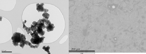
Figure 6. Scanning electron microscope view of a typical aerosol cluster (left) and from larger size aerosols (right) collected during the laser cutting in air of the in-vessel fuel debris simulant block defined in and shown in .
Therefore, the use of prototypic simulant appears to be necessary to study the aerosol generation during thermal cutting as no natural element can reproduce the volatiles in the uranium–oxygen system.
3.2.3. For secondary outlet (combustible gas) generation
As the most rapid generation of combustible gas may occur from the steam oxidation of zirconium leading to the generation of hydrogen, zirconium (or zirconium alloy) plates can be used as a means to obtain conservative estimates of the hydrogen generation. For instance, laser cutting tests have been conducted at CEA Saclay with 10 mm- to 30-mm thick Zircalloy-2 plates. The release of hydrogen leads to concentrations up to 0.4 vol.% H2, which would correspond to the oxidation of less than half the metal that has been heated above 1200 °C.
Other tests with the fuel debris simulant shown in lead to lower generation of hydrogen (0.04 vol.%). It is not expected that the presence of uranium would significantly affect those results; therefore, non-radioactive simulants are considered to be valid for this issue.
4. Example of laser cutting of various simulants
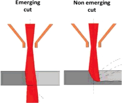
Laser cutting experiments have been conducted at CEA Saclay in view of developing a technology that can be applied to fuel debris retrieval at Fukushima Daiichi. These experiments have been carried out with various types of simulant at DELIA facility [Citation8] dedicated to in-air and underwater laser cutting. This facility () includes a laser source (TRUMPF continuous wave Nd:YAG laser with a rated power of 8 kW at 1.03-µm wavelength), a cutting cell (4-m3 steel cylinder), and a test section including a 5-m high chimney in which aerosols can be sampled for analysis [Citation13]. Details on the laser head and on the application to stainless steel cutting have previously been described by Chagnot et al. [Citation30]. A flushing air jet surrounds the laser beam and evacuates the molten material generated by laser heating. Two configurations have been tested: emerging and non-emerging cuts (), which mainly differ by the path available for the ejection of molten material. For underwater cutting, a nozzle creates a dry area around the laser beam in order to maintain the laser fluence on the material to be cut.
Figure 7. View of DELIA ∅1.38-m test section with vertical laser head and inactive fuel debris simulant.
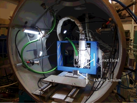
Figure 8. Scheme of the emerging and non-emerging cutting configurations.
4.1. Cutting of manufactured ceramic or metallic materials
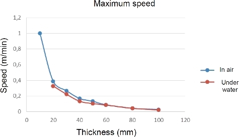
Laser cutting of fused-cast zirconia () has been largely used to optimize laser cutting configurations. For instance, summarizes the maximum cutting speed that has been determined for non-emerging laser cutting of fused-cast zirconia. The values are almost equivalent in air and under 17 cm of water. With small cutting speeds, depths of ceramic up to 10 cm can be cut at 2.4 cm/min. Under 5.6 m of water, only 4 cm of zirconia could be cut at 12 cm/min or 5 cm at 1 cm/min.
Figure 9. Maximum laser-cutting speed achieved for various thicknesses of zirconia bricks.
Metallic blocks have also been considered. The results of Chagnot et al. [Citation30] on stainless steel have been confirmed. Emerging and non-emerging laser cuts of Zircalloy-2 blocks have also been successfully carried out (), although the maximum achievable speeds are lower than those observed for zirconia; this may be because of the oxidation of the slag. Zircalloy 2, which was 3-cm thick, has been cut at 5 cm/min under 5.6 m of water, creating a hydrogen concentration of less than 0.15 vol.%.
Then, a specific sample made of ceramic pellets in a steel plate () has also been studied. Data have been obtained during the cutting of this sample, provided by International Research Institute for Nuclear Decommissioning (IRID), using the laser power of 8 kW in four different configurations: emerging and non-emerging cuts in air, and emerging and non-emerging cuts under water.
Calculated value includes the slag that remains attached to the sample after cutting as well as the oxygen gained during oxidation reactions. In air, mass flow rate is greater than 70 g/min; under water, it is greater than 50 g/min for the emerging cut. The performance for a non-emerging cut under water is lower. Work is underway to optimize the underwater head for emerging cutting configuration.
Tests have shown that the type of material does not have a significant impact on process performance for electrocast zirconium oxide (ZrO2), 316 L stainless steel, or ‘IRID’ hybrid samples, as the potential effects of alumina (Al2O3) fragmentation are limited by the metal matrix.
It should be recalled that tested processes, developed by CEA, are optimized for other conditions and objectives, namely to cut thick pieces in a single pass. For emerging cut, thicknesses are typically 100 mm in air and 50 mm under water. For non-emerging cutting, developed process allows to extract blocks with a 25 × 25 mm² section by making two cross-cuts at 90°, each performed at a speed of 15 cm.min−1. In this case, the volume flow rate is three times higher and close to 47 cm3.min−1 (2.5 cm × 2.5 cm × 15 cm.min−1 for two cuts).
4.2. Inactive fuel debris simulant
Two simulant blocks have been manufactured at CEA Cadarache: one simulating an in-vessel fuel debris composition ( and ) and one representing an ex-vessel MCCI debris [Citation9].
The in-vessel debris simulant has been cut with the 8-kW laser moving at a feed rate of 6 cm.min−1 for a kerf depth of 30 mm and a 2-mm width. Similarly, the ex-vessel MCCI simulant has been cut to a depth of 50 mm with a feed rate of 3 cm.min−1. Similar experiments have been achieved underwater on these simulants.
Aerosols and dross have been collected during these cutting tests. Mass median diameters of the order of 200 nm have been determined [Citation13] for the in-air cutting of these two inactive simulants. Underwater, larger median diameters (around 400 nm) have been observed; underwater conditions are assumed to be more favorable to agglomeration than dry ones. presents typical aerosol shapes close to the median size and at larger diameters. It appears that submicronic aerosols carry most of the aerosol mass and form clusters that have a fractal morphology. Fractal dimensions around 1.8, similar to that of combustion soot, have been measured [Citation13]. At larger sizes, there are fewer particles and they have a quite spherical shape.
5. Conclusion
The relative merits of the various types of materials (stainless steel, zirconium, sintered alumina/zirconia, cast-fused zirconia, metal + ceramic, melted inactive simulants, prototypic fuel debris simulant, irradiated fuel debris simulant) that can be used to simulate fuel debris cutting have been assessed against criteria relevant for the cutting technique itself (hardness, melting temperature, elastic modulus, toughness, heterogeneity) as well as relevant to (radioactive) aerosol and combustible gas generation ().
It appears that simplified simulants such as steel, zirconium or fused-cast zirconia plates can be used for the development of fuel debris cutting techniques, but have some limitations in terms of representativeness so that melted inactive fuel debris simulant must be used to assess the cutting performance. For thermal cutting, replacement of uranium by hafnium and plutonium by cerium provides a satisfactory representativeness while other compositions may be better suited for mechanical cutting.
Concerning combustible gas generation, zirconium plates will provide an upper bound in terms of underwater generation of hydrogen. Finally, for aerosol and dust generation, it appears that any non-radioactive simulant without uranium cannot correctly represent the aerosol formation during cutting. Prototypic fuel debris simulant, using depleted uranium, natural isotopic composition for the fission product elements and cerium as a surrogate of plutonium are the best available options for determination of cutting secondary outlet.
Laser cutting tests have been conducted in the DELIA facility at CEA Saclay with several types of simulant materials (stainless steel, fused-cast zirconia, Zircalloy-2, steel + ceramic object, inactive in-vessel and ex-vessel fuel debris simulants). Promising results have been achieved in term of cutting ability both in air and underwater. Data have also been collected on the released aerosols. Nevertheless, confirmatory experiments are still necessary with prototypic fuel debris, in particular with respect to the dust and fume issues.
Acknowledgments
This work has been carried out thanks to the subsidized project of Decommissioning and Contaminated Water Management (Advancement of Fundamental Technologies for Retrieval of Fuel Debris and Internal Structures) funded by the Japanese Ministry of Economy, Trade and Industry (METI) and managed by the Mitsubishi Research Institute (MRI).
Disclosure statement
No potential conflict of interest was reported by the authors.
Additional information
Funding
Notes
1. A prototypic mixture has the same chemical composition as the real corium, but a different isotopic composition: in practice, depleted uranium is used instead of enriched uranium, and stable natural isotopic composition is used to simulate the radioactive fission product elements.
Related Research Data
References
- NDF. Technical strategic plan 2017 for decommissioning of the Fukushima Daiichi Nuclear Power Station of Tokyo Electric Power Company Holdings, Inc. Tokyo: Nuclear Damage Compensation and Decommissioning Facilitation Corporation; 2017.
- Tezuka M. Nakamura Y, Iwai H, et al. The development of thermal and mechanical cutting technology for the dismantlement of the internal core of Fukushima Daiichi NPS. J Nucl Sci Technol. 2014;51:1054–1058.
- Yano K, Kitagaki T, Ikeuchi, H, et al. Direction on characterization of fuel debris for defueling process in Fukushima Daiichi Nuclear Power Station. Proceedings of GLOBAL 2013: International Nuclear Fuel Cycle Conference; 2013 Sep 29–Oct 3; Salt Lake City, UT.
- Falk DE, Swenson CE. TMI-2 defueling system design description. Madison (PA): Westinghouse Electric Co.; 1985. ( Report GEND-INF-065).
- Takano M, Nishi T, Shirasu N. Characterization of solidified melt among materials of UO2 fuel and B4C control blade. J Nucl Sci Technol. 2014;51:859–875.
- Ikeuchi H, Piluso P, Fouquart P, et al. Study on the distribution of boron in the in-vessel fuel debris in conditions close to Fukushima Daiichi Nuclear Power Station Unit 2. Proceedings of ERMSAR-2017 (European Review Meeting on Severe Accident Research); 2017 May 16–18; Warsaw (Poland).
- Kitagaki T, Yano K, Ogino H, et al. Thermodynamic evaluation of the solidification phase of molten core–concrete under estimated Fukushima Daiichi nuclear power plant accident conditions. J Nucl Mater. 2017;486:206–215.
- George, C, Roulet, D, Chagnot C, et al. Benefits from developments in the field of Decommissioning for Fukushima Daiichi fuel debris retrieval: Remote-Controlled Laser Cutting Process. Proceedings of 43rd Annual Waste Management Conference (WM2017), Published by WM Symposia, Tempe AZ, 2017.; 2017 Mar 6–9; Phoenix, AZ.
- Journeau C, Monneris J, Tormos B, et al. Fabricating Fukushima Daiichi in-vessel and ex-vessel fuel debris simulants for the development and qualification of laser cutting technique. Proceedings of ERMSAR-2017 (European Review Meeting on Severe Accident Research); 2017 May 16–18; Warsaw (Poland).
- Pellegrini M, Dolganov K, Herranz Puebla LE, et al. Benchmark study of the accident at the Fukushima Daiichi NPS best estimate case comparison. Proceedings of NURETH- 16, August 30-Sept 4, 2015, American Nuclear Society (ANS), LaGrange Park IL; 2015 Sep; Chicago, IL.
- Mastromarino S, Seibert A, Hashem E, et al. Assessment of solid/liquid equilibria in the (U, Zr)O2+y system. J Nucl Mater. 2017;494:368–379.
- Journeau C, Piluso P. Core concrete interaction. In: Konings RJM, editor. Comprehensive nuclear materials. Vol. 2. Amsterdam: Elsevier; 2012. p. 635–654.
- Porcheron E, Peillon S, Gelain T, et al. Analysis of aerosol emission and dispersion during the laser cutting of Fukushima fuel debris simulants. Proceedings of ICONE-26, July 22-28, 2018; 2018; London (United Kingdom); New York City: ASME.
- Nishihara K, Iwamoto H, Suyama K. Estimation of fuel compositions in Fukushima-Daiichi Nuclear Power Plant. 2012. ( JAEA Report JAEA-Data/Code 2012-018); Tokai-mura: JAEA (Japan Atomic Energy Agency).
- Nomura K, Shiihara K, Chida I, et al. Evaluation of removal technologies of fuel debris using the laser processing. Proceedings of the 20th National Symposium on Power and Energy Systems (SPES 2015), 18-19 June 2015, Power and Energy System Division of Japan Society of Mechanical Engineers (JSME); 2015 Jun; Tokyo (Japan); 2015.
- Samsonov GV. The oxide handbook. New York (NY): IFI/PLENUM; 1973.
- Capriotti L, Quaini A, Böhler R, et al. A laser heating study of CeO2 solid/liquid transition: challenges related to a refractory compound with a very high oxygen pressure. High Temp High Press. 2014;44:69–82.
- Bouyer V, Cassiaut-Louis N, Fouquart P, et al. PLINIUS prototypic corium experimental platform: major results and future works.Proceedings of NURETH-16, August 30-Sept 4, 2015, Chicago IL. American Nuclear Society (ANS), LaGrange Park IL. 2015.
- Geiger E, Le Gall C, Gallais-Duraing A, et al. Fission products and nuclear fuel behaviour under severe accident conditions part 2: fuel behaviour in the VERDON-1 sample. J Nucl Mater. 2017;495:49–57.
- Hoshino T, Kitagaki T, Yano K, et al. Mechanical properties of fuel debris for defueling towards decommissioning. Proceedings of ICONE-23, May 17-21, 2015. Japan Society of Mechanical Engineers (JSME), Tokyo; 2015 May; Chiba (Japan).
- NIST structural ceramics database (SCD) database [internet]. National Institute of Standard and Technologies; [consulted 2017 Oct 27]. 2015; Gaitherburg MD. Available from: https://srdata.nist.gov/CeramicDataPortal/scd
- Takano M, Nishi T, Shirasu N. Characterization of solidified melt around materials of UO2 fuel and control blade. J Nucl Sci Technol. 2014;51:859–875.
- Berdova M, Liu X. Hardness, elastic modulus, and wear resistance of hafnium oxide-based films grown by atomic layer deposition. J Vacuum Sci Technol A. 2016;34:051510.
- Cognet G, Journeau C, Jégou C. Infrared thermography for measuring the surface temperature of a zirconia melt. Proceedings of the International Symposium on Radiative Heat Transfer, 14-18 August 1995. International Center for Heat and Mass transfer (ICHMT), Begell House, Danbury CT; 1995; Kusadasi (Turkey).
- Sala A. Radiant properties of materials. Amsterdam: Elsevier; 1986.
- Fink JK, Petri MC. Thermophysical properties of uranium dioxide. Argonne, IL: Argonne National Laboratory. 1997. ( Argonne National Laboratory report ANL/RE-97/2).
- Grenthe I, Drożdżyński J, Fujino T, et al. Uranium, in the chemistry of the actinide and transactinide elements. Dordrecht: Springer; 2008. p. 253–698.
- Geiger E, Bès R, Martin P, et al. Insights on fission products behavior in nuclear severe accident conditions by X-ray absorption spectroscopy. J Nucl Mater. 2016;471:25–33.
- Edwards RK, Chandrasekharaiah MS, Danielson PM. The congruently evaporating composition of Urania. High Temp Sci. 1969;1:98–113.
- Chagnot C, de Dinechin G, Canneau G. Cutting performances with new industrial continuous wave Nd:YAG high power lasers for dismantling of former nuclear workshops: the pertinence of newly introduced continuous wave Nd:YAG lasers are assessed. Nucl Eng Des. 2001;240:2604–2613.
Appendix.
Thermodynamic calculations of gaseous releases over fuel debris and its simulant
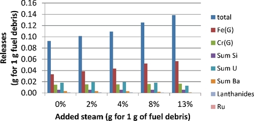
Thermodynamic calculations have been carried out with the NUCLEA10 database and GEMINI2 on VF04 in-vessel fuel debris simulant [Citation9] theoretical composition () to which various quantities of steam has been added. In these calculations, only boron, barium, carbon, chromium, iron, hydrogen, lanthanum, nickel, oxygen, ruthenium, silicon, uranium, and zirconium are present, both in the debris and the database. Rare earths are modeled by lanthanum, tellurium is modeled by silver, and hafnium is represented by zirconium as these elements have close chemical properties. Mole-by-mole replacement of elements by their surrogates has been considered.
Table A1. Compositions used for the thermodynamic calculations above volatilized species from fuel debris and simulant (masses for 100 g of solid material)
presents the estimated vapor masses at 2950 K over this molten fuel debris, considering steam content in a neutral atmosphere (modeled here by 50 g of argon added to 100 g of fuel debris). There is a clear increase of the vaporized mass with steam content. The major vapors are iron (Fe), chromium (Cr), silicon (mainly SiO, and to a lesser extent Si), uranium vapors (mainly UO, but also in decreasing order UO2, U, and UO3), barium (Ba and to a lesser extent BaO and BaBO2), and lanthanides (mostly as monoxides). The last three elements bear most of the radioactivity.
Figure A1. Calculated gaseous releases for in-vessel composition (modeling composition).
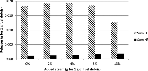
Similar calculations have been made for a simulant composition in which the hafnium simulant is replaced mole-by-mole by zirconium and compared to those from previous calculations with uranium. shows that there are 7–15 times more uranium-bearing gaseous releases compared to those of hafnium (mainly HfO2 with some Hf and traces of HZr).
Figure A2. Comparison of uranium volatiles and hafnium volatiles for the in-vessel fuel debris (respectively, simulant) for various steam contents.
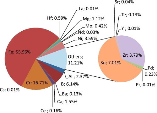
As there were 0.6 wt% hafnium in the collected inactive aerosols from underwater cutting tests with simulant (), and lower values during curing in air. Moreover, hafnium releases were significantly lower than those of zirconium (0.6% vs. 3.8 wt%) whereas the mass concentration of hafnium was about half (57%) of that of zirconium in the cut block. This is assumed to be due to the higher boiling point of hafnium (not taken into account in the modeling).
Figure A3. Average composition of the aerosols collected from laser cutting underwater of the in-vessel fuel debris simulant shown in (simulant block composition in ).
Uranium is thus expected to be more abundant than hafnium (4 to 25 wt% depending on the assumptions), thus, by far, the most abundant radioactive element in the generated aerosols. Moreover, such a large presence of uranium in the vapors and the aerosols can have a noticeable effect on the releases of other species.
Nevertheless, it would be advisable to have experimental validation of these calculation results to assess the actual amount of uranium aerosols and its global effects on the aerosol chemistry.