 ?Mathematical formulae have been encoded as MathML and are displayed in this HTML version using MathJax in order to improve their display. Uncheck the box to turn MathJax off. This feature requires Javascript. Click on a formula to zoom.
ABSTRACT
Frequent beam trips as experienced in existing high-power proton accelerators may cause thermal fatigue in Accelerator-Driven System components. In order to overcome the beam-trip problem, the beam-trip frequencies were estimated based on operational data on existing accelerators. However, there are at least three methods to calculate the mean time between accidental interruptions (MTBI) for one of the accelerator components, the klystron system. In this study, the four types of MTBI for the klystron systems of an electron/positron injector linear accelerator at the High Energy Accelerator Research Organization were compared based on the same operational data. In the analysis, the stop events of the klystron systems were classified, and the MTBI for the klystron systems was calculated using the Kaplan–Meier (KM) estimation, which is a representative non-parametric reliability method. As a result, the mean value of the MTBI found by the KM estimation was 57.3 ± 6.5 hours. On the other hand, the mean values of the MTBI found by the three traditional methods were 30.9 ± 2.4, 32.0 ± 2.3, and 50.4 ± 5.9 hours. The mean values for the ratios of the MTBI found by the KM estimation, to the MTBI found by the traditional estimation, were 1.67 ± 0.07, 1.58 ± 0.06, and 1.14 ± 0.01, respectively. Although these results are obviously different from traditional results, it appears that the present estimation is suitable for the MTBI for accelerator components.
1. Introduction
The Japan Atomic Energy Agency (JAEA) promotes research and development (R&D) into the Accelerator-Driven System (ADS), which reduces the burden of conditioning and disposal of high-level radioactive waste by transmuting minor actinides. The proposed ADS [Citation1,Citation2] is operated using the spallation neutrons generated by a high-power proton linear accelerator (linac). Since the ADS is a hybrid system of the linac and a sub-critical nuclear reactor, there are various R&D issues inherent to ADS. The beam-trip problem has been pointed out as one of the critical issues. Experiences with existing high-power proton accelerators indicate that frequent beam trips are inevitable. As beam trips may cause thermal fatigue in ADS components, which may lead to degradation of their structural integrity and a reduction in their lifetime, it is important to reduce the beam-trip frequency of high-power proton accelerators to an acceptable level.
In order to overcome the beam-trip problem, JAEA has examined the concept of the accelerator for JAEA's reference ADS by means of the following steps:
evaluating the acceptable beam-trip frequency based on the structural requirements of the ADS component,
estimating the beam-trip frequency caused by the accelerator for JAEA's reference ADS based on operational data on existing accelerators, and
discussion of the mechanical method to reduce the beam-trip frequency.
In general, beam trips are caused by the use of a Machine Protection System (MPS) to protect accelerators against failure. The reasons for activating the MPS can be classified into two broad categories: one is the failure and/or the repair/replacement of accelerator components, and the other is accidental interruption to protect accelerators against fatal failures. In the former case, the preliminary estimated beam-trip frequency for the proton accelerator of JAEA's reference ADS was about 0.17 times per hour, based on a credible and validated database of reliability figures for accelerator components such as Mean Time Between Failures (MTBF) [Citation2]. On the other hand, in the latter case, the beam-trip frequency for the proton accelerator has not been predicted so far, because a component database of reliability figures such as MTBI has not yet been established. A principal reason this component database does not exist is the inconsistency of data collection and analysis methods among laboratories [Citation4].
As mentioned previously, there are at least three methods to calculate MTBI for the klystron systems which are components of the radio-frequency (RF) system used with the linac, where MTBI is the total length of the operation time divided by the total number of stop events. (Details are presented in Section 4.1) These estimation methods have not been unified into one. There are two main reasons that no unified method has yet been developed:
| (1) | Operational data might be collected with no distinction between accidental interruptions in the klystron system and the termination of normal operation of the klystron system by its operators, for example regular maintenance. Also, the MTBI might be calculated with no distinction between the two. | ||||
| (2) | Accidental interruptions for the klystron system were assumed to occur randomly, namely, the probability density function of accidental interruptions for the klystron system was assumed to have an exponential distribution. | ||||
In general, however, the lifetime test was performed on many products under fixed conditions [Citation5]. As for the data collection approach, the elapsed time from start to failure was recorded for each dead product. On the other hand, the elapsed time from start to censoring, i.e. the ending of the test window, was recorded for each surviving product. As for the data analysis approach, the lifetime to failure was evaluated by use of non-parametric methods to assume no underlying distribution for the probability density function of failure. Hereafter, the ‘reliability engineering method’ refers to the method to satisfy these conditions of the data collection and analysis approach for the lifetime test. Examples of the application of the reliability engineering method are available in the form of lifetime estimations for various systems used in space satellites orbiting the earth [Citation6].
As detailed operational data on the accelerator components has been obtained, the purpose of this study is to evaluate and compare the four types of MTBI based on the same operational data. This comparison seemed to be valid to build the component database of reliability figures using the unified data collection and analysis method. To achieve this purpose, this article consists of the following items:
Classification of stop events of klystron systems based on detailed operation data obtained from an electron/positron injector linac [Citation7] at the High Energy Accelerator Research Organization (KEK) such as accidental interruptions and censored events.
Calculation of the MTBI for the klystron systems by use of a non-parametric method.
Discussion of differences between the MTBI found by the reliability engineering method and the MTBI found by traditional methods.
After describing some definitions and useful acronyms in Section 2, an overview of the electron/positron injector linac at KEK and operational data is presented in Section 3. In Section 4, the MTBI for the klystron systems is calculated based on detailed operational data. Finally, we make a comparison between the MTBI obtained using the reliability engineering method and that found by the traditional methods in Section 5.
2. Some definitions and useful acronyms
Let us review some words that will be used extensively in this article.
The ‘electron/positron injector linac at KEK’ is abbreviated to the ‘KEK injector linac.’
The ‘klystron system’ is defined as the assembly of the klystron, its relevant system (e.g. RF excitation system, electric power supply, and so on) and the waveguide.
The ‘subsystem’ is referred to as the klystron system.
The ‘RF system’ is defined as the assembly of the klystron systems.
‘Censored event’ is defined as the event where the normal operation of the klystron system is terminated manually by its operators for regular maintenance, or due to a deactivation request from systems other than the klystron system, and so on. Details are presented in Section 3.2.
‘Stop event’ is a general term applied to both accidental interruption and a censored event.
‘Operation time’ of the klystron system is defined as the elapsed time from the beginning of the operation to the termination.
‘Down time’ of the klystron system is defined as the elapsed time from the termination of the operation to the restart.
‘MTBI’ is defined as an average operation time of the klystron system.
‘Accidental interruption rate’ is defined as the number of accidental interruptions in unit time.
3. KEK injector linac
3.1. General scheme
The KEK injector linac [Citation7] is capable of providing electrons at energies up to 8 GeV and positrons up to 3.5 GeV, and is used as a multi-purpose injector not only for KEK B-Factory (KEKB), but also for Photon Factory (PF). At present, it delivers full-energy beams of 8-GeV electrons to the KEKB high-energy ring and 3.5-GeV positrons to the KEKB low-energy ring. The linac was originally constructed as a 2.5-GeV injector for the PF in 1982. However, this old linac was extensively reconstructed for the B-Factory project during 1994–1998 [Citation8]. The whole linac consists of 55 S-band (2856 MHz) main accelerator modules. Fifty MW pulse klystrons with a time duty factor of 0.02% were developed in conjunction with the energy upgrade of the linac for the B-Factory project. These tubes were designed to be compatible with the old version of the 30 MW tubes in that the major dimension of the new tube was not changed.
In order to operate the linac stably, RF monitoring systems for power level and phase were installed in all high-power klystrons and are controlled with a VMEbus eXtensions for Instrumentation based controller. Each klystron is controlled with a programmable logic controller based controller, which monitors the interlock status and vacuum status, and also provides a historical record of the operational data. To protect the RF window from failure, the klystron operations are terminated by a voltage standing wave ratio interlock, which trips over the limiting value of 1.4. Operations are automatically restarted after 5 seconds.
3.2. Operational data
The total operation time of the KEK injector linac reached over 120000 hours from Japanese Fiscal Year (JFY) 1982 through JFY 2005. In this study, statistics on interruptions and the down time distribution of the RF system were obtained from operational data in JFY 2005. The scheduled beam time was 6815 hours, the long-term maintenance time for summer and New Year holiday season was 1703 hours, and time for regular maintenance every two weeks was 242 hours in total.
As not all the klystron systems were used in the normal operation of the KEK injector linac, we selected 57 klystron systems from all the 60 klystron systems under the condition that the total length of the operation time for the klystron system in JFY 2005 was close to the scheduled beam time. The total number of stop events for 57 klystron systems was 16059. To decide whether the stop event corresponded to the censored event or not, first, we determined the conditions for the censored event. Four categories for the censored event were established as follows:
| A. | manual interruptions for long-term maintenance in the summer and New Year holiday season, | ||||
| B. | manual interruptions for regular maintenance every two weeks, | ||||
| C. | deactivation requests from systems other than the klystron system, and | ||||
| D. | ending of our observation window (March 2006). | ||||
The number of censored events which corresponded to these categories was 2909, and the breakdown of the total was: 106 for category A, 872 for B, 1882 for C, and 49 for D. Almost all interruptions belonging to category C were manual terminations in order to regulate equipment located in the accelerator tunnel. Operational data of the klystron systems were random censoring data that were right-censoring with staggered entry. This means the following: (Equation1(1)
(1) ) klystron systems were activated at different points in time, (Equation2
(2)
(2) ) dates for accidental interruptions and censoring were stochastic, and (Equation3
(3)
(3) ) censoring occurred because klystron systems were still operational at the end of our observation window.
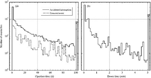
(a) shows the distribution of the operation time between the interruptions. The solid histogram represents the operation time for accidental interruptions. On the other hand, the dotted histogram represents that for censored events. The gray right arrow in (a) shows that the last bin is the sum of all interruptions of not less than 100 hours. The maximum operation times for accidental interruptions and for censored events were 531 and 495 hours, respectively, and the simple mean values of the operation time for accidental interruptions and for censored events were 20.5 and 36.0 hours, respectively. (b) shows the number of accidental interruptions as a function of the down time. The gray right arrow in (b) shows that the last bin is the sum of accidental interruptions of not less than five minutes. The simple mean value of the down time for the accidental interruption was 256 seconds.
Figure 1. Distribution of (a) the operation time for accidental interruptions and censored events, and (b) the down time for accidental interruptions.
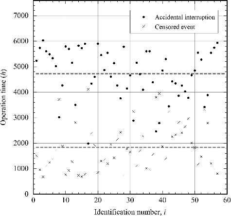
shows the total length of the operation time ending in accidental interruptions and censored events (hereafter referred to as Ti and T#i, respectively) as a function of the identification number of the klystron system, which is represented as i (= 1,… , 57). Here, the identification numbers of the klystron system i run from the electron-gun side, that is, from the upstream to the downstream. Gray dashed lines in this figure represent simple mean values for Ti and T#i, which are 4725 and 1837 hours, respectively.
Figure 2. Total length of the operation time ending in accidental interruptions and censored events as a function of the identification number of the klystron system. Gray dashed lines represent simple mean values for Tiand T#i.
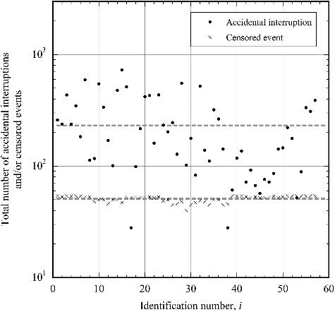
shows the total number of accidental interruptions and censored events (hereafter referred to as ni and n#i, respectively) as a function of the identification number of the klystron system. Similarly, gray dashed lines represent simple mean values for ni and n#i, which are 231 and 51, respectively. The principal reasons why the total number of censored events differed were: (Equation1(1)
(1) ) some klystron systems were partially interrupted by deactivation requests and (Equation2
(2)
(2) ) a maintenance operation was started before the suspended klystron system was operated.
Figure 3. Total number of accidental interruptions and censored events as a function of the identification number of the klystron system. Gray dashed lines represent simple mean values for niand n#i.
Data points determined by the abscissa and the ordinate
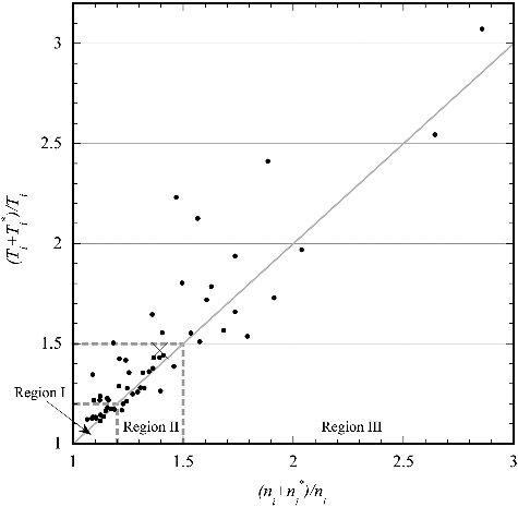
for the ith klystron system are plotted as shown in . The large cross-mark in this figure represents simple mean values for these data points. Thirty-eight data points out of 57 exist in the range of both coordinate values which were 1.5 or less. On the other hand, both coordinate values for some data points were almost three. As shown by the gray dashed lines in , we divided the data into the following three regions.
(1)
(1)
(2)
(2)
(3)
(3)
The number of klystron systems for each region was 12, 26, and 19, respectively. To compare the data points existing in Region I to those in III, the ratio of censored events to stop events was increased in the latter case.
4. MTBI evaluation of the klystron system
In order to compare the MTBI for the klystron systems using the reliability engineering method with that found by the traditional methods, several types of MTBI for each klystron system are defined in this section.
It should be noted that the MTBI was first obtained for each klystron system and then these values were averaged by considering MTBI's differences in the klystron systems. On the other hand, the MTBI can also be evaluated when looking at an RF system comprising an assembly of the klystron systems as subsystems. Details are presented in Appendix 1.
Unless otherwise noted, statistical calculations such as the error estimation, the approximation, and so on were conducted using the survival time analysis provided by the JMP statistical packages [Citation9].
4.1. Ordinary methods
Although there are at least three methods to calculate the MTBI, a common feature of the three methods is that they are derived from the relationship between the total length of the operation time and the total number of interruptions. Details for the three methods are as follows.
Method 1:
the MTBI λ1i for the ith klystron system is calculated as the total length of the operation time ending in accidental interruptions divided by the total number of accidental interruptions, that is
(4)
(4)
Method 2:
the MTBI λ2i for the ith klystron system is calculated as the total length of the operation time ending in accidental interruptions and censored events divided by the total number of accidental interruptions and censored events, that is
(5)
(5)
Method 3:
the MTBI λ3i for the ith klystron system is calculated as the total length of the operation time ending in accidental interruptions and censored events divided by the total number of accidental interruptions, that is
(6)
(6)
The features of these methods were as follows:
Method 1: the MTBI was a simple mean value for the operation time ending in accidental interruptions, and the operation times ending in censored events were not included in the calculation.
Method 2: the MTBI was a simple mean value for the operation time ending in accidental interruptions and censored events, and no distinction between the accidental interruption and the censored event was made.
Method 3: accidental interruptions were assumed to occur randomly, i.e. the probability density function of accidental interruptions for the klystron system was assumed to have an exponential distribution [Citation5]. In this case, the accidental interruption rate was constant with the operational time, and was judged to be the inverse of the MTBI [Citation5].
Using EquationEquations (4)(4)
(4) and (Equation5
(5)
(5) ), EquationEquation (6)
(6)
(6) may also be written in the alternative form:
(7)
(7)
Therefore, EquationEquation (8)(8)
(8) obviously holds:
(8)
(8)
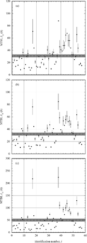
shows the three types of MTBI as a function of the identification number of the klystron system. The error bar in each figure represents a standard error (±1σ, the same applies hereafter) of the MTBI. The dashed line in each figure represents the simple mean value of the MTBI for the klystron systems. The gray rectangle centered on the dashed line represents the range within a standard error of the simple mean value. The mean values are 30.9 ± 2.4, 32.0 ± 2.3, and 50.4 ± 5.9 hours in order of small figures, respectively.
4.2. Kaplan and Meier estimation
In this section, the analysis is expanded by use of non-parametric reliability methods to evaluate the MTBI for each klystron system. Non-parametric reliability methods assume no underlying distribution for the operational data and can be very helpful when parametric statistical methods are not available for a specific distribution that fits the operational data [Citation5].
In this study, we selected the Kaplan–Meier (KM) estimation, which is a representative non-parametric reliability method [Citation5]. To evaluate the MTBI for the ith klystron system by the KM estimation, interruption patterns, shown in (a), were obtained from the operational data. In this figure, the arrow starting the closed circle and ending the open circle indicates that the operation of the klystron system began at the left point and was terminated by the accidental interruption at the right point. On the other hand, the arrow starting the closed circle and ending the open triangle indicates that the operation of the klystron system was terminated by the censored event. The length of the arrow is proportional to the operation time. Here, the total number of arrows is Ni. An ordered set which consists of different operation times for the ith klystron system is denoted as , j = 1, ⋅⋅⋅,mi, where mi is the number of intervals.
Figure 6. Typical interruption pattern of a klystron system in (a) chronological order and (b) operation-time order. Closed circles, open circles, and open triangles represent starting points of the operation of the klystron system, accidental interruptions, and censored events, respectively. A description of the details is found in the text.
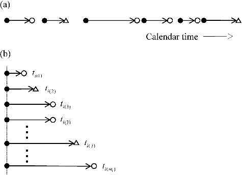
If the klystron system was brought back to its initial state by applying the rated high voltage to the klystron collector when the operation restarted, the klystron system was deemed to be repairable. As the condition of each restart point was assumed to be the same under this assumption, the MTBI evaluation of the ith klystron system could be deemed to be the lifetime test using Ni units of the ith klystron system [Citation5]. In this case, the MTBI expressed the MTBF. (b) shows the pattern diagram of the lifetime test using Ni units of the ith klystron system. In the figure, the arrows, whose total number is Ni, are arranged in order of ascending operation time, and their start points are on a vertical straight line. Using (b), the MTBI for the ith klystron system was calculated as below.
Let diℓ denote the number of klystron systems that failed in the ℓth interval ti(ℓ − 1) < t ⩽ ti(ℓ). Also, let riℓ denote the number of klystron systems that survived the ℓth interval and were right-censored at ti(ℓ). As the klystron systems that survived at the beginning of the jth interval are called the ‘risk set’ for the jth interval, the size nij of this risk set at the beginning of the jth interval is represented by the equation:
(9)
(9)
where it is understood that di0 = 0 and ri0 = 0. The maximum likelihood estimator
of the conditional probability of failing in the jth interval is defined as
(10)
(10)
A maximum likelihood estimator
of the survival function at t = ti(j) is
(11)
(11)
Using
defined in EquationEquation (11)
(11)
(11) , the MTBI λki for the ith klystron system is given by
(12)
(12)
where m'i is the maximum value for the serial number of the interval for the operation time ending in accidental interruption and is equal to or less than mi. Also, it is understood that ti0 = 0 and
.
For example, the value λki for the typical klystron system of i = 43 was obtained by substituting the operational data into EquationEquations (9)(9)
(9) –(Equation12
(12)
(12) ). Reliability parameters such as ti(j), nij, dij, rij, and
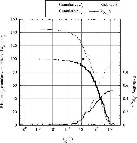
for each interval are tabulated in . The value nij of the first interval is evaluated as 145, accidentally coinciding with mi, because there are 92 accidental interruptions and 53 censored events, and each interval contains either one accidental interruption or one censored event. The survival function
decreases as the cumulative number of accidental interruptions increases. On the other hand, the survival function of the jth interval is equal to the value of the previous interval in the event that the jth interval has zero accidental interruption, such as j = 5. shows the value of nij as a function of the operation time. The value of
and cumulative numbers of dij and rij (
,
) are also shown in the same figure. Finally, the value of λki for i = 43 was evaluated as 73.9 ± 8.1 hours.
Table 1. Reliability parameters for the typical klystron system of i = 43
Figure 7. Values of the risk set nij, cumulative numbers of dij and rij, and the survival function as a function of the operation time for the 43rd klystron system.
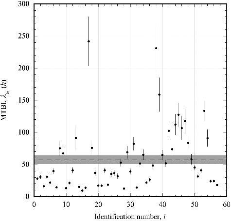
shows the MTBI λki as a function of the identification number of the klystron system. The dashed line and the gray rectangle in this figure represent the simple mean value and a standard error for λki. The mean value and its standard error is 57.3 ± 6.5 hours.
Figure 8. Value of the MTBI λki as a function of the identification number of the klystron system. The dashed line and the gray rectangle represent the simple mean value and its standard error for the MTBI λki.
Taking into account the above discussions, the MTBI found by the traditional estimation and the KM estimation is summarized in .
Table 2. Summary for MTBI for the klystron systems obtained by the traditional estimation and the KM estimation
Note that there was a underestimation of the MTBI for the klystron system for which the stop event with the longest operation time was the censored event, i.e. m'i < mi. Factors influencing the underestimation are presented in Appendix 2.
5. Discussion
In this section, the comparison is made by using the four types of MTBI mentioned in the previous section, and the cause for the difference between the KM estimation and the traditional estimation is investigated.
5.1. Ratio of censored events to accidental interruptions
In order to compare the four types of MTBI for the klystron systems, three types of ratios of the MTBI found by the KM estimation, to the MTBI found by the traditional estimation (,
,
), were derived for each klystron system. Hereafter, the ratio of the MTBI found by the KM estimation, to the MTBI found by the traditional estimation is referred to as the ‘MTBI ratio.’ shows the MTBI ratio as a function of the identification number of the klystron system. The dashed line and the gray rectangle in each small figure of represent the simple mean value and its standard error for the MTBI ratios. The mean values and their standard errors are 1.67 ± 0.07, 1.58 ± 0.06, and 1.14 ± 0.01 in order of figures, respectively. Differences between these mean values and one were statistically significant because P-values were lower than 0.0001. summarizes the MTBI ratios derived from the data points in .
Figure 9. Value of the MTBI ratio as a function of the identification number of the klystron system. The dashed line and the gray rectangle in each small figure represent the simple mean value and its standard error for the MTBI ratio (,
,
).
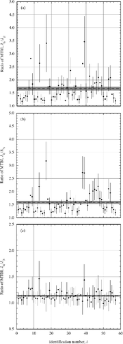
Table 3. Summary for the MTBI ratios of the klystron system
The relation between the MTBI found by the traditional estimation and the MTBI ratio for the klystron systems is shown in in order of the traditional method. Here, the open circles, solid circles, and cross marks in each small figure represent the data points located in Regions I, II, and III in , respectively. To reduce visual complication, no error bars in each small figure are indicated.
Figure 10. Relationship between the MTBI found by the traditional estimation and the MTBI ratio for the klystron systems in order of the traditional estimation. Two gray dashed lines in each small figure represent the simple mean value for the MTBI and the MTBI ratio of the klystron system.

According to the figures of the data points in , the characteristics of the MTBI ratios can be summarized as follows.
| (1) | Methods 1 and 2: | ||||
| (2) | a. For the klystron systems whose | ||||
| (3) | b. For the klystron systems in Regions II or III, the MTBI ratio was greater than about 1.2. Notably, for Region III, most MTBI ratios were greater than the simple mean value. | ||||
| (4) | Method 3: | ||||
| (5) | a. The MTBI ratio seemed to be independent of Regions I, II, and III. | ||||
Therefore, the MTBI ratios seemed to depend on the figures of the data points in for methods 1 and 2. On the other hand, the MTBI ratio seemed to be independent of these for method 3. In the next section, the relationship between the survival function of the klystron system and the MTBI ratio for method 3 is discussed.
5.2. Survival function of the klystron system
In general, it is considered that a product's lifetime is decided by the failure of its weakest part. In this case, a failure model of the product can be assumed to involve the Weibull distribution with two parameters [Citation5]. Its survival function R(t), i.e. the Weibull reliability function is given by
(13)
(13)
Here, t is time to failure, and the positive real numbers α and β are a scale parameter and a shape parameter, respectively. For 0 < β < 1, the Weibull reliability function is called an initial failure type because the failure rate decreases with time. With β > 1, the Weibull reliability function is called a wear-out type because the failure rate increases with time. When β = 1, the Weibull reliability function is called a random failure type or an exponential distribution because the failure rate is constant with time. Hereafter, the Weibull reliability function with β = 1 is referred to as the ‘exponential distribution.’’ In the event that the Weibull reliability function of the klystron system had the exponential distribution, the accidental interruption rate was constant with the operational time, and was judged to be the inverse of the MTBI.
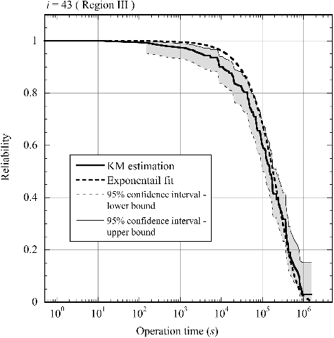
presents the survival function with 95% confidence intervals for the typical klystron system of i = 43. The survival function data of the 43rd klystron system are shown in , and the 95% confidence interval is estimated using the Greenwood formula [Citation5]. The region between the upper and lower bounds for the 95% confidence interval is colored gray. In , the exponential distribution approximated from the survival function data is also presented. The relationship between the set of the survival function data and the exponential distribution was evaluated with the correlation coefficient r2. The correlation coefficient r2 for the 43rd klystron system was 0.994.
Figure 11. Survival function with 95% confidence intervals for the 43rd klystron system. The region between the upper and lower bounds for the 95% confidence interval is colored gray. The thick gray dashed line represents the exponential distribution approximated from the survival function data.
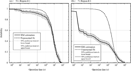
The distribution of the correlation coefficients is shown in . shows the relationship between the survival function data and the exponential distribution in the case of the klystron system with the best and worst correlations. The klystron system with the best correlation was the 51st one, and the value of r2 was 0.998. The survival function data of the 51st klystron system could be properly approximated by the exponential distribution although there were some differences between the data and the exponential distribution. On the other hand, the klystron system with the worst correlation was the seventh one, and the value of r2 was 0.933. By comparing them, it was obvious that the survival function data could not be approximated by the exponential distribution. The cause of this difference was that many accidental interruptions occurred at an early stage of the operation time.
Figure 12. Distribution of the correlation coefficients between the survival function data and the exponential distribution.
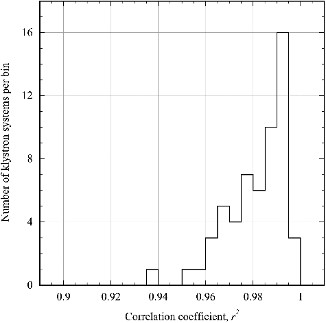
Figure 13. Relationship between the survival function data and the exponential distribution in the case of the klystron system with the (a) best and (b) worst correlations. The region between the upper and lower bounds for the 95% confidence interval is colored gray. The thick gray dashed line represents the exponential distribution approximated from the survival function data.
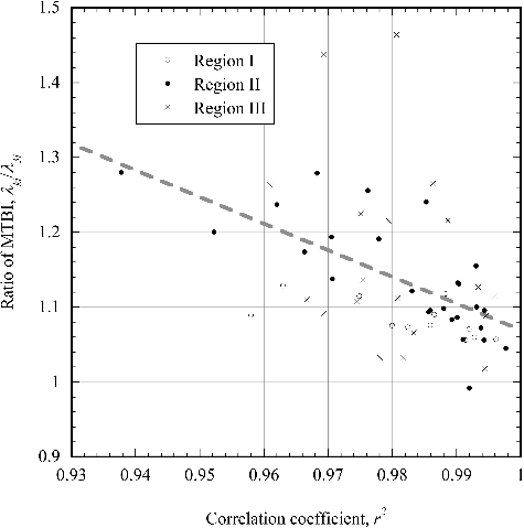
shows the relationship between the correlation coefficient r2 and the MTBI ratios . Here, the open circles, solid circles, and cross marks represent the data points located in Regions I, II, and III in , respectively. The gray dashed line represents the least-squares linear fit line approximated from all data points. From the figure, the MTBI ratio
tends to fall to one as the correlation coefficient r2 approaches one. Because the MTBI ratio
of several klystron systems was not equal to one, EquationEquation (6)
(6)
(6) could not be applied to calculate the MTBI for them, and the accidental interruption rate depended on the operational time and was not judged to be the inverse of the MTBI.
6. Conclusions
In order to overcome the beam-trip problem that occurred in the ADS, acceptable beam-trip frequencies of the ADS accelerator were evaluated and the beam-trip frequencies began to be estimated based on operational data on existing accelerators. However, there are at least three methods to calculate the MTBI for the klystron systems. In this study, the MTBI for the klystron systems of the KEK injector linac was evaluated, including censored events in addition to accidental interruptions, and using the KM estimation, which is a representative non-parametric reliability method. Also, the MTBI found by the reliability engineering method was compared with the traditional results. As a result, the following facts were confirmed.
In cases where censored events were defined as the manual termination of normal operation of the klystron system by operators due to regular maintenance and so on, the number of censored events was 22% that of accidental interruptions.
The mean value of the MTBI found by the KM estimation was 57.3 ± 6.5 hours. On the other hand, the mean values of the MTBI found by the three traditional methods were 30.9 ± 2.4, 32.0 ± 2.3, and 50.4 ± 5.9 hours. The mean values for the ratios of the MTBI found by the KM estimation, to the MTBI found by the traditional estimation were 1.67 ± 0.07, 1.58 ± 0.06 and 1.14 ± 0.01, respectively.
Survival functions of several klystron systems may not have had the exponential distribution; therefore, the accidental interruption rate depended on the operational time, and was not judged to be the inverse of the MTBI.
Although these results are obviously different from traditional results, it appears that the present estimation based on the reliability engineering method is suitable for the MTBI for accelerator components as typified by the klystron system, and appropriately evaluates the beam-trip frequency for the proton accelerator of JAEA's reference ADS.
Disclosure statement
No potential conflict of interest was reported by the authors.
References
- Tsujimoto K, Sasa T, Nishihara K, et al. Neutronics design for lead-bismuth cooled accelerator-driven system for transmutation of minor actinide. J Nucl Sci Technol. 2004 Jan;41:21–36.
- Tsujimoto K, Oigawa H, Ouchi N, et al. Research and development program on accelerator driven subcritical system in JAEA. J Nucl Sci Technol. 2007 Mar;44:483–490.
- Takei H, Nishihara K, Tsujimoto K, et al. Estimation of acceptable beam-trip frequencies of accelerators for accelerator-driven systems and comparison with existing performance data. J Nucl Sci Technol. 2012 Apr;49:384–397.
- Pierini P, Burgazzi L. ADS accelerator reliability activities in Europe. Proceedings of the 4th International Workshop on Utilisation and Reliability of High Power Proton Accelerators; 2004 May 16–19; Daejeon, Republic of Korea, 137–147, Organization for Economic Co-operation and Development (2005).
- Meeker QW, Escobar AL. Statistical methods for reliability data. New York: John Wiley & Sons; 1998. Chapter 3, Nonparametric estimation; p. 46–74.
- Castet JF, Saleh HJ. Satellite and satellite subsystems reliability: statistical data analysis and modeling. Reliab Eng Syst Saf. 2009 Nov;94:1718–1728.
- Abe I, Akasaka N, Akemoto M, et al. The KEKB injector linac. Nucl Instrum Methods A. 2003 Feb;499:167–190.
- Enomoto A. Upgrade to the 8-GeV electron linac for KEKB. Proceedings of the XVIII International Linear Accelerator Conference; 1996 Aug 26–30; Geneva, Switzerland, 633–637, Hill C, Vretenar M, editors (1997).
- JMP [CD-ROM]. Version 13.1.0 for Windows. Cary (NC): SAS Institute Inc.; 2017. 1 CD-ROM: color, 4 3/4 in. Accompanied by: 1 user's guide. English, Japanese.
Appendices
Appendix 1.
In the main text, the MTBI was first obtained for each klystron system and then these values were averaged by considering MTBI's differences in the klystron systems. On the other hand, the MTBI can be also evaluated when looking at an RF system comprising an assembly of the klystron systems as subsystems. In this appendix, the MTBI for the RF system was evaluated without discrimination of the klystron system. In other words, it was assumed that both 13,150 accidental interruptions and 2909 censored events were occurred on one klystron system. In this case, definitional equations of the MTBI, i.e. EquationEquations (4)(4)
(4) –(Equation6
(6)
(6) ), could be expanded, and the calculation results were given as follows:
(A1)
(A1)
(A2)
(A2)
(A3)
(A3)
On the other hand, the MTBI found by the KM estimation was evaluated as follows:
(A4)
(A4)
where trf(j) is the different operation time of the RF system for jth interval, m'rf is the maximum value for the serial number of the interval for the operation time ending in accidental interruption of 10,689, and
is the maximum likelihood estimator of the survival function at t = trf(j). shows the value of
as a function of the operation time. The values of the risk set nrfj and cumulative numbers of drfj and rrfj are also shown in the same figure, where nrfj, drfj, and rrfj are expansions of nij, dij, and rij, respectively. Therefore, the MTBI for the RF system under above-mentioned assumption is summarized in .
Figure A1. Values of the risk set nrfj, cumulative numbers of drfj and rrfj, and the survival function as a function of the operation time for the RF system.
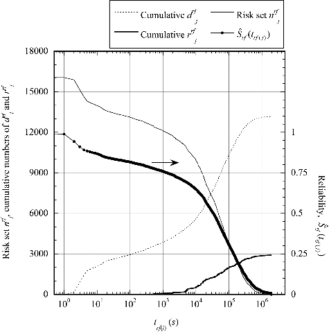
Table A1. MTBI for the RF system obtained by the traditional estimation and the KM estimation
Appendix 2.
The mean value of the MTBI for the klystron systems was 57.3 ± 6.5 hours when the average of all the klystron systems was taken. However, as there was an underestimation of the MTBI for the klystron system for which the stop event with the longest operation time was the censored event, it was possible that the mean value of the MTBI was different from 57.3 hours. Hereafter, the ‘biased klystron system’ refers to the klystron system for which the stop event with the longest operation time was the censored event. Also, the ‘non-biased klystron system’ refers to the klystron system for which the stop event with the longest operation time was an accidental interruption. In this appendix, the difference in the mean value of the MTBI depending on the type of klystron system, that is, a biased or non-biased klystron system, was investigated.
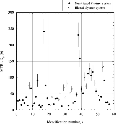
First, a study to determine which of the two types of klystron system showed that there were 41 klystron systems for the non-biased one, and 16 for the biased one. shows the MTBI for each klystron system depending on the type of klystron system. From this figure, the MTBI was 55.6 ± 8.6 hours when averaged over only the non-biased klystron systems. On the other hand, the MTBI was 61.7 ± 7.6 hours when averaged over only the biased klystron systems. In the latter case, it was presumed that the actual MTBI would be longer than 61.7 hours.
Figure B1. Value of the MTBI λki as a function of the identification number of the klystron system, depending on the type of klystron system. The closed and open circles represent the non-biased klystron system and the biased one, respectively.
In using the mean value of the MTBI for the klystron systems, it is necessary to make judgments and choose from among these three types of mean values, according to the purpose for which the mean value of the MTBI is used.

