
ABSTRACT
It is important to clarify the mechanisms of the dislocation loop formation, dissolution of precipitates to understand the degradation behavior of the fuel cladding tubes in light water reactors (LWR) under neutron irradiation. In this study, 3.2 MeV Ni ion irradiation was carried out at 400°C on Zircaloy-2 and two types of model alloys with and without Fe (Zr-1.5Sn-0.3Fe and Zr-1.5Sn). To understand the effects of hydrogen, 60 and 300 ppm pre-injected Zircaloy-2 samples were also irradiated. The microstructure was observed with a conventional transmission electron microscopy. Additionally, the dissolution of precipitates and the enrichment of the alloying element due to irradiation were analyzed using a spherical aberration (Cs)-corrected high-resolution analytical electron microscope. After ion irradiation at 400°C, the dissolution of Fe-enriched precipitates and the c-component dislocation loops were observed in the region of peak ion damage. Observations by STEM-EDS showed that Fe atoms were enriched in the c-component dislocation loops. On the contrary, the c-component dislocation loops were detected in Fe-containing alloys (Zircaloy-2 and Zr-1.5Sn-0.3Fe alloy) but were not in the Zr-1.5Sn alloy. These results indicate that the dissolution of Fe-enriched precipitates and the enhanced formation of c-component dislocation loops are essential for the degradation of LWR fuel cladding under irradiation.
1. Introduction
The irradiation growth of Zircaloy-2 leads to a macroscopic elongation in the axial direction of the claddings owing to the strong texture of the claddings [Citation1]. During the operation, an acceleration of the growth rate in the reactor, called ‘breakaway growth,’ occurs after an incubation dose of about 6 dpa [Citation2]. Holt et al. showed that the breakaway growth is correlated with the nucleation of the c-component dislocation loops formed at high doses [Citation3]. And there is a correlation between the existence of the c-component dislocation loops and the irradiation growth. As the burn-up of a light water reactor (LWR) fuel is extended, hydrogen pick-up increases in the Zircaloy cladding. Hydrogen embrittlement of Zircaloy is one of the main factors that limit the lifetime of the fuel rod. Therefore, to understand how the hydrogen pick-up during operation influences the growth acceleration, it is necessary to study the effect of hydrogen on the c-component loop formation. A c-component dislocation loop is a radiation-induced defect cluster and is formed via irradiation by neutrons [Citation4,Citation5], electrons [Citation6,Citation7], or charged particles [Citation8–Citation13]. Further, it has been shown that the second-phase particles (SPPs) formed in Zircaloy-2 [Citation14], the size distribution of the SPPs, and the chemical composition of the cladding affect the corrosion rate in the cladding inside boiling water reactors (BWRs) [Citation15–Citation20]. However, these SPPs are unstable during neutron irradiation and undergo an amorphous transformation, which results in decomposition and redistribution of precipitates in defect sinks [Citation18–Citation20]. Ion irradiation has been used on nuclear materials in many studies because, unlike neutron irradiation, the dpa level, irradiation temperature, and other irradiation conditions can be precisely controlled [Citation8–Citation13].
In this study, a 3.2 MeV Ni ion irradiation was applied to Zircaloy-2 and to two model alloys with and without Fe (Zr-1.5Sn-0.3Fe and Zr-1.5Sn); the irradiation temperature was 400°C and the dose was approximately 50 dpa. To understand the effects of hydrogen, 60 and 300 ppm pre-injected Zircaloy-2 samples were also irradiated. Following ion irradiation, the specimens were prepared by a focused ion beam (FIB) to observe the cross section. The microstructure was observed by conventional electron microscopy (C-TEM). Further, the dissolution of the SPPs and the enrichment of the alloying element due to irradiation were analyzed by spherical aberration (Cs)-corrected scanning transmission electron microscopy (STEM) combined with the X-ray energy-dispersive spectroscopy (EDS).
2. Experimental procedures
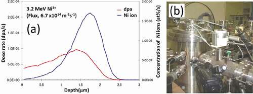
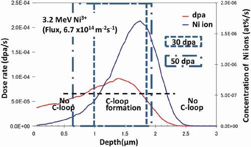
Zircaloy-2 and two model alloys, with and without Fe (Zr-1.5Sn-0.3Fe and Zr-1.5Sn), were used in this study. The specimens were annealed at 630°C for 2 h and subsequently air cooled, before ion irradiation. The results of the chemical analyses and the measurements of the hydrogen impurity level of these alloys are shown in . Ion irradiation with 3.2 MeV Ni3+ was applied at 400°C via the tandem accelerator at Kyushu University. () and () shows the stopping and ranges of ions in matter (SRIM) calculation [Citation21] of the damage distribution and the impurity (Ni ion) concentration of the pure Zr following irradiation and the specimen chamber used for ion irradiation, respectively. For the damage estimation, the threshold energy for displacement (Ed) was assumed to be 40 eV. () shows the estimated values in the case of 6.7 × 10¹⁴ ions/m2s. The maximum dose of the irradiation of the peak-damage region was 50 dpa. After the ion irradiation, thin foils were prepared for TEM observation by a focused ion beam (FIB) of Ar operating at 40 kV (FB2100, Hitachi Ltd., Japan). The cross-sectional view of the irradiated region was observed. The samples were finished by a low-energy Ar ion milling instrument operating at 1.5–3.0 kV (Dual Ion Mill 600, Gatan Ltd., USA), to minimize the damage from the FIB. Samples of about 0.2 mm in thickness were prepared and annealed at 500°C in a H2 purged atmosphere for 2 h, to investigate the effects of hydrogen on the microstructural evolution of Zircaloy-2. By these procedures, 60 or 300 ppm hydrogen pre-injected samples were prepared and subsequently ion irradiated.
Table 1. Chemical compositions of the materials used in the present study (wt%)
Figure 1. (a) SRIM calculation of the damage distribution in Zr irradiated by Ni ions at 3.2 MeV and (b) the specimen chamber used for the irradiation.
The microstructure was observed before and after the irradiation by conventional transmission electron microscopy (C-TEM) and high-resolution transmission electron microscopy (HRTEM). The dissolution of precipitates and the enrichment of the alloying element due to irradiation were analyzed using a spherical aberration (Cs)-corrected high-resolution analytical electron microscope (ARM200FC, JEOL, Japan) operating at a voltage of 200 kV in a radiation-controlled area at Kyushu University and using an analytical electron microscope (3000F, JEOL, Japan) operating at a voltage of 300 kV at the Wakasa Wan Energy Research Center.
3. Results
3.1. STEM-EDS analysis of unirradiated Zircaloy-2 and model alloys
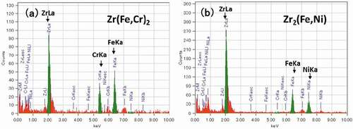
In Zircaloy-2, the following types of Zr precipitates are known to form in the matrix: intermetallic hcp-Zr2(Fe,Ni) and bct-Zr(Fe,Cr)2. The STEM-EDS map of unirradiated Zircaloy-2 in shows relatively large (about 30 nm) Zr2(Fe,Ni) precipitates and small Zr(Fe,Cr)2 precipitates in the vicinity of the Zr2(Fe,Ni) precipitates in the matrix. () and () shows EDS spectrum of Zr(Fe,Cr)2 precipitates and Zr2(Fe,Ni) precipitates, respectively. The number density of Zr(Fe,Cr)2 and Zr2(Fe,Ni) precipitates were 2.0 × 10¹⁹ and 3.2 × 10¹⁸ m−3, respectively. The presence of these two types of intermetallic precipitates is in agreement with the results reported by Chemelle et al. [Citation14].
Figure 2. STEM-EDS mapping of annealed Zircaloy-2.
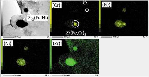
Figure 3. EDS spectrum of (a) Zr(Fe,Cr)2 precipitate and (b) Zr2(Fe,Ni) precipitate before irradiation.
3.2. The formation of c-component dislocation loop in Zircaloy-2 and the model alloys
shows C-TEM images of Zircaloy-2 irradiated with a dose of 30 dpa at 400°C. () and () shows a cross-sectional view of the irradiated region including the specimen surface at low-magnification and higher-magnification images of the peak-damage region, respectively. The images show that the c-component dislocation loops formed at a spacing of about 30–40 nm in the peak-damage region (at a depth of 1.0–1.8 μm from the surface of specimen). The c-component dislocation loops were clearly observed when the diffraction vector was parallel to the <c> axis (g = <0002>). The region where the c-component dislocation loops were detected was enlarged in the sample irradiated with a dose of 50 dpa (at a depth of 0.6–1.9 μm from the surface of specimen) compared with the sample that was irradiated with a dose of 30 dpa. () and () shows C-TEM images of the c-component dislocation loops and a HRTEM image of the same region with a dose of 50 dpa, respectively. There was no clear change in the appearance or spacing of the c-component dislocation loops due to the change in the dose. The value of 0.51 (nm) inserted in () corresponds to lattice constant in Zr along <c> direction. Moreover, large lattice expansions (shown by arrows in the figure) caused by radiation-induced Fe segregation and/or hydride formation on the basal plane were also observed.
Figure 4. C-TEM images of Zircaloy-2 irradiated with a dose of 30 dpa at 400°C: (a) cross-sectional view of the irradiated region including the specimen surface (lower magnification) and (b) higher magnification images of the peak-damage region.
Figure 5. (a) C-TEM images of c-component dislocation loops (b) and the corresponding HRTEM image of the region shown in (a).
() and () shows C-TEM images of Zr-1.5Sn and Zr-1.5Sn-0.3Fe alloys, respectively, following irradiation with a dose of 30 dpa at 400°C. C-component dislocation loops were identified in the Zr-1.5Sn-0.3Fe alloy but not in the Zr-1.5Sn alloy.
Figure 6. C-TEM images of the samples irradiated with a dose of 30 dpa at 400°C: (a) Zr-1.5Sn alloy and (b) Zr-1.5Sn-0.3Fe alloy.
3.3. Resolution of SPPS and Fe enrichment at the sinks
shows STEM-EDS maps of Zircaloy-2 irradiated with a dose of 30 dpa at 400°C. The region between the two dotted lines in () is where c-component dislocation loops were observed. () and () shows influence of the dose on elemental content ratios of Zr(Fe,Cr)2 and Zr2(Fe,Ni) precipitates, respectively. As shown in and , Fe atoms dissolved out of the Zr(Fe,Cr)2 precipitates by the irradiation up to 30 dpa. However, Zr2(Fe,Ni) precipitates in Zircaloy-2 under the same irradiation conditions were stable.
Figure 7. STEM-EDS analysis of Zircaloy-2 irradiated with a dose of 30 dpa at 400°C: (a) bright-field image, (b) chemical maps extracted from a spectral image, and (c) a line scan of a precipitate.
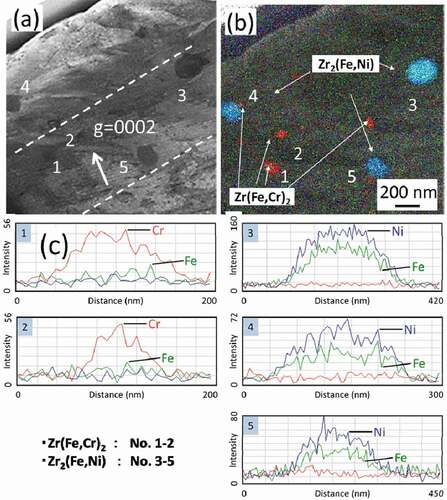
Figure 8. Influence of the dose on elemental content ratios of (a) Zr(Fe,Cr)2 and (b) Zr2(Fe,Ni) precipitates.
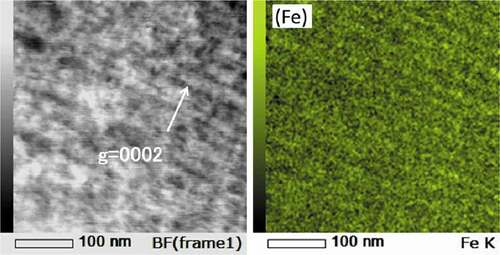
shows STEM-EDS maps of Zircaloy-2 irradiated with a dose of 50 dpa at 400°C. () and () shows the Cr and Fe maps of the irradiated region, including the specimen surface (low-magnification) and higher-magnification Ni and Fe maps of the peak-damage region, respectively. As shown in (), the number density of the Zr(Fe,Cr)2 precipitates in the irradiated region was comparable with that in the unirradiated region but the Fe atoms almost completely dissolved out of the Zr(Fe,Cr)2 precipitates and were enriched on the c-component dislocation loops. However, Fe enrichment on the loops is weak compared to Ni. Ni enrichment, presumably due to the implanted ions, was also detected. and show STEM-EDS maps of Zr-1.5Sn-0.3Fe alloy irradiated with a dose of 30 dpa at 400°C. Fe enrichment was also detected at the interface between matrix and hydride (visible in ) and also on c-component dislocation loops (visible in .
Figure 9. STEM-EDS mapping of Zircaloy-2 irradiated with a dose of 50 dpa at 400°C: (a) Cr and Fe map of the irradiated region including the specimen surface (low magnification) and (b) high magnification of Ni and Fe map of the peak-damage region.
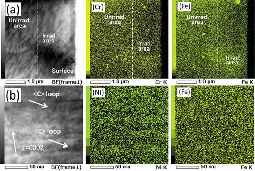
Figure 10. STEM-EDS mapping of Zr-1.5Sn-0.3Fe alloy irradiated with a dose of 30 dpa at 400°C (Fe, Sn, and Zr mapping).
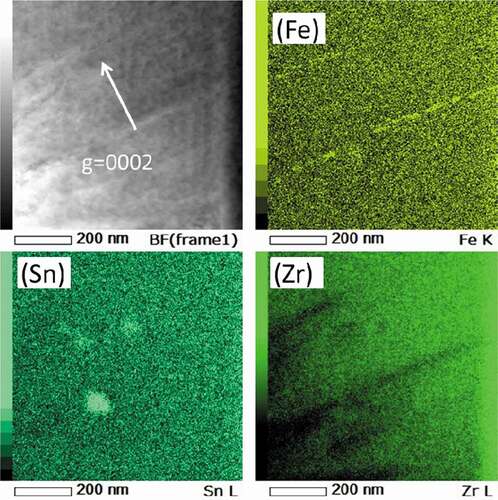
Figure 11. STEM-EDS mapping of Zr-1.5Sn-0.3Fe alloy irradiated with a dose of 30 dpa at 400°C (Fe mapping).
3.4. Hydride formation in Zircaloy-2
To investigate the effects of hydrogen on the microstructural evolution of Zircaloy-2, 60 and 300 ppm hydrogen samples were pre-injected prior to the irradiation. shows STEM-EDS maps of Zircaloy-2 irradiated with injected hydrogen. Plate-like hydrides nucleated at the boundary between the matrix and the Zr(Fe,Cr)2 precipitate. The growth direction of the hydrides was <112¯0> Zr. Based on the preferential growth direction of the precipitates, they were assumed to be δ-hydride, which is in agreement with the finding reported in a previous study [Citation22,Citation23]. shows a magnified STEM-BF image of the δ-hydride associated with the Zr(Fe,Cr)2 precipitate. Dislocation lines were observed around the δ-hydride, as reported in previous studies [Citation22,Citation23]. After the ion irradiation with 30 dpa at 400°C, the microstructure was observed by TEM. In samples irradiated with pre-injected hydrogen, no identifiable c-dislocation loops were formed with the dose at which they are commonly observed in non-injected samples.
Figure 12. STEM-EDS mapping of Zircaloy-2 irradiated with 300 ppm of injected hydrogen: bright-field and chemical maps extracted from a spectral image of a precipitate.
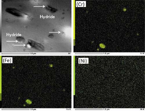
Figure 13. Magnified STEM-BF image of the δ-hydride associated with the Zr(Fe,Cr)2 precipitate.
In this study, to obtain a cross-sectional view, the samples were prepared using a FIB. However, the small damage caused by the FIB was not negligible, even after polishing Ar ion at the lowest energy. STEM-BF imaging was used in this study to avoid the imaging coming from the specimen preparation by FIB. () and () shows STEM-BF images of the sample before and after irradiation with a dose of 30 dpa at 400°C, respectively. The STEM-BF images clearly show that δ-hydrides (shown by arrows in the figure) formed on the basal planes with and without irradiation while () shows a decrease in the number density of the hydrides in the region where c-component loops were detected.
Figure 14. STEM-BF images of Zircaloy-2: (a) microstructure of an unirradiated region exposed to the same heat conditions at 400°C with a dose of 30 dpa and (b) microstructure of the peak-damage region of the sample irradiated with a dose of 30 dpa at 400°C.
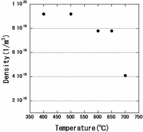
() and () shows the measured number density of hydrides in an unirradiated region and in a region irradiated with a dose of 30 dpa at 400°C, respectively. The number density of small hydrides (about 200 nm) was decreased by the irradiation. Samples were annealed at higher temperatures for 30 min to investigate the thermal stability of the hydrides and the c-component dislocation loops. The microstructures observed at each temperature were shown in . The density of the hydrides began to decrease upon annealing at 600°C and decreased further after annealing at 700°C, as shown in .
Figure 15. Size distributions of δ-hydride: (a) unirradiated region exposed to the same heat conditions with a dose of 30 dpa at 400°C and (b) the peak-damage region of the sample irradiated with a dose of 30 dpa at 400°C.
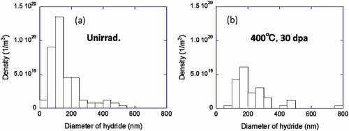
Figure 16. Influence of the annealing temperature on the microstructure in irradiated and unirradiated regions.
Figure 17. Number density of δ-hydrides at different annealing temperatures.
4. Discussion
4.1. Effects of Fe on c-component loop formation
Early reports of c-component loops produced by irradiation of zirconium and zirconium alloys [Citation24] were ambiguous because insufficient distinction was made between the induced defects and thin foil artifacts (e.g. surface contamination, surface hydrides). These samples show the so-called ‘corduroy’ contrast. More detailed analyses on neutron irradiated samples show these defects are vacancy, basal plane dislocation loops having Burgers vectors of b = 1/6 < 202¯3> [Citation20]. Moreover, Jonstsons et al. [Citation4] showed that c-component loops formed in samples of Zr, with a high impurity content at temperatures above 452°C with a neutron dose of 1.3 × 1025 n/m2 (E > 0.1 MeV), corresponds to about 3 dpa in Zr alloys [Citation25]. It has also been shown that the formation of loops depends on the impurity level and the alloying elements [Citation19,Citation20].
In this study, to avoid the artifacts due to thin foil TEM specimen preparation, the surface of the samples was finally polished by Ar ion milling operating at 1.5–3.0 kV. To confirm the c-component loop formation, C-TEM images were taken from different Bragg condition. shows images of c-component loops formed in Zr-1.5Sn-0.3Fe alloy irradiated with a dose of 30 dpa. (a) and (b) shows the case of the difference from Bragg condition (s) is close to zero (a) and s > 0 (b), respectively. Under these conditions, the radiation-induced c-component loops exhibit parallel lines of loops depending on s. shows images of lines of c-component loop observed near grain boundary. C-component loops were detected on each basal habit plane across the grain boundary. The c-component loop formation was detected in Zircaloy-2 in the region of 1.0–1.8 µm with a dose of 30 dpa and in 0.6–1.9 µm for 50 dpa. As shown in , for these dose levels, each irradiated region corresponds to a region where the dose level was higher than 23–25 dpa. In this study, c-component dislocation loops were not detected in the samples irradiated with a dose of 15 dpa at 400°C, which is well recognized as the threshold dose for dislocation loop formation.
Figure 18. C-TEM images of Zr-1.5Sn-0.3Fe alloy irradiated with a dose of 30 dpa at 400°C: (a) difference from Bragg condition (s) is close to zero and (b) s > 0.

Figure 19. C-TEM images of c-component dislocation loops formed near grain boundary: Zr-1.5Sn-0.3Fe alloy with a dose of 30 dpa at 400°C.
Figure 20. Influence of the dose (30 and 50 dpa) on the region where the c-component dislocation loops formed.
As described in Section 3.2, c-component loop formation was detected in Zircaloy-2 and Zr-1.5Sn-0.3Fe alloy, but not in Zr-1.5Sn alloy. Therefore, it is concluded that the Fe atoms are vital for the formation of c-component dislocation loops. Moreover, c-component dislocation loops were detected after irradiation with dose levels which resulted in a notable dissolution of the Zr(Fe,Cr)2 precipitate. Enrichment of Fe atoms was detected on the c-component dislocation loops and at the grain boundaries. It is known that the solubilities of Fe, Ni, and Cr are small (< 0.02 at%) and that most of these elements are precipitated as intermetallic compounds [Citation26] so there should be little effect on the amount in solution. However, the results show that the Fe atoms dissolved from Zr(Fe,Cr)2 precipitates strongly promoted the nucleation of c-component dislocation loops in the matrix. A similar enhancement of the formation of c-component dislocation loops by Fe addition in pure Zr has been reported previously [Citation27]. Moreover, the strong enrichment of Fe and Ni atoms at the defect sinks () indicates a higher binding energy between these atoms and point defects (probably interstitials). The segregation of Fe and Ni atoms to the basal planes was also observed in proton-irradiated Zircaloy-2 by Harte et al. [Citation28]. Furthermore, fast and anisotropic diffusion of interstitial Fe, Cr, and Ni atoms in the c-direction was shown by ab initio calculations [Citation29].
4.2. Application of Ni ion irradiation to Zr alloys
Previous work on sponge Zr [Citation20] after neuron irradiation showed that the c-component dislocation loops were clustered in bands parallel with the basal plane and precipitates from impurities (mainly Fe and Cr atoms) were also concentrated in the same band. Probably, c-component loops nucleated in zones where the concentration of impurity was high. The microstructure of Zircaloy-2 over the temperatures from 300°C to 600°C by 5.0 MeV Ni ion irradiation was also studied by Lee et al. They reported a well-defined alignment of defects with the projection of aligned defects oriented in the <101¯0> directions. A detailed examination by TEM of these defects revealed that they exhibit two kind types of images: one is associated with precipitation of second phase and the other with lattice displacement due to irradiation [Citation8]. In this study, 3.2 MeV Ni3+ ion was used to produce the damage, but this ion has a low solubility in Zr; the implantation of Ni atoms might be to introduce some strange features especially at higher dose levels. But in this study, no c-component loops were observed in the specimen without Fe element (see ). Impurity (Ni atoms) concentration of the samples was estimated to be ~0.51 (at%) at the peak-damage region of 30 dpa.
Yamada et al. [Citation11] studied the microstructure of pure Zr and Zircaloy-2 irradiated with Zr (self) ions by TEM. They found that the c-component dislocation loops formed in neutron irradiated Zircaloy-2 could be obtained by self-ion irradiation. They also found that the c-component dislocation loops formed in the damage levels of 15, 20, and 40 dpa at 400°C, which are comparable to the threshold dose (23–25 dpa) for dislocation loop formation obtained by the present Ni ion irradiation at 400°C. But, to avoid the impurity effects on c-component dislocation loop formation, Zr (self) ion irradiation on Zircaly-2 is ideal.
4.3. Coupling effect of hydride formation and irradiation
As described in Section 3.4, the Zircaloy-2 irradiated with a pre-injected hydrogel shows a higher dislocation density around the δ-hydrides. Furthermore, c-component dislocation loops were not detected, in contrast to samples irradiated without hydrogen under the same conditions. Shinohara et al. observed successive dislocation formation around δ-hydrides by in situ observation of Zircaloy-2 at 400°C [Citation12]. Therefore, the absence of c-component dislocation loops in Zircaloy-2 irradiated with a pre-injected hydrogen is most likely related to the deletion of Fe atoms from matrix due to the enrichment of the Fe atoms in the defect sinks (for example, dislocation and δ-hydrides) observed here.
In the Zircaloy-2 irradiated with pre-injected hydrogen, δ-hydride formed at the boundary between the Zr(Fe,Cr)2 precipitates and the matrix. This means that preferential nucleation of the hydride on the boundary compensates for the large volume misfit cause by the formation of hydride. The HRTEM image ()) shows this large expansion on the c-component dislocation loops in the sample irradiated at 400°C. The expansions caused by a radiation-induced Fe segregation may also act as the nucleation sites for hydrides with higher doses. Moreover, as shown in , small hydrides of about 200 nm formed in the sample were disappeared by the irradiation at 400°C but were stable after annealing up to 500°C and disappeared after annealing at 600°C. Given this information, fundamental studies of the coupling effect of hydrides and defect formation at higher doses are essential to confirm the degradation mechanisms of LWR fuel cladding under irradiation.
5. Conclusion
By combining C-TEM, HRTEM, STEM imaging, and EDS mapping, the micro-structural and micro-chemical evolution of 3.2 MeV Ni3+ ion-irradiated Zircaloy-2 and two model alloys, with and without Fe (Zr-1.5Sn-0.3Fe and Zr-1.5Sn), was investigated. Dissolution of SPPs and formation of c-component dislocation loops were observed in Fe-containing alloys up to a dose of 23–25 dpa. The c-component dislocation loops were detected in the Zr-1.5Sn-0.3Fe alloy but not in the Zr-1.5Sn alloy under the same irradiation conditions. A chemical analysis by Cs-corrected STEM showed Fe segregation to the basal plane. Therefore, it can be concluded that the nucleation of the c-component dislocation loops is controlled by the Fe atoms dissolved from the SPPs. Furthermore, the large expansions caused by the radiation-induced Fe segregation on the basal plane also act as the nucleation sites for hydrides at higher dose levels. A Ni atom has a low solubility in Zr; the implantation of Ni atoms might be to introduce some strange features especially at higher dose levels. To avoid the Ni impurity effects on c-component dislocation loop formation, Zr (self) ion irradiation on Zircaly-2 and model alloys is ideal.
Acknowledgments
This research was sponsored by the Ministry of Education, Culture, Sports, Science and Technology (MEXT) of JAPAN, under the Strategic Promotion Program for Basic Nuclear Research entitled ‘Research and Development of RBWR for High Transuranium Elements Burner.’ This work was also partially supported by the Collaborative Research Program of Research Institute for Applied Mechanics, Kyushu University.
Disclosure statement
No potential conflict of interest was reported by the authors.
References
- Lemaignan C, Motta AT. Zirconium alloys in nuclear applications. In: Materials Science and Technology. Weinheim: VCH; 1994. p. 455.
- Griffiths M, Gilbert RW, Fidleris V. Accelerated irradiation growth of Zirconium alloys. In: Zirconium in the Nuclear Industry: Eighth International Symposium, STP 1023; 1989. p. 658–677.
- Holt RA, Gilbert RW. Component dislocation in annealed Zircaloy irradiated at about 570K. J Nucl Mater. 1986;137(3):185–189.
- Jonstsons A, Kelly PM, Blake RG, et al. Neutron irradiation-induced defect structure in zirconium. ASTM STP. 1979;683:46–61.
- Griffiths M. A review of microstructure evolution in zirconium alloys during irradiation. J Nucl Mater. 1988;159:190–218.
- Griffiths M, Loretto MH, Smallman RE. Electron damage in zirconium. J Nucl Mater. 1983;115:313–332.
- Griffiths M, Styles RC, Woo CH, et al. Study of point defect mobilities in zirconium during electron irradiation in a high-voltage electron microscope. J Nucl Mater. 1944;208:324–334.
- Lee D, Koch EF. Irradiation damage in Zircaloy-2 produced by high dose ion bombardment. J Nucl Mater. 1974;50:162–174.
- Tournadre L, Onimus F, Bechade J-L, et al. Experimental study of the nucleation and growth of c-component loops under charge particle irradiation of recrystallized Zircaloy-4. J Nucl Mater. 2012;425:76–82.
- Tournadre L, Onimus F, Bechade J-L, et al. Toward a better understanding of the hydrogen impact on the radiation induced growth of zirconium alloys. J Nucl Mater. 2013;441:222–231.
- Yamada S, Kameyama T. Observation of c-component dislocation structures formed in pure Zr and Zr-base alloy by self-ion accelerator irradiation. J Nucl Mater. 2012;422:167–172.
- Shinohara Y, Abe H, Iwai T, et al. In situ TEM observation of growth process of zirconium hydride in Zircaloy-4 during hydrogen ion implantation. J Nucl Sci Technol. 2009;46:564–571.
- Idress Y, Yao Z, Kirk MA, et al. In situ study of defect accumulation in zirconium under heavy ion irradiation. J Nucl Mater. 2013;433:95–107.
- Chemelle P, Knorr DB, Van Der Sand JB, et al. Morphology and composition of second phase precipitates in Zircaloy-2. J Nucl Mater. 1983;113:58–64.
- Taegtstrom P, LimBaeck M, Dahlbaeck M, et al. Effects of hydrogen pickup and second phase particle dissolution on the in-reactor corrosion performance of BWR cladding. ASTM STP. 2002;1423:96–118.
- Valizadeh S, Ledergerber G, Abolhassani S, et al. Effects of secondary phase particle dissolution on the in-reactor performance of BWR cladding. STM STP. 2011;1529:729–753.
- Sundell G, Thuvander M, Tejland P, et al. Redistribution of alloying elements in Zircaloy-2 after in-reactor exposure. J Nucl Mater. 2014;454:178–185.
- Griffiths M, Gilbert RW, Carpenter GJC. Phase instability decomposition and redistribution on intermetatllic precipitates Zircaloy-2 and -4 during neutron irradiation. J Nucl Mater. 1987;150:53–66.
- Griffiths M, Gilbert RW, Fidleris V, et al. Neutron damage in zirconium alloys irradiated at 644 to 710K. J Nucl Mater. 1987;150:159–168.
- Griffiths M, Gilbert RW. The formation of c-component defects in zirconium alloys during neutron irradiation. J Nucl Mater. 1987;150:169–181.
- Ziegler ZF. SRIM – the stopping and ranges of ions in matter. http://www.srim.org
- Bradbrook JS, Lorimer GW, Ridley N. The precipitation of zirconium hydride in zirconium and Zircaloy-2. J Nucl Mater. 1972;42:142–160.
- Carpenter GJC, Watters JF, Gilbert RW. Dislocations generated by zirconium hydride precipitates in zirconium and some of its alloys. J Nucl Mater. 1973;48:267–276.
- Bell WL. Corduroy contrast observation in neutron-irradiated zirconium and Zircaloy. J Nucl Mater. 1975;55:14–22.
- Waterside corrosion of Zirconium alloy in nuclear power plants. 1999. https://inis.iaea.org/search/search.aspx?orig_q=RN:30056080
- Oestberg G. Determination of the composition of the second phase in Zircaloy. J Nucl Mater. 1962;7:103–106.
- De Carlan Y, Regnard C, Griffiths M, et al. Influence of iron in the nucleation of <c> component dislocation loops in irradiated Zircaloy-4. ASTM STP. 1996;1295:638–653.
- Harte A, Seymour T, Francis EM, et al. Advances in synchrotron x-ray diffraction and transmission electron microscopy technique for the investigation of microstructure evolution in proton- and neutron-irradiated zirconium alloys. J Mater Res. 2015;30(9):1349–1365.
- Christensen M, Wolf W, Freeman CM, et al. Effects of alloying element on the properties of Zr and Zr-H system. J Nucl Mater. 2014;445:241–250.