 ?Mathematical formulae have been encoded as MathML and are displayed in this HTML version using MathJax in order to improve their display. Uncheck the box to turn MathJax off. This feature requires Javascript. Click on a formula to zoom.
ABSTRACT
Electrorefining of irradiated metallic fuels (burn-up ~ 7 at%) in a LiCl-KCl melt at 773 K was successfully demonstrated: Actinides in the fuels were anodically dissolved in the melt. Both a selective U metal deposition on a solid cathode and a grouped recovery of actinides, U, Pu, Np, Am, and Cm, in a liquid Cd cathode were confirmed. The behavior of fission products, such as lanthanides, alkali metals, alkaline earth metals, and noble metals, were also investigated. It was found that the behaviors of actinides and fission products in the electrorefining of the fuels with ~ 7 at% burn-up were similar to those in electrorefining of fuels with ~ 2.5 at% burn-up.
KEYWORDS:
1. Introduction
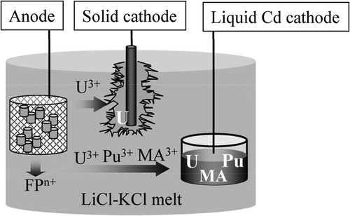
Pyrochemical processes have been developed worldwide to reprocess spent nuclear metallic fuels [Citation1,Citation2]. They utilize molten salt and liquid metal as the reaction media and therefore, possess the following intrinsic features; a high proliferation resistance, a high stability against radiation, a compact and flexible batch process concept, and so on. Recently, the pyrochemical processes experience increasing interest in the partitioning and transmutation scenario pursuing a significant reduction of the environmental burden of the long-lived nuclides contained in radioactive wastes [Citation2,Citation3]. Electrorefining is the main step of the pyrochemical processes, in which actinides (U, Pu, Np, Am, and Cm) in spent metallic fuels are recovered separating them from fission products according to their electrochemical properties in molten chlorides. shows the concept of the electrorefining. The chopped fuel pins are loaded in a metallic basket to be used as the anode in the LiCl-KCl melt. Then, actinides (An) in the fuel pins anodically dissolve to form their cations in the melt,
Two kinds of cathodes are employed to recover the actinides; an inert solid cathode and a reactive liquid Cd cathode. According to the redox potentials of actinides on the solid and liquid Cd electrodes, the bulk U metal is deposited on the solid cathode selectively (reaction 2) and all remaining actinides are simultaneously recovered in the liquid Cd cathode (reaction 3),
The irradiated metallic fuel has characteristic structures, such as the fuel components re-distribution according to temperature gradient induced inside the fuel (higher at the center and lower at the periphery), the formation of radial cracks and pores due to the irradiation swelling and so on [Citation4–Citation9]. Therefore, to design the electrorefining process and to evaluate its practicality, it is inevitable to carry out at the end electrorefining tests using irradiated fuels also to understand the behaviors of actinides and fission products. The spent metallic fuels from the Experimental Breeder Reactor-II (EBR-II) have been treated at Idaho National Laboratory since 1990s [Citation10–Citation12]; however, knowledge on the detailed behaviors of minor actinides and fission products were not fully reported. Thus, in our previous reports [Citation13,Citation14], the anodic behavior of the irradiated metallic fuels of a low burn-up (~ 2.5 at%) was investigated: Almost all of actinides in the irradiated fuels dissolved anodically in a LiCl-KCl melt (reaction 1). A selective U metal deposition on the solid cathode (reaction 2) and a grouped recovery of actinides in liquid Cd (reaction 3) were confirmed. Furthermore, concerning fission products, it was found that lanthanides, alkali metals, and alkaline earth metals dissolved and accumulated in the melt while noble metals remained in the fuel residues.
The characteristics of the irradiated fuel, the structure and the amounts of actinides and fission products, depend on the burn-up [Citation4–Citation9]. Therefore, in the present study, electrorefining tests using the irradiated metallic fuels of a higher burn-up, ~ 7 at%, was carried out to accumulate knowledge and eventually understand the influence of burn-up on the behaviors of actinides and fission products during electrorefining.
2. Experimental
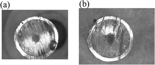
The metallic fuel used in the present study was a U-Pu-Zr alloy containing minor actinides (MA) and rare earths (RE), irradiated in the PHENIX reactor in France up to ~ 7 at% of burn-up [Citation6–Citation9]. The approximate composition of the metallic fuel rod before the irradiation was as follows (number in wt%); 67-U, 20-Pu, 9-Zr, 2-MA (1.2-Np, 0.7-Am and 0.2-Cm) and 2-RE (1.3-Nd, 0.1-Y, 0.2-Ce and 0.2-Gd). Part of the irradiated fuel rod was cut into two segments. The cut surface of the fuel segments showed the metallic luster as seen in . The length and weight including the cladding of the fuel segments were 5.36 mm, 1.828 g (segment No. 1) and 6.5 mm, 2.274 g (segment No. 2). The outer diameter of the fuel segments was 6.55 mm. The initial amount of each element in the fuel segments was calculated by using ORIGEN code [Citation15] and the composition is listed in . According to reports [Citation6–Citation9], the structure and composition of the fuel with burn-up of ~ 7 at% were different from the metallic fuel with burn-up of ~ 2.5 at% used in our previous study [Citation13,Citation14]: The radial cracks formed at burn-up of ~ 2.5 at% close at burn-up of ~ 7 at% owing to an increase of the fission gas volume. Furthermore, the fuel matrix constituents, U, Pu, and Zr, are redistributed, which generates concentric areas with different alloy compositions according to the temperature gradient induced in the fuel during irradiation. γ + ζ and δ + ζ phases exist at the center and at the periphery of the fuel used in this study, respectively. On the other hand, in the fuel used in our previous study (burn-up of ~ 2.5 at%), three concentric areas are formed; γ phase at the center, γ + ζ phase at the intermediate and δ + ζ phase at the outer area.
Table 1. Initial amounts in fuel segments No. 1 and 2 calculated by ORIGEN code [Citation15]. The migration of alkali and alkaline earth elements to the plenum during the irradiation is not taken into account
Two electrorefining runs (RUN1 and RUN2) were performed in a hot cell installed in JRC-KA. The atmosphere in the hot cell was Ar gas purified to keep the concentrations of oxygen and moisture below 20 ppm. The electrolyte was eutectic LiCl-KCl, ~ 96 g, melted at 773 K in an alumina crucible. Since the melt was the one used in our previous electrorefining tests [Citation13,Citation14], the melt initially contained actinides chlorides and fission products chlorides (lanthanide, alkali, and alkaline earth chlorides) originated from the irradiated metallic fuels (burn-up of ~ 2.5 at%). Fuel segments No. 1 and 2 were loaded in a steel mesh basket, which was used as the anode for both runs. A liquid Cd cathode was used at RUN1. The liquid Cd cathode was composed of Cd metal, 3.739 g, loaded in a small alumina crucible (9 mm inner diameter, 18 mm height) with a Ta wire lead. The Ta wire was covered by an alumina insulator to avoid a contact to the melt directly. A low carbon steel rod rotating at 50 rpm was used as the solid cathode at RUN2. The solid cathode was removed from the melt at electrolysis time 7.05 × 10⁴ s to scrape the deposit from the rod. Then, the same rod was used until the end of RUN2. Usually, a Ag/AgCl reference electrode is used for electrochemical measurements of actinides and lanthanides in a LiCl-KCl melt. However, due to a high radiation from the irradiated materials, it was found that the potential of the Ag/AgCl reference electrode was not stable for a long period [Citation16]. Therefore, a U/UCl3 reference electrode was tested in the present study. In a mullite tube, U metal piece fixed by a Ta lead wire was immersed in a LiCl-KCl-2.9wt%UCl3 melt. Potential values in this study are given with reference to the U/UCl3 reference electrode.
All samples, the fuel residues separated from the cladding, the Cd ingot recovered from the liquid Cd cathode, the deposits scraped from the solid cathode rod, the bulk salts and the precipitates at the bottom of the crucible, were dissolved in acids to be analyzed quantitatively by Inductively Coupled Plasma Mass Spectroscopy (ICP-MS). The fuel residues were dissolved completely in the mixture of HNO3 and HF at 453 K in a tight container (bomb dissolution). The rest of the samples, the salts, Cd ingot, solid cathode deposits and precipitates, were dissolved in HNO3. In case that undissolved particles were found after the dissolution in HNO3, aqua regia was added to the solution and/or the bomb dissolution was performed to obtain the clear solution. The solid cathode deposits, Cd ingot and fuel residues were washed by distilled water to remove the adhered salt before the dissolution in acids. Since an yttria mold had been used to fabricate the fuel rod used in this study [Citation8], Y detected by ICP-MS originates from not only the fuel also the mold. Thus, the quantitative evaluation on Y was not performed in this study.
3. Results and discussion
3.1. Electrorefining RUN1 and RUN2
Electrochemical measurements, cyclic voltammetry, and polarization measurements were performed to determine the electrolysis condition of the electrorefining RUNs. ) and (b) show cyclic voltammograms of W wire and liquid Cd electrodes, respectively. A cathodic and anodic current peak couple corresponding to U metal deposition (reaction 2) and dissolution (reaction 4), respectively, is observed at about 0 V vs. U/UCl3 ref. in ) [Citation17],
Figure 3. Cyclic voltammograms of (a) W wire and (b) liquid Cd electrodes in the melt. Scan rate was (a) 100 mV s−1 and (b) 20 mV s−1.
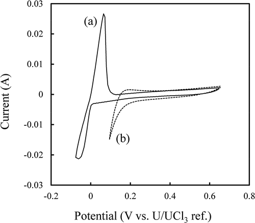
It was confirmed that actinide deposition in liquid Cd (reaction 3) proceeded at a lower potential than 0.2 V as can be seen in the cyclic voltammogram in ) [Citation18,Citation19]. A polarization curve of the metallic basket containing fuel segments No. 1 and 2, and that of a Zr metal plate are shown in . The polarization curves suggested that actinides in the fuel segments dissolved at a potential higher than 0 V (reaction 1), while Zr metal dissolution (reaction 5) occurred at a potential higher than 0.35 V [Citation20,Citation21].
Figure 4. Polarization curves of (a) anode basket containing fuel segments No. 1 and 2, and (b) Zr metal in the melt.
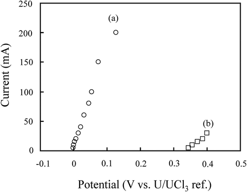
The above results indicated that the Zr dissolution from the fuel segments was limited as long as the potential of the anode basket would be kept below 0.35 V during electrorefining RUN1 and RUN2.
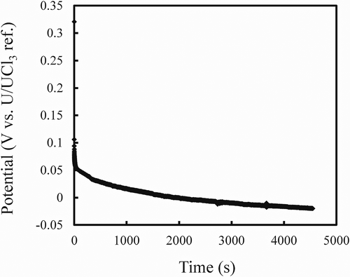
Electrorefining RUN1 was conducted with a liquid Cd cathode to demonstrate the grouped recovery of actinides from the fuel segments. shows the potential change of the liquid Cd cathode during the galvanostatic electrolysis at −20 mA (current density −31 mA cm−2 based on the inner diameter, 9 mm, of the alumina crucible for the liquid Cd cathode). The potential shifted toward negative values gradually. This indicated that the concentration of actinides in liquid Cd increased with the electrolysis time. The electrolysis was stopped when the total passed charge reached 91 C. This value corresponded to 0.94 at% of actinides recovered in liquid Cd assuming that the current efficiency would be 100%. The anode basket potential increased gradually with the electrolysis time and it was around 0.15 V at the end of RUN1, indicating that Zr dissolution from the fuel segments was limited at RUN1.
Figure 5. Potential change of the liquid Cd cathode during galvanostatic electrolysis at −20 mA (−31 mAcm−2).
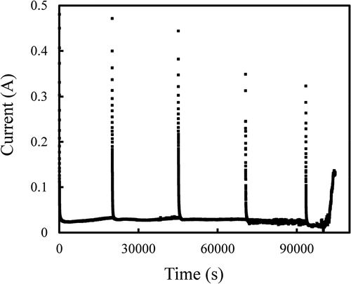
At electrorefining RUN2, an anodic potentiostatic electrolysis at 0.3 V was performed where a solid cathode was used to deposit U metal selectively. shows the current change of the anode. The electrolysis was temporary stopped for technical reasons. A large anodic current was observed just after the start of each electrolysis and then the current decreased to become stable at around 30 mA. Just before terminating the electrolysis, a sudden current increase was observed, implying the shift of the U/UCl3 reference electrode potential to the positive direction. The reason why the reference electrode potential shifted cannot be clearly explained. The development of a reference electrode, which is stable even at high radiation conditions, is a crucial issue for the future. The total passed electricity at RUN1 and 2 was 3190 C which corresponded to about 95% of the theoretical actinides dissolution ratio, ηtheo, defined as below,
3.2. ICP-MS analysis
All samples, fuel residues, Cd ingot, deposits on the solid cathode, bulk salts, and precipitate at the bottom of the crucible, were analyzed by ICP-MS. lists the ratio of the amounts of elements contained in each sample to their initial amounts in the fuel segments. The obtained results are described in detail in the following sections.
Table 2. Mass distributions of actinides and fission products at the electrorefining RUN1 and 2. Ratios of the amounts of the isotopes to their initial amounts (see ) are presented
3.2.1. Fuel residues
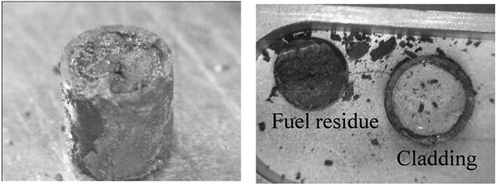
After RUN2, the fuel segments were recovered from the anode basket and the fuel residues were separated from the cladding (). Based on the ICP-MS analysis of the fuel residues, the remaining ratios of actinides (U, Pu, Np, Am, and Cm), Zr, Mo, Tc, noble metals (Rh, Ru, and Pd), and lanthanides (La, Ce, Pr, Nd, and Gd) were calculated,
Figure 7. Pictures of the fuel segment No. 1 recovered after the potentiostatic electrolysis (left) and the fuel residue separated from the cladding (right).
(Remaining ratio) = (Amount in fuel residues)/(Initial amount in fuel segments) × 100 (7)
Low remaining ratios of actinides and lanthanides, 0.5 ~ 4.3%, were obtained, while the remaining ratios of Zr (98.6%), Mo (87.9%), Tc (91.8%) and noble metals (88.1 ~ 104%) were found to be high. These results show that the dissolution of actinides and lanthanides in the melt leaving Zr and noble metals to a large extent in the anode was achieved in the present electrorefining RUNs. According to previous reports [Citation11,Citation13,Citation14,Citation22], the remaining ratio of noble metals is strongly correlated with that of Zr. A higher remaining ratio of noble metals is obtained at a higher remaining ratio of Zr, which was supported by the present results. It was noticed that alkali metals (Rb and Cs) and alkaline earth metals (Sr and Ba) were not found in the fuel residues, showing that all of them in the fuel segments dissolved into the melt.
3.2.2. Cd ingot and deposits on solid cathodes
After RUN1, the Cd ingot recovered from the liquid Cd cathode () was analyzed by ICP-MS. Based on the results, the separation factors defined as below were calculated,
where XM in Cd and XU in Cd are the concentrations of element M and 238U in the Cd, respectively, and XM in salt and XU in salt are the concentrations of element M and 238U in the salt, respectively. The calculated separation factors are listed in . The values obtained in the present study agreed reasonably well with the reported ones [Citation14,Citation23–Citation25] showing that actinides were successfully recovered in the Cd and separated from the fission products.
Table 3. Separation factors of actinides and lanthanides based on U. Evaluated values in this study and reported values in Refs [Citation14,Citation23–Citation25]
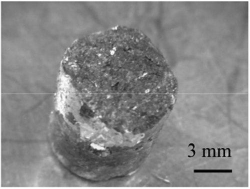
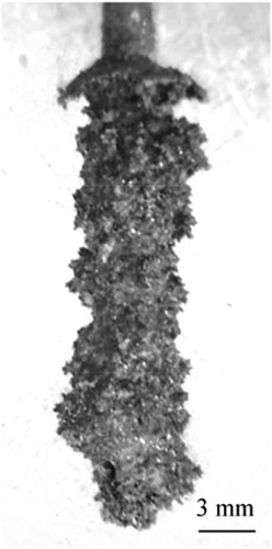
shows the deposit obtained on the solid cathode. The deposit was dendritic, which is typical for U metal deposition. The ICP-MS results showed that the solid cathode deposits were composed mostly of U (around 99 wt% of U). This confirmed the selective recovery of U on the solid cathode.
3.2.3. Salts
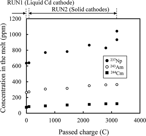
The concentrations (ppm by weight) of the actinides (U, Pu, Np, Am, and Cm) in the salts are plotted against passed charge in and . At RUN2, as expected, the U concentration decreased and TRUs (Pu, Np, Am, and Cm) concentrations increased as the passed charge increased, because U was recovered selectively on the solid cathodes as described in section 3.2.2.
Figure 10. Concentrations (ppm by weight) of 238U (○) and 239Pu (●) in the melt during the electrorefining.
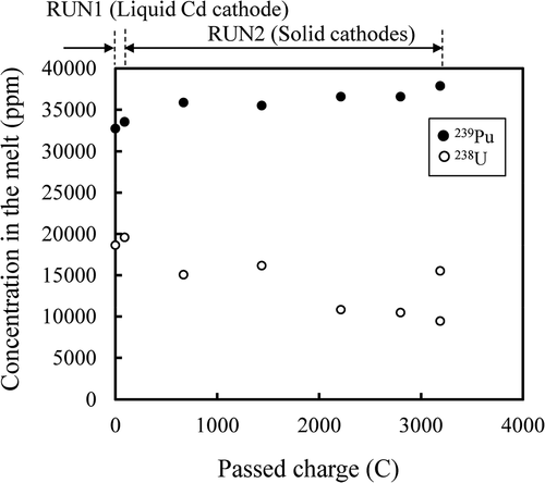
Figure 11. Concentrations (ppm by weight) of 237Np (●), 243Am (○) and 244Cm (■) in the melt during the electrorefining.
The concentrations of alkali metals (Rb and Cs) and alkaline earth metals (Sr and Ba) in the salt are plotted against passed charge in . There was no direct relationship between the concentrations and the passed charge observed: The concentrations increased initially and then did not seem to change significantly. This suggested that alkali metals (AL) and alkaline earth metals (ALE) dissolved by the chemical reaction with U3+ in the melt rather than electrochemically,
Figure 12. Concentrations (ppm by weight) of 138Ba (●), 135Cs (○), 88Sr (■) and 85Rb (□) in the melt during electrorefining.
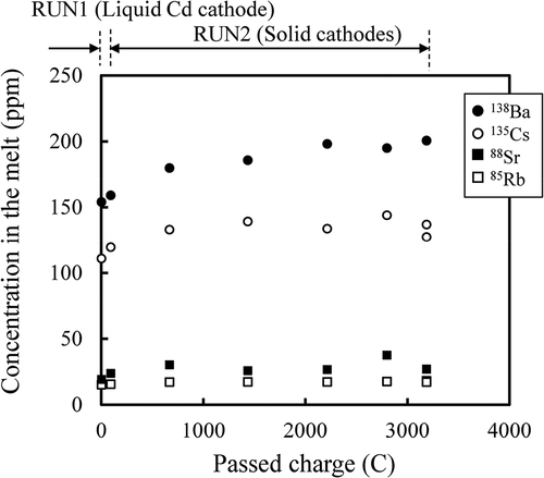
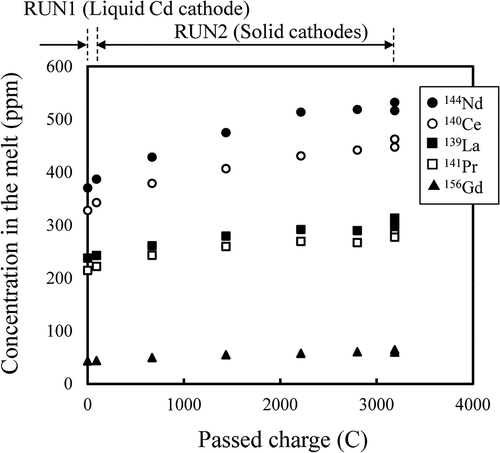
The behavior of lanthanides (La, Ce, Pr, Nd, and Gd) was similar to that of TRUs: The concentration increased with the progress of the electrorefining RUNs as seen in .
3.2.4. Precipitate at the bottom of the crucible
A salt sample taken at the bottom of the crucible after RUN2 contained a precipitate. The values seen in (E) were evaluated under the assumption that the precipitate would distribute homogeneously at the bottom of the crucible. It was confirmed that the precipitate contained U, possibly deposits dropped from the solid cathode rod during RUN2. Furthermore, a small amount of Zr, Mo, Tc, and noble metals (Rh, Ru, and Pd) were also found in the precipitate, thus likely also dropped physically from the anode [Citation11,Citation13,Citation14,Citation22]. Another possibility for the Zr accumulation at the bottom of the crucible was as follows: Since the actual anode potential was higher than the set potential, 0.3 V, due to the positive shift of the U/UCl3 reference electrode, Zr might have been dissolved electrochemically (reaction 5) at the last period of RUN2 and might have reacted with the U at the bottom of the crucible, in the fuel segments or on the solid cathode to form Zr metal according to reaction 11. Then, the formed Zr metal accumulated at the bottom.
3.2.5. Mass balance
As listed in , the mass balances of actinides (U, Pu, Np, Am, and Cm), lanthanides (La, Ce, Pr, Nd, and Gd), Zr, Mo, Tc, and noble metals (Rh, Ru, and Pd) were confirmed to be around 100%. 20–75% of the initial amount of alkali metals (Rb and Cs) and alkaline earth metals (Sr and Ba) in the fuel segments were detected only in the salt. Rest of these elements was possibly dissolved in the Na bond and transported to the fuel rod plenum due to the swelling of the fuel during the irradiation [Citation4–Citation9].
4. Conclusion
Electrorefining of irradiated metallic fuels (U-Pu-Zr-2MA-2RE, ~ 7 at% burn-up) was performed in LiCl-KCl melt at 773 K. The actinide recovery from the irradiated metallic fuel segments was successfully demonstrated and the behavior of actinides and fission products during the electrorefining were confirmed: Actinides and lanthanides in the irradiated metallic fuel segments were dissolved in the melt leaving Zr, Mo, Tc, and noble metals in the anode. Actinides were recovered in liquid Cd cathode with the separation factors similar to those obtained at the cold tests and experiments using the irradiated fuels of ~ 2.5 at% burn-up. U was selectively deposited on the solid cathode. Alkali and alkaline earth metals in the fuel segments were considered to dissolve by a chemical reaction with U3+ in the melt rather than electrochemically. The dissolved alkali and alkaline earth metals accumulated in the melt.
It was noticed that the aforementioned electrorefining behavior of actinides and fission products was similar to the case of electrorefining of the irradiated metallic fuel of lower burn-up (~ 2.5 at%) [Citation13,Citation14]. This indicated that the changes in the fuel structure, the actinides and fission products composition and the fuel matrix alloy phases induced by increasing burn-up from ~ 2.5 at% to ~ 7 at% had no significant effect on electrorefining.
It can be seen that the morphology of fuels with burn-up of 11 at% is not significantly different from ~ 7 at% [Citation5]. Thus, electrorefining would be expected to process fuels with a targeted burn-up of metal fuel sodium-cooled fast reactor concept, for example ~ 10 at% [Citation26], in a similar manner to the electrorefining presented in this study.
Acknowledgments
The authors wish to thank Messrs. H. Ohta, K. Nakamura, and T. Ogata (CRIEPI) for the information on the irradiated fuels and Messrs. V. Rondinella, D. Papaioannou, R. Nasyrow, R. Gretter, S. Van Winckel, and B. Lynch (JRC-KA) for the irradiated fuel fragments preparation and the analytical supports.
Disclosure statement
No potential conflict of interest was reported by the authors.
References
- Inoue T, Tanaka H. Recycling of actinides produced in LWR and FBR fuel cycles by applying pyrometallurgical process. Proc. Global 1997; 1997 Oct 5–10; Yokohama (Japan). p. 646–652.
- Iizuka M, Koyama T, Sakamura Y, et al. Development of pyro-processing technology at CRIEPI for carving out the future of nuclear fuel cycle. Proc. Global 2013; 2013 Sep 30-Oct 3; Salt Lake City (U.S.). Paper No. 7987.
- Mukaiyama T, Takizuka T, Mizumoto M, et al. Review of research and development of accelerator-driven system in JAPAN for transmutation of long-lived nuclides. Prog Nucl Energy. 2001;38:107–134.
- Ogata T. Metal Fuel. In: Konings RJM, editor. Comprehensive nuclear materials. Vol. 3. Amsterdam: Elsevier; 2012. p. 1–40.
- Ogata T, Kim YS, Yacout AM. Metal fuel performance modeling and simulation. In: Konings RJM, editor. Comprehensive nuclear materials. Vol. 3. Amsterdam: Elsevier; 2012. p. 713–753.
- Ohta H, Ogata T, Yokoo T, et al. Low-burnup irradiation behavior of fast reactor metal fuels containing minor actinides. Nucl Technol. 2009;165:96–110.
- Ohta H, Papaioannou D, Ogata T, et al. Postirradiation examinations of fast reactor metal fuels containing minor actinides -fission gas release and metallography of ~2.5at.% burnup fuels-. Proc. Global 2009; 2009 Sep 6–11; Paris (France). Paper No. 9241.
- Ohta H, Ogata T, Papaioannou D, et al. Development of fast reactor metal fuels containing minor actinides. J Nucl Sci Technol. 2011;48:654–661.
- Ohta H, Ogata T, Papaioannou D, et al. Irradiation of minor actinide-bearing uranium-plutonium-zirconium alloys up to ~2.5 at.%, ~7 at.%, and ~10 at.% burnups. Nucl Technol. 2015;190:36–51.
- Li SX, Johnson TA, Westphal BR, et al. Electrorefining experience for pyrochemical processing of spent EBR-II driver fuel. Proc. Global 2005; 2005 Oct 9–13; Tsukuba (Japan). Paper No. 487.
- Li SX, Simpson MF. Anodic process of electrorefining spent driver fuel in molten LiCl-KCl-UCl3/Cd system. Miner Metall Proc. 2005;22:192–198.
- Keiser DD Jr, Mariani RD. Zr-rich layers electrodeposited onto stainless steel cladding during the electrorefining of EBR-II fuel. J Nucl Mater. 1999;270:279–289.
- Murakami T, Kato T, Rodrigues A, et al. Anodic dissolution of irradiated metallic fuels in LiCl-KCl melt. J Nucl Mater. 2014;452:517–525.
- Murakami T, Rodrigues A, Ougier M, et al. Actinides recovery from irradiated metallic fuel in LiCl-KCl melts. J Nucl Mater. 2015;466:502–508.
- Ohta H. Private Communication.
- Kato T, Murakami T, Uozumi K, et al. Actinides recovery from irradiated MOX fuel by pyrochemical reprocessing. Proc. Global 2011; 2011 Dec 11–16; Makuhari (Japan). Paper No. 391320.
- Masset P, Bottomley D, Konings R, et al. Electrochmistry of uranium in molten LiCl-KCl eutectic. J Electrochem Soc. 2005;152(6):A1109–A1115.
- Iizuka M, Uozumi K, Inoue T, et al. Behavior of plutonium and americium at liquid cadmium cathode in molten LiCl-KCl electrolyte. J Nucl Mater. 2001;299:32–42.
- Koyama T, Iizuka M, Kondo N, et al. Electrodeposition of uranium in stirred liquid cadmium cathode. J Nucl Mater. 1997;247:227–231.
- Baboian R, Hill DL, Bailey R. A. Electrochemical studies on zirconium and hafnium in molten LiCl-KCl eutectic. J Electrochem Soc. 1965;112:1221–1224.
- Sakamura Y. Zirconium behavior in molten LiCl-KCl eutectic. J Electrochem Soc. 2004;151(3):C187–C193.
- Iizuka M, Omori T, Tsukada T. Behavior of U-Zr alloy containing simulated fission products during anodic dissolution in molten chloride electrolyte. J Nucl Sci Technol. 2010;47:244–254.
- Kinoshita K, Koyama T, Inoue T, et al. Separation of actinides from rare earth elements by means of molten salt electrorefining with anodic dissolution of U-Pu-Zr alloy fuel. J Phys Chem Solid. 2005;66:619–624.
- Kurata M, Sakamura Y, Hijikata T, et al. Distribution behavior of uranium, neptunium, rare-earth elements (Y, La, Ce, Nd, Sm, Eu, Gd) and alkaline-earth metals (Sr, Ba) between molten LiCl-KCl eutectic salt and liquid cadmium or bismuth. J Nucl Mater. 1995;227:110–121.
- Kurata M, Sakamura Y, Matsui T. Thermodynamic quantities of actinides and rare earth elements in liquid bismuth and cadmium. J Alloy Compd. 1996;234:83–92.
- Stauff NE, Ohgama K, Aliberti G, et al., Tradeoff analysis Of metal-fueled fast reactor design concepts. Proc. ICAPP 2017; 2017 Apr 24–28; Fukui and Kyoto (Japan). Paper No. 17207.

