
 ?Mathematical formulae have been encoded as MathML and are displayed in this HTML version using MathJax in order to improve their display. Uncheck the box to turn MathJax off. This feature requires Javascript. Click on a formula to zoom.
ABSTRACT
The uranium catalyst had been used in several industrial fields. The spent uranium catalyst became problematic radioactive waste awaiting a management strategy for the final disposal. This work studies a process to greatly reduce the volume of a spent uranium catalyst waste and the generation of a suitable waste form for final disposal. The process consists of several steps such as selective dissolution of the SiO2 catalyst support, precipitation of dissolved silicon followed by its purification for release, treatment of uranium-laden wastewater generated during the process, and immobilization of the final uranium-bearing astes for disposal. Based on bench scale-level experiments, the process was confirmed to be effective to reduce the volume of the uranium catalyst waste. The final volume reduction yield obtained in this work was over 80% from the volume of the initial uranium catalyst waste. The radioactivity of the secondary wastes, namely, the recovered silica and effluent generated from the process, was confirmed to be sufficiently managed for clearance with meeting the discharge criteria in Korea. The process could achieve the maximum volume reduction of the uranium catalyst waste to be transferred to a disposal site, with the by-products from the process being released, meeting discharge criteria in view of both nuclear and non-nuclear environmental regulations.
Introduction
Uranium (U) catalysts consisting of depleted uranium have been used for several purposes such as the production of acrylonitrile for the fabrication of synthetic fibers, destruction of volatile chloro-organic compounds, production of hydrocarbon compounds using synthesis gas, and so on [Citation1–Citation8]. The chemical form of these catalysts is typically a uranium-mixed metal oxide active phase impregnated on passive inorganic supports, such as SiO2 [Citation5–Citation8]. The catalysts are so chemically stable that it is hard to dissolve them in nitric acid or hydrochloric acid [Citation3,Citation8]. This poses a problem for the treatment and conditioning of such wastes prior to disposal.
Uranium catalyst wastes are usually stored at the site where they had been used while awaiting a management strategy before final disposal [Citation1,Citation3]. Depleted uranium is classified as low-level radioactive waste [Citation9]. Although the disposal route of radioactive waste varies depending on different circumstances within each country, its volume and associated disposal costs are anticipated to gradually increase over time, as the management of radioactive waste becomes severe in many countries [Citation10–Citation12]. It is not thought economical to recycle the depleted uranium component of the spent catalysts. Therefore, it is desirable to minimize the volume of these uranium-bearing wastes prior to disposal as much as possible.
A few companies in South Korea and Japan used a uranium catalyst to produce acrylonitrile for the fabrication of synthetic fibers, resulting in the generation of a large volume of problematic uranium catalyst waste [Citation3,Citation8]. Currently, research regarding the treatment of such spent uranium catalyst waste is scarce, and so far no treatment method has been proposed. This work describes a process to greatly reduce the volume of spent uranium catalysts prior to final disposal using the waste in South Korea as an example case.
Process for the volume reduction of spent uranium catalysts
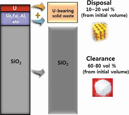
A private Korean company generated approximately 7,000 drums of spent uranium catalyst during production of acrylonitrile for the fabrication of synthetic fibers for 10 years until 2004 [Citation3,Citation13]. The spent uranium catalyst waste includes depleted uranium oxide (3 to 7 wt %, depending on the waste condition) mixed with several metal oxides such as antimony (Sb), iron (Fe) and aluminum (Al), all of which are impregnated into an SiO2 support (refer to and ). As mentioned, the treatment method of radioactive waste should be determined according to waste characteristics and the environment of country where the waste is generated. Disposal costs for low-level radioactive waste in Korea is very expensive, approximately US$ 12,500 per a drum of 200 l as of 2018. Therefore, finding a reliable and practical management strategy to reduce the volume of the uranium catalyst waste destined for final disposal is imperative.
Table 1. Concentration of major elements in solution after dissolution of the uranium catalyst waste in 4 M NaOH at 105°C for 2 h
Table 2. Changes of weight percentages of major element oxides in uranium catalyst measured by EDS, density, weight loss, and volume reduction after dissolution in 4 M NaOH at 105°C for 2 h
The disposal requirement for uranium-bearing waste to a low-intermediate level radioactive waste (LILW) repository operating in Korea is that ‘total radioactivity of alpha-emitting waste such as uranium waste should be less than 3,700 Bq/g with meeting several physicochemical properties for disposal’ [Citation14]. The specific radioactivity of the depleted uranium (U-234 of 0.001%, U-235 of 0.194%, and U-238 of 99.804%) used in the Korean catalyst is approximately 14,600 Bq/g. Selectively extracting only uranium portion from the uranium catalyst waste and disposing it to the site would result in a huge volume reduction, because the uranium portion is relatively much low in the uranium catalyst (refer to ). However, the radioactivity of the waste containing only uranium compound naturally exceeds the requirements for disposal at the LILW repository. On the other hand, if only the SiO2 of support of the uranium catalyst (it accounts for 70% of the uranium catalyst volume [refer to ]) is selectively extracted from the catalyst while the uranium remained in mixture of other metal oxide, and if the final uranium-bearing waste is disposed to the site, its radioactivity can meet the requirement, because the uranium is mixed with much of other non-radioactive metal oxides.
Accordingly, in order to reduce the volume of the catalyst waste while meeting radiochemical disposal requirements, we propose the selective removal of the SiO2 support while sentencing the remaining non-silicon components, including uranium, for disposal. This is to say, if the environmentally harmless silicon component used as the support of the catalyst is selectively eliminated from the spent uranium catalyst and is released to environment, and if the uranium-bearing waste remaining after removal of the support meets the acceptance criteria for the disposal site, the total volume of uranium-bearing waste to be transferred to the repository can be greatly reduced. In that case, the radioactivity of the subtracted silicon material from the catalyst should be low enough to meet the condition for free release to the environment (≤ 1 Bq/g). This concept is schematized in .
Figure 1. Concept of treatment of spent uranium catalyst with volume reduction for disposal.
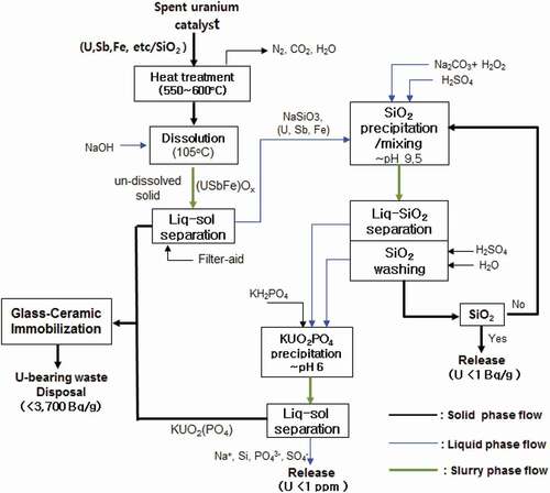
shows a process diagram that embodies the concept of and was determined on the basis of experimental trials for each step of the process in the laboratory. The process consists of several steps including the selective dissolution of the SiO2 support, precipitation of dissolved silicon ions accompanying its purification, treatment of uranium-containing wastewater generated during the process before its release, and immobilization of final solid uranium-bearing wastes suitable for disposal. In the event of receiving contaminated catalysts, a thermal pre-treatment step is required. Catalysts contaminated with complex carbon-nitrogen compounds, present due to side reactions during its use, for example, the production of acrylonitrile, are eliminated by heat treatment as determined through our preliminary experiments [Citation15,Citation16]. Based on our laboratory scale tests, the spent uranium catalyst, without such contamination, is first dissolved in an alkaline solution to selectively dissolve the SiO2 support part of the catalyst. The undissolved particles consisting mostly of uranium, antimony, and iron oxides are then separated from the solution. The separated solid waste is then sent to the immobilization step prior to its disposal. When the spent uranium catalyst is dissolved, uranium oxide of the catalyst is partially co-dissolved with the SiO2 (refer to ). The dissolved solution consisting of mostly silicon and a little uranium goes to the SiO2 precipitation step. Precipitation of the SiO2 is performed using pH-adjustment with sulfuric acid. Prior to the SiO2 precipitation, the feed solution is conditioned to convert uranyl hydroxyl ions (UO2(OH)xy-) in the alkaline solution into uranyl peroxocarbonate complex ion form (UO2(O2)(CO3)24-), which exhibits very high solubility, by adding carbonate and hydrogen peroxide to the solution before its pH adjustment. This retained the uranium ion in solution preventing it from being incorporated into the SiO2 precipitate. The precipitated SiO2 is separated from the solution followed by in-situ washing with acid and water in order to purify the precipitate in order to meet the radiochemical clearance criteria before its release to the environment. If the precipitated SiO2 is not washed enough to meet the clearance level, the precipitated SiO2 can be re-dissolved and re-precipitated with the same procedure. The uranium radioactivity of solid waste for clearance in Korea is required to be less than 1 Bq/g. All the wastewater from the SiO2 precipitation step is to be sent to the uranium precipitation step where uranium in solution can be precipitated in the form of KUO2PO4. Precipitated uranium solid particles are separated from solution. Then, the separated KUO2PO4 waste is mixed together with the undissolved material separated from the earlier dissolution step. The uranium concentration of liquid waste to be released to environment is required to be below 1 ppm. All the solid uranium-bearing waste generated in the process is immobilized by sintering with mixing with a glass fluxing agent to form a glass-ceramic composite matrix. Immobilization technologies carried out at high temperature, such as ceramization and glassification, are known to reduce volume of the waste form [Citation17].
Figure 2. Process suggested in this work for volume reduction of uranium catalyst waste.
The conditions used at each step of the process in were determined based on many preliminary experiments and chemical knowledge identified at each step [Citation15,Citation16]. The main objective of this work was to verify and evaluate the process developed through bench-scale level experiments using optimal conditions already obtained at each step of the process rather than detailed discussion of chemical behavior of related elements at each step of the process. As the requirement for a thermal pretreatment process is reserved only for those wastes that are contaminated, such a process falls outside the scope of this paper, and it will not be further discussed. A full description of the spent catalyst and pretreatment steps taken has been previously disseminated [Citation15,Citation16]. The characteristics and performance of each step of the process, after pretreatment, will be discussed.
Experimental
The uranium catalyst waste used in this work was obtained from a Korean company (Taekwang Industrial Co. Ltd located in Ulsan in Korea). Its composition and morphology were measured by a Scanning Electron Microscopy with Energy dispersive X-ray Spectroscopy (SEM-EDS) (Bruker Namo, Xflash Detector 410-M) (refer to and ). When the uranium catalyst waste was contaminated with some tar-like material, it was heat-treated before its dissolution according to the process suggested in . The contaminant material was confirmed to be mostly removed by heat treatment around 550°C to 600°C [Citation15].
Figure 3. Change of uranium and silicon ion concentration with pH in solution after dissolving UO2 (NO3)6H2O in nitric acid and sodium silicate in NaOH.
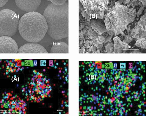
Figure 4. SEM-EDS micrograph and map of element distribution on the catalyst surface before (A) and after (B) the dissolution.
To evaluate the solubility behavior of uranium and silicon that were the major important elements in the uranium catalyst, their solubilities were measured in the pH range between 1 and 14. For that, UO2(NO3).6H2O and sodium silicate salt were sufficiently dissolved in 1 M nitric acid and in 2 M NaOH in beakers until their supersaturation in the solution, respectively. Then their solutions were pH-adjusted with NaOH and/or HNO3. When the desired pH was reached, the solution was kept without mixing for 1 h. Then the supernatant in the beaker were taken and analyzed.
The uranium catalyst waste without such a contamination was directly dissolved in a 4 M NaOH solution at a ratio of 5 mL of solution per g of solid. A mass of 600 g uranium catalyst waste powder and 3 L of NaOH solution were put into a Teflon-coated dissolver (made of stainless steel 304L) of 10 L. The dissolution was carried out at 105°C for 2 h with mixing. The SiO2 support was dissolved as a sodium silicate solution, called water glass. Uranium and other metal oxides from the uranium catalyst were also partially co-dissolved together with silica according to their solubilities under strong alkaline conditions (refer to ). The undissolved particle-solution slurry after dissolution was pumped into a filter press system (Korea Filter Co. Ltd., 250MM 4 CH) equipped with a polypropylene filter cloth (25 cm x 25 cm) of 0.5 μm pore size for solid-liquid separation. A porous diatomite powder of mainly silica (ParaTom Co., KD801) was used as a filter-aid in the filter press system to enhance the separation efficiency of ultra-fine particles and to protect the filter cloth from the fine particles blocking it [Citation18–Citation20]. The filter-aid was coated on the filter cloth to a thickness of approximately 1.5 mm in advance. The volume change of the catalyst by dissolution was evaluated using the weight change of the catalyst, and tap densities of initial uranium catalyst powder and undissolved particles.
The sodium silicate solution separated from the above filtration went to a SiO2 precipitation tank of 20 L where its pH was controlled to around 9.5 with a 1 M H2SO4 solution. In this step, the uranyl hydroxyl ion in solution was first converted to the uranyl peroxocarbonate complex ion [Citation21], the solubility of which is very high, in order to restraining the uranyl ions from entering into the SiO2 precipitate. For that, the sodium silicate solution was first adjusted to have 0.45 M H2O2 and 0.025 M Na2CO3 and then was pH adjusted. A slurry of particulate silica-aggregated clusters was formed during the pH adjustment. The slurry was transferred into another filter press system with 10 channels of 20 cm x 20 cm filter plate) (Korea Filter Co. Ltd., 200MM 10 CH) and squeezed to form a SiO2 cake [Citation22,Citation23]. The filter-aid was not required at this step. To remove residual uranium from within the SiO2 cake, the cake was washed in-situ by passing each 3 L of 0.5 M H2SO4 solution and 3 L of water into the filter press system sequentially. After circulating them in the system for 5 min, the cake was then discharged from the system. The radioactivity of the recovered SiO2 cake was analyzed to evaluate whether the SiO2 cake meets the required release criteria for clearance.
All the solutions from the silica recovery step were collected in a tank (20 L) as an effluent treatment step. To remove uranium from the final solution, the solution was dosed with KH2PO4 to have 1 or 2 mM of PO43- and was pH adjusted in the range between 6 and 6.5 and then left to stir for 2 h. The uranyl ion in the solution was precipitated in the form of KUO2PO4. The uranium concentration of supernatant was analyzed to evaluate whether the solution meets environmental release requirements ([U] ≤ 1ppm).
The undissolved solids from the dissolution step and the uranyl phosphate solid from the effluent treatment step were mixed for immobilization and final disposal. The solid slurry was dried, and then B2O3, as a glass flux agent, was added into the powder to obtain a weight percentage ratio of SiO2 to B2O3 of 5:1. The SiO2 component in the solid slurry to be immobilized came mostly from the filter aid of diatomite used in the filter press and partially from the undissolved slurry where little SiO2 still remained even after the dissolution step. The prepared powder was pressed at 20 MPa in a mold to make a green followed by sintering it at 1,100°C for 4 h. The immobilized material with a glass-ceramic composite matrix was finally made. The compressive strength, sintering shrinkage, and uranium leachability of final sintered pellets were analyzed. Waste form shrinkage was measured through apparent volume change, and the leachability was evaluated according to ASTM-C-1285 method for product consistency test.
All the chemicals used in this work were reagent grade and used as received. All the elemental concentrations in solutions handled in this work were analyzed by an Inductively Coupled Plasma Optical Emission Spectrometer (ICP-OES) (Analytikjena PQ9000 Elite). The radioactivity of uranium in the silica cake to be disposed was measured by an α-spectrometer (Alpha Analyst, CANBERRA) according to ASTM 1345–08. The particle sizes of uranium catalyst before and after the dissolution were measured by a particle size analyzer (Microtrac, S3000).
Results and discussion
Dissolution and separation of undissolved particles
The main purpose of the process in is to achieve the maximum volume reduction of the uranium catalyst waste to be transferred to a disposal site, with the by-products (e.g. SiO2 cake from the catalyst and wastewater) from the process being released, meeting discharge criteria in view of both nuclear and common environmental regulations. For that, selective dissolution of SiO2 from the catalyst was first required with minimal dissolution of the other major metal oxides (e.g. U, Sb, Fe). Silica is known to be readily soluble in strong alkaline solution (pH> 12) at elevated temperature [Citation24]. The exact mechanism of dissolution of SiO2 is complicate, but it is known that the silica surface first reacts with water to form silicic acid, SiOx(OH)4-2x, which is consecutively attacked by NaOH to form various sodium silicates (called water glass) usually written as SiO32-, Si2O52-, Si3O72- anion forms [Citation25–Citation28]. The dissolution reaction can be simply expressed according to equation (1).
Uranium and Fe oxides are much more soluble in acid rather than in base [Citation29], while Sb oxide is soluble in both acid and base [Citation29,Citation30]. To more concretely understand the behavior of uranium during SiO2 dissolution, and its precipitation with changing pH, the solubilities of uranyl and silicon ions were measured with a change of pH. They are shown in . The results were comparable to those solubilities published in the previous papers [Citation31–Citation34]. Silicon showed a very high solubility of approximately 40,000 ppm at 2 M NaOH, but the solubility dropped rapidly to approximately 150 ppm below pH 11. Uranium solubility was observed to be approximately 2,200 ppm at 2 M NaOH with the lowest concentration, approximately 0.003 ppm, at pH 7. Uranium is known to be present as anionic species, UO2(OH)3−, UO2(OH)42-, and so on in alkaline solution [Citation34].
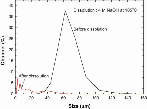
The spent uranium catalyst was dissolved in a 4 M NaOH solution at 105°C to evaluate the dissolution step of the process of . The NaOH concentration was chosen with consideration for the dissolution yield and rate through our preliminary experiments [Citation15,Citation16]. shows the concentrations of dissolved elements extracted from the catalyst. The Si concentration was 42,690 ppm. However, the concentration of U was 470 ppm, lower than the solubility of uranyl ion at pH 14 in . That is considered to be because the amount of uranium dissolved from the uranium catalyst, where the UO2 strongly was bounded with other metal oxides, in 2 h was smaller than the solubility value at equilibrium. Other metals, namely, Fe, Mo, and V oxide, were dissolved reaching an approximate concentration of 100 ppm, but Sb oxide was easily dissolved and found to be at a concentration of 1,900 ppm. shows the change of weight percentages of major element oxides in uranium catalyst waste before and after its dissolution. It was evaluated using atomic percentages of major elements, which was measured by the EDS, with assumption that Si, U, Sb, and Fe in the uranium catalyst exist in the forms of SiO2, UO2, Sb2O3, and FeO, respectively. Also shows the tap densities of the initial uranium catalyst and the undissolved material from the catalyst and changes of weight and volume of the undissolved material after the dissolution, which were measured through experiments. Approximately 97.4% of silica component in the catalyst was removed. On the contrary, the weight percentages of U, Fe, and Sb oxides greatly increased, because the dissolution selectively removed most of Si component rather than other metal components from the catalyst. It means that the support of SiO2 of the uranium catalyst was selectively dissolved in the alkaline solution. Approximately 40% of the initial uranium catalyst weight decreased corresponding to a volume reduction of approximately 70% the initial uranium catalyst volume. This was determined by using weight change and tap densities of samples before and after the dissolution. The tap density of undissolved solid was 2.1 g/mL, while the initial one of initial uranium catalyst was 1.06 g/mL. The oxides of U, Fe, and Sb, which were much less undissolved, possess relatively higher densities than the support SiO2, in part due to the support of catalyst containing micro pores.
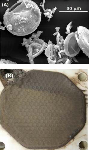
shows the SEM-EDS micrograph and elemental distribution map of major elements on the catalyst surface before (A) and after (B) the dissolution. The initial uranium catalyst was spherical with a uniformed macrostructure but uneven surface. The catalyst components of U in blue, Sb in green, and Fe in cyan were observed to be relatively homogeneously distributed across the SiO2 support in . Following the dissolution, signals corresponding to Sb and U became dominant because most of the Si was leached out. As the SiO2 support was dissolved into solution, the catalyst collapsed into smaller particles of undissolved materials. A range of fine particles was also observed. The lump-like particles in SEM photograph of were formed during drying of the undissolved particles obtained after dissolution. shows the change in particle sizes of the uranium catalyst before and after the dissolution. The initial uranium catalyst had a mean number size of 52.6 μm in a unimodal distribution. In contrast, the undissolved particles after the dissolution had a size of 2.8 μm in a multi-modal distribution including fine particles of less than 1 μm.
Figure 5. Size distributions of particles of uranium catalysts before and after dissolution.
The slurry containing the undissolved particles from the dissolution step was separated into solid and liquid by a filter press system. As mentioned above, the slurry included a lot of fine particles including those less than 1 μm. Such undissolved fine particles in the slurry were very hard to be effectively separated from the solution. The ultra-fine particles easily blocked the pores of the filter cloth used in the filter press, thus reducing separation efficiency. When the sodium silicate solution from the dissolution step was cooled, it became viscous because of polymerization of sodium silicate species in alkaline media [Citation35]. This also made it more difficult to separate the particles from the solution. To effectively separate such fine undissolved particles from the solution, a filtration system equipped with a filter cloth where a filter-aid was precoated before the separation of slurry was used. Figure S1 shows the mechanism of filter-aid precoating on to the filter media of filter press system. The filter-aid used was a diatomite (SiO2 90.1%, Al2O3 3.8%, Fe2O3 1.3%, K2O+ Na2O 2.5%) powder with a lot of fine pores as shown in . The mean size of the filter-aid powder was 10.5 μm. Usage of the filter-aid is known to protect the septum, filter cloth, from fine particles or gelatinous particles blocking the filter cloth [Citation18,Citation20,Citation36]. The solution could pass through the void within filter-aid layer and the fine pores of diatomite particles. When the filter-aid was used with a coating of about 1.5 mm in thickness on the filter cloth, the separation of the slurry was successful with the formation of a rigid filter cake within each cell of the filter press, as shown in . The filter-aid remained as a part of the separated cake of uranium-bearing waste thus causing an increase of about 10% in the waste volume for disposal, compared with only the volume of undissolved materials left just after the dissolution. However, the filter-aid material included in the cake of undissolved particles would be used as a glassification material for immobilization of undissolved materials, which will be discussed more in detail later.
Figure 6. SEM photograph of diatomite used as a filter-aid (A) and photograph of cake of undissolved particles made in a filter press system using filter-aid (B).
Precipitation of silica and its purification
The sodium silicate solution separated from the slurry went to the SiO2 precipitation step in . The pH adjustment of the solution was done between 9 and 10 with sulfuric acid to precipitate silicon from solution as SiO2. The precipitation mechanism of SiO2 from silicate solutions is known to have a syneresis process through polymerization of monomeric silicic acid, their aggregation, and gelation [Citation22,Citation23,Citation37]. The precipitation reaction can be simply expressed as follows.
The sodium silicate solution was found to contain some uranyl hydroxyl ions. Therefore, when the solution is pH adjusted to below pH 10, uranium in the solution is precipitated as uranium hydroxide, as expressed in . This causes contamination of the recovered SiO2 cake with uranium, which makes the clearance of the SiO2 difficult. To suppress the entrainment of uranium species into the SiO2 precipitate as low as possible, the uranyl ion species was retained in the solution during the SiO2 precipitation. For that, the uranyl hydroxyl ion with a very low solubility at the pH required for SiO2 precipitation needed to be converted to different uranyl species with a higher solubility. The uranyl hydroxyl ion is known to form a charged uranyl peroxocarbonate complex, UO2(O2)(CO3)24-, under alkaline conditions in the presence of carbonate and hydrogen peroxide according to equation (3). The uranium complex is known to have a very high solubility in alkaline conditions [Citation21,Citation38]. Also, the adsorption of such a uranium anion complex onto the SiO2 precipitate particle surface is considered restrained due to an electrical repulsion between the anion and particles of SiO2 formed in the solution. This is because the SiO2 particle surface has a very high negative zeta potential of approximately −70 mV over pH 8 [Citation39].
To confirm the prevention of uranium entrainment into the SiO2 precipitate is possible, a set of SiO2 precipitation tests were conducted using a sample of the catalyst dissolved solution with initial concentrations of U 106.6 ppm and Si 15,980. The solution was conditioned in three ways. The first was only pH adjusted to 9.5. The second was dosed with Na2CO3 to a concentration of 0.05 M, before the same pH adjustment. In the third, both Na2CO3 and H2O2 were added to the solution to reach concentrations of 0.05 M and 1 M, respectively, before the same pH adjustment. The remaining concentrations of U and Si were measured in the supernatant after the SiO2 precipitation. The results are displayed in . In all the cases, over 99% of the Si was precipitated as SiO2. It means that the SiO2 precipitation was hardly affected by the existence of carbonate and hydrogen peroxide in the solution. The behavior of U in the solutions, however, was quite different. In the solution in which only the pH was adjusted approximately 99% of U was precipitated from solution as uranyl hydroxide, as explained in . When the carbonate was added to the solution followed by the pH adjustment, the U precipitation decreased a little because of the formation of the uranyl tri-carbonate complex UO2(CO3)34-. The solubility of this is much higher than that of uranyl hydroxide in alkaline conditions [Citation40]. When the uranyl ion was converted to uranyl peroxocarbonate complex ion, approximately 74% of initial uranium remained in the supernatant solution during the SiO2 precipitation. These results show that the pH adjustment accompanying conditioning of the solution matrix with carbonate and hydrogen peroxide is effective for prevention of entrainment of uranium species into SiO2 precipitate.
Table 3. Remaining percentages of U and Si in the supernatant with a change of solution matrix for SiO2 precipitation using a uranium-catalyst dissolved solution with U of 107 ppm and Si of 15,980 ppm
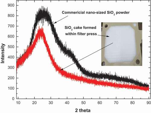
Even if such a method to deter uranium-contamination of the SiO2 is used, the final SiO2 precipitate is to be contaminated by the uranium-containing supernatant as the supernatant solution remains in voids formed between the SiO2 precipitate particles. Thus, the SiO2 precipitate to be released for clearance should be washed and purified. This procedure is taken into account in the process scheme of . The washing was carried out by passing water and 0.5 M H2SO4 solution through the SiO2 precipitate cake. When the obtained SiO2 cake was not sufficiently washed, the purification was carried out by re-dissolution of the precipitated SiO2 followed by its re-precipitation to SiO2 with the same procedure as that in the first precipitation stage. The SiO2 precipitate was easily dissolved again in 1 to 2 M NaOH at 60 to 80°C forming a fresh sodium silicate solution. shows the XRD pattern of the SiO2 cake finally obtained from the filter press. It showed the XRD pattern of amorphous SiO2 similar to that of a commercial nano-sized SiO2 powder, which is similar to previous reports [Citation26,Citation41]. The SiO2 cake made (as shown as an inset photo in ) in the filter press in the case without the purification had a radioactivity of 3.45 Bq/g of uranium. However, after a single purification cycle, the radioactivity greatly decreased to 0.56 Bq/g, which sufficiently meets the clearance criteria of 1 Bq/g as guided by IAEA [Citation42]. The result shows that the SiO2 precipitate cake generated in this process can be purified sufficiently for release to the environment.
Figure 7. XRD patterns of SiO2 precipitate cake (inset photograph) formed in a filter press in this work and commercial nano-sized SiO2 powder.
Treatment of process wastewater
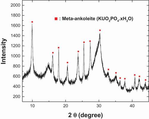
All the solutions generated during the process should also be decontaminated before release to meet the regulation for drainage of wastewater (below 1 ppm uranium in Korea) [Citation43]. There are several ways to remove uranium from wastewater. Based on our preliminary tests [Citation16], a way to quickly and effectively remove uranium from solution as uranyl phosphate, such as MUO2PO4·nH2O (M = Na+, K+, NH4+), was chosen because such uranium compounds have very low solubilities [Citation32,Citation44,Citation45]. The KUO2PO4 precipitation occurred according to equation (4).
shows the initial concentrations of elements in the final wastewater to be treated by the KUO2PO4 precipitation. The uranium concentration was approximately 40 ppm, much lower than that in the initial dissolution solution (see ). This is because of the dilution of the initial dissolution solution due to the increase of solution volume by the pH adjustment, washing, and purification steps mentioned above. Our preliminary pH screening identified the pH window of 6.0 ~ 6.5 with lowest solubility of KUO2PO4 [Citation16], which is supported by literature [Citation32,Citation44]. The pH of 6.25 was finally selected for this work. shows the changes of U, Sb, and Si concentrations in solution during precipitation with using 1 mM and 2 mM KH2PO4. The uranium was observed to be quickly removed from solution by the KUO2PO4 precipitation with the remaining concentration falling below 0.1 ppm within a few minutes in both cases of using 1 mM and 2 mM KH2PO4. The case using 2 mM KH2PO4 was the faster and reached the detection limit of the ICP-OES used within 5 min, corresponding to a decontamination factor of approximately 8,000. Negligible changes to the concentrations of Si, Sb, and the other major elements in the solution besides uranium were observed during the precipitation, which means that the precipitation system could selectively remove the uranium from the solution. shows the XRD result of KUO2PO4 formed in . The mean size of KUO2PO4 particles formed in using 1 mM and 2 mM KH2PO4 were 31.7 μm and 23.5 μm, respectively. The particles were confirmed to be effectively separated from the solution by a filter press without using the filter-aid. Figure S2 shows a photograph of the KUO2PO4 particle cake formed on cloth media in a filter press system.
Table 4. Initial concentrations of major elements in solution for KUO2PO4 precipitation
Figure 8. Changes of U, Sb, and Si in solution with time during the KUO2PO4 precipitations at pH 6.25 with using 1 mM and 2 mM KH2PO4.
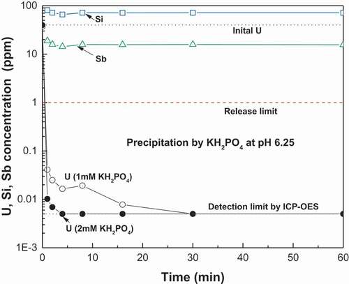
Figure 9. XRD patterns of KUO2PO4 precipitate formed in a solution with 1 mM KH2PO4 at pH 6.25.
Immobilization of final uranium-bearing wastes generated during the process
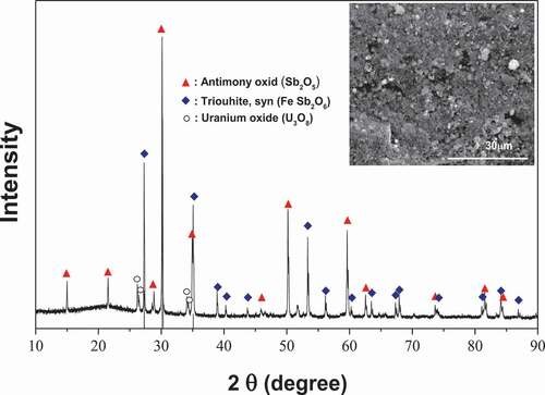
The undissolved solid material from the dissolution step and the uranyl phosphate precipitate from the wastewater treatment step both require immobilization before final disposal. The components included in the target uranium-bearing waste are shown in . The most dominate components were antimony and uranium by weight. The Si component was mostly from the filter aid of diatomite used in the filter press. Sodium was from residual of the water glass made during the dissolution of the catalyst support, and K and P were from the KUO2PO4. The silicon oxide can be a glass network former [Citation46]. Sb and Fe oxide can become glass components as well [Citation44–Citation49]. When a glass flux agent such as Na2O or B2O3 is added into such a waste, it modifies the glass former Si oxide to make soda-lime or borosilicate glasses when thermally treated at or above the glass forming temperature [Citation46,Citation50]. On the other hand, the U oxide has a higher refractory character, and so it does not become a glass at the sintering temperature used in this work. To make an immobilization matrix with a glassy phase of a defined shape, the powdered mixture of waste and additives were first compacted to make a green body and then sintered at an elevated temperature before the melting temperature of the refractory component. The sintered material became a glass-ceramic composite matrix [Citation17]. Such a glass-ceramic immobilizes the refractory phase of uranium and other oxides by direct incorporation of them into the glass or ceramic structure or by encapsulation of them by the glassy phase. Such a sintering process is usually accompanied by a volume reduction of the waste due to the loss of voids within waste during melting of the glass phase and partial coalescence of refractory particles [Citation49–Citation52]. In this work, B2O3 was chosen as a glass flux to form borosilicate glass phase in the sintered body, taking into consideration of the our preliminary experiments [Citation16] that showed that the property of immobilized material with borosilicate glassy phase was better than that of immobilized material with soda-lime glassy phase made by using Na2O. The B2O3 was added into the uranium-bearing waste powder with a ratio of B2O3 to SiO2 existing in the target material (based on the result of ), 20 wt% to 80 wt% according to general ratio of the components to form borosilicate glass phase [Citation46]. Then, the mixture was pressed at 20 MPa to make green pellets, and the pellets were sintered. shows the XRD result of the sintered material (shown in the inset SEM photo). The uranium-bearing waste powder was observed to be encapsulated within the glass phase. The XRD results show that the sintered matrix has an amorphous pattern due to the glass phase and crystalline structure due to the uranium and antimony oxides at the same time, which is a typical XRD pattern of glass-ceramic composition matrices [Citation53]. The densities of materials at each step for the immobilization are shown in . The density of the finally immobilized pellet increased about five fold, compared to that of initial uranium catalyst powder. The compressive strength and uranium leachability of the prepared sintered material were 65.3 MPa, and 6.24x10⁻⁴ g/m2⋅day, respectively. The volume of the green body decreased by 54.5% after sintering. Taking into consideration the volume reduction following sintering, the final volume reduction of the immobilized solid waste to be disposed of is 82% with respects of initial volume of uranium catalyst waste.
Table 5. Concentrations of elements included in U-bearing waste to be immobilized
Table 6. Densities of samples at each step for immobilization
Figure 10. XRD pattern of immobilized material (inset photograph) after sintering mixture of the uranium-bearing waste and B2O3 at 1100°C.
Conclusions
All the steps of the process suggested for the volume reduction of the uranium catalyst waste were tested and evaluated. Approximately 94% of the SiO2 support of the catalyst was extracted in a form of sodium silicate by alkaline dissolution. The dissolved silicate was recovered as a silica cake and purified in a filter press while meeting the condition for clearance of below 1 Bq/g. The addition of phosphate for the precipitation of uranium as KUO2PO4 was fast and efficient to treat the wastewater generated from the process, meeting the condition for release to the environment of below 1 ppm of uranium. All the solid wastes coming out of the process can be immobilized as a strong and stable glass-ceramic matrix with a high compressive strength of more than 60 MPa and a low uranium leachability of 6.24x10⁻⁴ g/m2·day. Those values far exceed the immobilization requirement for disposal of low and intermediate radioactive waste in Korea, which are more than 3.44 MPa and 6 for compressive strength and for Cumulative Fraction Leached (CFL) value, respectively [Citation43,Citation54,Citation55]. The final volume reduction yield of the immobilized waste was over 80% with respects to the volume of initial uranium catalyst waste. Based on all the experimental results obtained during bench scale testing, the process suggested in this work was confirmed to be effective for the volume reduction of the spent uranium catalyst.
Supplemental Material
Download MS Word (314.8 KB)Acknowledgment
This work was supported by the National Research Foundation of Korea (NRF) grant funded by the Korea government (MSIP) [NRF-2017M2A8A5015147].
Disclosure statement
No potential conflict of interest was reported by the authors.
Supplementary material
Supplemental data for this article can be accessed here.
Related Research Data
References
- NEA/OECD report, Management of depleted uranium, 2001
- Dua S, Burleigh MC, Haire MJ, et al. Putting depleted uranium to use: a new class of uranium-based catalysts. Tucson (AZ): Waste Management 2001 Symposium; 2001.
- Sugai H, Management of wastes-containing radioactive materials in nuclear and conventional industries. Proceeding of International Symposium on EcoTopia Science 2007, ISETS07, 2007
- Kerry T, Amphlett J, Reddy A, et al. The removal of uranium from spent uranium catalyst effluent using ion exchange resins. Global 2017, Seoul. 2017.
- Hutchings GJ, Heneghan CS, Hudson ID, et al. Uranium-oxide-based catalysts for the destruction of volatile chloro-organic compounds. Nature. 1996;384(28):341–343.
- Chang -C-C. Studies of the Fischer-Tropsch process on uranium catalyst. Inorg Chim Acta. 1984;94:259–262.
- Ismagilov ZR, Kuntsevich SV. Catalyst containing depleted uranium compounds. Chem Sustainable Dev. 2009;17:439–463.
- Sawada K, Hirabayashi D, Enokida Y. Reaction of antimony-uranium composite oxide in the chlorination treatment of waste catalyst, waste management 2013. Phoenix (AZ): Waste Management; 2013.
- US DOE report, DOE/Em-0654 Rev 4. United States of America fifth national report for the joint convention on the safety of spent fuel management and on the safety of radioactive waste management national report, 2014
- Song J-S, Kim Y-K, Lee S-H. A pre-study on the estimation of NPP decommissioning radioactive waste and disposal costs for applying new classification criteria. J Nucl Fuel Cycle Waste Technol. 2015;13(1):45–53.
- NEA/OECD report, low-level radioactive waste repositories: an analysis of Coats, 1999
- US NRC report, waste burial charges. NUREG-137 Rev 16, 2010
- Kim K-W, Lee E-H, Lee K-Y, et al. Patent 9,181,605 B2, 2015.
- Kim B, Kim C-L. Review of the acceptance criteria of very low level radioactive waste for the disposal of decommissioning waste. J Nucl Fuel Cycle Waste Tech. 2014;12(2):165–169.
- Kim K-W, Kim M-J, Oh M-K, et al. Volume reduction of uranium catalyst waste for final disposal, Eurasia 2018 waste management symposium proceeding. Istanbul; 2018.
- KAERI report KAERI/RR-4271/2017. Development of technology for volume reduction of depleted uranium waste, 2017.
- Donald W, Metcalfe BL, Taylor RNJ. Review the immobilization of high lever radioactive waste using ceramics and glass. J Mat Sci. 1997;32:5851–5887.
- Schiller S, Schmidem HJ. Ultrafine dust filtration using precoat materials considering the influence of filter media. Chem Eng Tech. 2014;37(6):1009–1020.
- Rilling K. Precoat filter aids can reduce wastewater treatment costs. Environ Sci Eng Magazine. 2014 Nov/Dec;12–14.
- Kuhn M, Briesen H. Dynamic modeling of filter-aid filtration including surface- and depth-filtration effects. Chem Eng Tech. 2016;39(3):425–434.
- Kim K-W, Lee K-Y, Chung D-Y, et al. Evaluation of the stability of uranyl peroxo-carbonato complex ions in carbonate media at different temperatures. J Hazard Mater. 2012;33–234:213–218.
- Brinker CJ, Scherer GW. Sol-gel science the physics and chemistry of sol-gel processing. San Diego (CA): Academic Press, Inc; 1990.
- Wilhelm S, Kind M. On the relation between natural and enforced syneresis of acidic precipitated silica. Polymer. 2014;6(12):2896–2911.
- Niibir Y, Kunita M, Tochuyama O, et al. Dissolution rates of amorphous silica in highly alkaline solution. J Nucl Sci Tech. 2000;37:349–357.
- Fertani-Gmati M, Brahim K, Khattech I, et al. Thermochemistry and kinetics of silica dissolution in NaOH solutions: effect of the alkali concentration. Thermochim Acta. 2014;5944:58–67.
- Patel BH, Patel PN. Synthesis and application of nano-sized SiO2 to textiles: a review. Ma: International Dyer; 2012. p. 35–39.
- Helmuth R Alkali-Silica Reactivity: an overview of research, strategic highway research program report shrp-c-342, 1993.
- Jendoubi F, Mgaidi A, Maaoui EL. Kinetics of the dissolution of silica in aqueous sodium hydroxide solutions at high pressure and temperature. Canadian J Chem Eng. 1997;75:721–727.
- Baes CF Jr., Mesmer RE. The hydrolysis of cations. Florida: Robert E. Krieger Pub. Co; 1986.
- Hashimoto H, Nishimura T, Umetsu Y. Hydrolysis of antimony(III)-hydrochloric acid solution at 25°C. Mater Trans. 2003;44(8):1624–1629.
- Alexpander GB, Heston WM, Iler RK. The solubility of amorphous silica in water. J Am Chem Soc. 1958;58:453–455.
- Lewis DG, Burms PC, Fein JB. Review of uranyl mineral solubility measurements. J Chem Thermodyn. 2008;40:335–352.
- Kalin M, Wheeler WN, Meinrath G. The removal of uranium from mining waste water using algal/microbial biomass. J Environ Radioact. 2005;78:151–177.
- Casas I, De Pablo J, Gimenez J, et al. The role of pe, pH, and carbonate on the solubility of UO2 and uraninite under nominally reducing conditions. Geochim Cosmochim Acta. 1998;62(13):2223–2231.
- Tognonvi M, Rossignol S, Bonnet J-P. Physical-chemistry of sodium silicate gelation in an alkaline medium. J Sol-Gel Sci Technol. 2011;58:625–635.
- Rilling K. Precoat filter aids can reduce wastewater treatment costs. Environ Sci Eng Magazine. 2013 Nov/Dec;12–14.
- Wilhelm S, Kind M. On the relation between natural and enforced syneresis of acidic precipitated silica. Polymer. 2014;6:2896–2911.
- Kim K-W, Chung D-Y, Yang H-B, et al. A conceptual process study for recovery of uranium alone from spent nuclear fuel by using high alkaline carbonate media. Nucl Technol. 2009;166:170–179.
- Kim J, Lawler DF. Characteristics of zeta potential distribution in silica particles. Bull Korean Chem Soc. 2005;26(7):1083–1089.
- Kim K-W, Kim Y-H, Lee S-Y, et al. Precipitation characteristics of uranyl ions at different pHs depending on the presence of carbonate ions and hydrogen peroxide. Environ Sc Tech. 2009;43(7):2355–2362.
- Music S, Filipovic-Vincekovic N, Sekovanic L. Precipitation of amorphous SiO2 particle and their properties. Brazilian J Chem Eng. 2011;28(1):89–94.
- IAEA report RS-G1.7. IAEA safety standards series, IAEA in Austria, 2004.
- Korea nuclear safety & security commission notification No.2014-34, Radiation Protection guide, 2014.
- Markovic M, Pavkovic N. Precipitation of NH4U02P04·3H20-solubility and structural comparison with alkali uranyl(2+) phosphates. J. Res. Natl Bur Stand. 1988;93(4):557–563.
- Kanematsu M, PerdriaN L, Um W, et al. Influence of phosphate and silica on U(VI) precipitation from acidic and neutralized wastewaters. Environ Sci Tech. 2014;48:6097–6106.
- Shelby JE. Introduction to glass science and technology. 2nd ed. Cambridge: The Royal Society of Chemistry; 2005. ISBN-0-85404-639-9.
- Nalin M, Poulain M, Poulain M, et al. Antimony oxide based glasses. J Non-Crystalline Solids. 2001;284:110–116.
- Ellison AJG, Sen S. Role of Sb3+ as a network-forming cation in oxide glasses. Phys rev B. 2003;67(052203):1–4.
- Mishra RK, Sudarsan V, Kaushik CP, et al. Structural aspects of barium borosilicate glasses containing thorium and uranium oxides. J Nucl Mater. 2006;359:132–138.
- Ojovan MI, Lee WE. An introduction to nuclear waste immobilization. Oxford: Elsevier; 2005.
- Caurant D, Loiseau P, Majerus O, et al. Glass, glass-ceramics and ceramics for immobilization of highly radioactive nuclear waste. New York: Nova Science Publishers. Inc; 2009. ISBN 978-1-60456-174-6.
- Chinnam RK, Bernardo E, Will J, et al. Processing of porous glass ceramics from highly crystallisable industrial wastes. Adv Appl Ceram. 2015;114:S11–S16.
- Stevenson AJ, Serier-Brault H, Gredin P, et al. Fluoride materials for optical applications: singlecrystals, ceramics, glasses, and glass-ceramics. J Fluorine Chem. 2011;132:1165–1173.
- Lee Y-J, Lee K-W, Jeong G-H, et al. Characterization of cement waste form for final disposal of decommissioned concrete waste. JNFCWT. 2013;11(4):271–280.
- Fuhrmann M, Heiser JH, Pietrzak RK, et al., Method for accelerated leaching of solidified waste.Brookhaven national laboratory report. 1990; BNL-52268