
 ?Mathematical formulae have been encoded as MathML and are displayed in this HTML version using MathJax in order to improve their display. Uncheck the box to turn MathJax off. This feature requires Javascript. Click on a formula to zoom.
ABSTRACT
This study employed a new method for measuring the ungrounded/grounded control rod position. In this connection, a sensor system based on the two-electrode capacitance is applied to measure the rod position in NHR. The application of the capacitance sensor is extensively developed with measuring insulating objects. However, the capacitance sensors measuring for ungrounded/grounded control rod position are seldom studied earlier. In addition, the proposed model was set up with ungrounded/grounded control rod for the two-electrode sensor. According to the different electric properties of ungrounded and grounded control rod, this apparatus determines the control rod position using an interface electronics method and two-electrode capacitance sensor. The subsequent experiment and calibration analyses on the data indicate the high reliability and accuracy of the apparatus for monitoring rod position. It is demonstrated that such a system can be applied to automatic real-time monitoring of control rod positon in nuclear heating reactor.
1. Introduction
Control rod position directly affects the safety and reliability of reactor operations. It has long been considered a key process parameter in nuclear heating reactor (NHR) [Citation1]. More specifically, continuous, reliable, real-time automatic monitoring of control rod position is a difficult problem in control rod position measurement technology. 5 MW NHR was built in Institute of Nuclear and New Energy Technology (INET), Tsinghua University. Many experiments have been performed in NHR, including heat-electricity cogeneration, air-conditioning and seawater desalination. Many studies are carried out in the operation, maintenance, in-service inspection, technology management, comprehensive research and utilization of NHR housed by INET. To solve the control rod position measurement sensor problem in NHR, the requirement of detective device for the control rod position sensor was proposed.
Currently, three methods are mainly employed for control rod position observation in NHR. These are, sonar measurements, magnetostrictive measurements, and electrically induced measurements [Citation2–Citation4]. As for sonar measurement, a high frequency transducer is used to emit different forms of signals and the time-delay between the two interfaces is detected. The rod position can be calculated from the time difference between the echo signals from the two interfaces and the sound velocity in the measurement area. However, it is unable to avoid the influence of interface properties. Maurio Joseph M. et al. have developed a magnetostrictive control rod position measurement device [Citation3]. Unfortunately, due to certain factors, such as low reliability, the device is still in a state of improvement at present. Electrically induced measurements began to be used in control rod position in the 1970s [Citation4]. As for this method, the control rod position is obtained by analyzing the induced signals. The method can be directly applied in critical environment and produce high-quality output signals. However, the low reliability and system complexity are its main drawbacks.
Capacitive sensor has been widely used in biomedicine [Citation5–Citation7], two-phase flow [Citation8], multi-phase flow [Citation9], position measurement [Citation10,Citation11] and electrical capacitance tomography fields [Citation12]. The application of the capacitance sensor is extensively developed with measuring insulating objects. However, the capacitance sensor measurement of the ungrounded/grounded control rod position was seldom studied before.
Therefore, a new device is designed in the current study to measure changes in the ungrounded/grounded control rod positions. It aims to monitor the control rod position in time with high measurement precision [Citation11] and reliability. In addition, the whole measurement device has low cost and is suitable for critical working conditions [Citation5,Citation13–Citation15]. This study first introduces the capacitance sensor involved, as well as the design process used to construct the system for ungrounded/grounded control rod position detection by two-electrode capacitance sensors. Then, it discusses the validity of this apparatus in the detection tests carried out on the ungrounded/grounded control rod. The accuracy of the apparatus is also analyzed. Finally, the problems encountered with it are discussed and solutions and improvement measures for these problems are outlined.
2. Theoretical model
2.1. Sensor structure
A two-electrode capacitance sensor is composed of four parts including electrodes, earthed screen, control rod, and an insulating pipeline. The structure of the two-electrode capacitance sensor is schematically shown in .
Figure 1. Sketch of the two-electrode capacitance sensor.
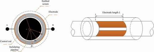
The four-part sensor contains the insulating ceramic tube wall, the metal control rod, the air gap between the tube wall and the control rod, and the stainless electrodes. The electrodes are placed on the insulating tube outside wall, and the control rod can be specified as ungrounded or grounded. R1 is the inner radius of the control rod. R2 and R3 denote the inner and outer radius of the dielectric pipe, respectively. α is the angle between the two electrodes. L is the length of the two surface-plate electrodes. Other parameters are as follows: R1 = 7 mm, R2 = 8 mm, R3 = 11 mm, α = 170°, L = 990 mm.
It is worth noting that the surface of the two-electrode sensor is sealed using insulating materials to prevent direct contact of the capacitance electrodes with the control rod or earthed screen. The central angle of the electrode is 170 degrees. The selected central angle is an optimal result based on the previous research in 2017 [Citation11].
2.2. Electric model
We now propose a general model for getting more into the physical mechanism of the phenomena in order to give a general tool to design capacitance probes when an ungrounded/grounded control rod is used. The system between the two electrodes A and B is modeled by the impedance Z ()), while the electronics is simplified as an ideal amperometer with zero input impedance measuring the current iB. Under the ideal condition, the control rod is ungrounded, and the current iB from node A goes through Z. Current iB is measured by an amperometer placed in B.
Figure 2. Electrical model of the two-electrode capacitance sensor.
However, when the control rod is grounded, there is a coupling between the control rod and the measurement space in NHR with consequent electrical losses. The coupling mechanisms should be direct contact with the metallic parts of the reactor pressure vessel in NHR. These losses are introduced in the electrical model as an additional impedance Zai as shown in ).
Since the control rod is grounded and the symmetry of the two-electrode sensor, the current i is split into the two circuit branches (iB and iai) according to the values of Z/2 and Zai. Therefore, the current that reaches node B is affected by the leakage current iai through Zai. Due to the presence of leakage current iai, the electrical current iB is indicated as EquationEquation (1)(1)
(1) .
where V is a potential difference between A and B.
In the meanwhile, the equivalent impedance ZB between A and B in ) is as shown in EquationEquation (2)(2)
(2) .
The equivalent impedance ZB is generally defined as the total impedance a device or circuit offers to the flow of an alternating current (AC) at a given frequency, and is represented as a complex quantity. The equation for calculating sensor capacitance CB is proposed by making the reciprocal of equivalent impedance equated, and the positive correlation between CB and 1/ZB is given as:
where f(1/ZB) represents a monotone function.
Ideally when the control rod is ungrounded, Zai approaches the infinity so that the current entering node A gets out at node B (ZB = Z) in EquationEquation (2)(2)
(2) . Whereas, it also can be seen from ) that in reality Zai has a finite value when the control rod is grounded. In addition, we can obtain ZB > Z from EquationEquation (2)
(2)
(2) and a decreasing CB from EquationEquation (3)
(3)
(3) obviously with ZB > Z. That is to say, as the control rod is grounded, Zai becomes very small, iai cannot hence be neglected and the expected decreasing tendency of CB is observed.
3. Experiment facility description
3.1. Measurement circuits
The measurement circuits are developed independently. For a capacitance sensor, there are two main considerations: (1) sensor structure (see ) and (2) the sensor interface electronics. There are several commercial measurement methods to choose from when measuring impedance, each of which has advantages and disadvantages [Citation16–Citation19]. The most appropriate method should match the measurement requirements and conditions, while considering such factors as frequency coverage, measurement range, measurement accuracy, and ease of operation. The choice will require us to make tradeoffs as there is not a single measurement method that includes all measurement capabilities.
We can anticipate here that these commercial tools can be used when the control rod is ungrounded or grounded. On the contrary, the challenge we confront here is to measure the capacitance when the control rod is grounded. The auto-balancing bridge method is commonly used in grounded device measurements. Meanwhile, its operational frequency range has been extended up to 110 MHz. This type of instrument has a disadvantage in accuracy at high frequencies because of the performance limits of the amplifier. The auto-balancing bridge instruments for low frequency impedance measurement (below 100 kHz) usually employ a simple current-voltage converter circuit (an operational amplifier with a negative feedback loop) in place of the ammeter as shown in . The bridge section works principle is as follows.
Figure 3. The equivalent circuit of auto-balancing method.
In , the test signal current i flows through the device under test (DUT) and also flows into the current-voltage converter. The operational amplifier of the current-voltage converter makes the same current as i which flow through the resistor Rr on the negative feedback loop. Since the feedback current i is equal to the input current i flows through the Rr and the potential at the lower terminal is automatically driven to zero volts. Thus, it is called virtual ground. The current-voltage converter output voltage V2 is represented by the following equation:
where, i is determined by the impedance ZB of the DUT and the voltage V1 across the DUT as follows:
From EquationEquations (4)(4)
(4) and (Equation5
(5)
(5) ), the equation for impedance ZB of the DUT is derived as
The vector voltages V1 and V2 are measured with the vector voltmeters as shown in . Since the value of Rr is known, the complex impedance ZB of the DUT can be calculated by using EquationEquation (6)(6)
(6) .
The electronic circuits are developed independently to meet our actual measurement requirements as shown in . There are three differences between the in-house circuit and the commercial circuit. Firstly, the in-house circuit has less unrelated features and lower cost. Secondly, the precision of in-house circuit can be much higher under certain conditions with fewer features. This is because the in-house circuit does not need to balance other uncorrelated measurement requirements. Thirdly, other modifications can be made on in-house circuit according to the measurement requirements.
Figure 4. In-house control rod position measurement circuits.

3.2. Measurement system
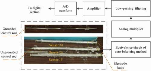
The principle of ungrounded/grounded control rod position measurement using a two-electrode capacitance sensor and corresponding system is shown in . Capacitance sensors with the electrodes flush mounted on the insulating pipe wall have to measure small capacitance variations. The overall capacitance between the electrodes is in the order of 10 pF or 100 pF. To reduce cable stray capacitances, we use an AC-based electronics. The capacitance CB of the DUT is excited applying at the node A (see ) a sinusoidal voltage V = 1V at frequency f = 30 kHz. The corresponding impedance ZB is measured by the equivalent circuit of auto-balancing method (see ). The output voltages V1 and V2 of the equivalent circuit of auto-balancing method are sinusoidal signals, whose amplitudes are determined by the value of the capacitance CB. In , an analog multiplier followed by a low-pass filtering and an amplifier relates the output voltages V1 and V2. Then the signals are processed by the A/D transform converter.
Figure 5. Schematic diagram illustrating the principle of the measurement system.
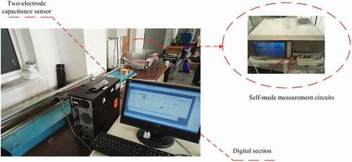
3.3. Experiment and calibration bench
The full-size test bench is shown in the . In reality, the control rod position is not easy to measure directly. We usually measure the position of a metal bar connected to the control rod. The static calibration experiment of two-electrode capacitance sensor was completed on this full-size special designed test bench. Calibration should be done before its field application. The grating probe connected to the computer to calibrate the capacitance control rod position sensor.
Figure 6. Full-size test bench.
4. Results and discussion
Three sets of capacitance sensing devices including sensor 1#, 2#, and 3# were installed for the control rod position measurement (see ). The insertion depth x (control rod position) of the metallic control rod varies from 0 to 800 mm with 100 mm interval. This is to reproduce an insertion process of the control rod into the NHR background material at the specified cross-sectional position. In each set of capacitance sensor, the characteristics of ungrounded and grounded control rod positions were obtained and analyzed.
4.1. Ungrounded control rod position measurement
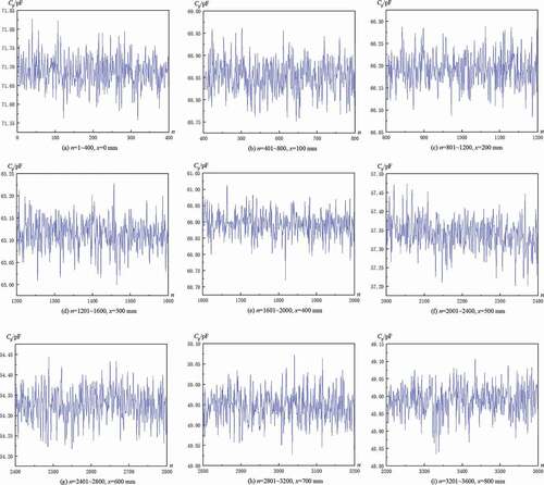
Through test data processing and analysis, the parameters variation trends of various sensors are similar when the control rod is ungrounded. The experimental results of sensor 1# are taken as an example. The metallic control rod position x varies from 0 to 800 mm. Measurement was conducted 400 times a position. Thus, 3600 groups of data were obtained from each sensor when the control rod is ungrounded in .
Figure 7. (a)~(f).Graphs showing the variation of sensor 1# capacitance Cp versus measurement times n at different control rod positions with the ungrounded control rod.
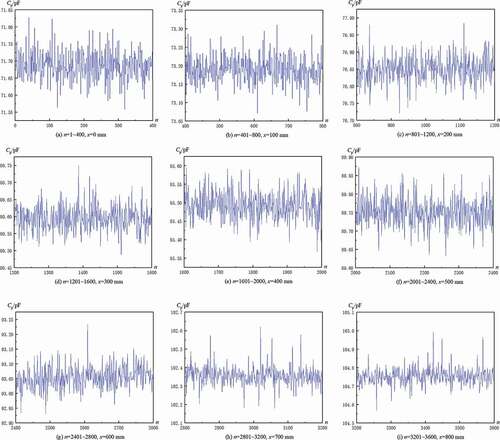
In , it was found that the maximum measurement capacitance Cp of sensor 1# was around 104.75 pF. The capacitance Cp and control rod position x variation curves with the detected ungrounded control rod acquired by the 1# measurement sensor over the 3600 times are shown in .
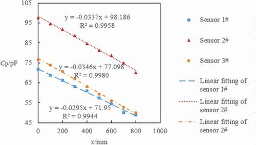
Figure 8. Capacitance variations curve with ungrounded control rod positions of three sensors.
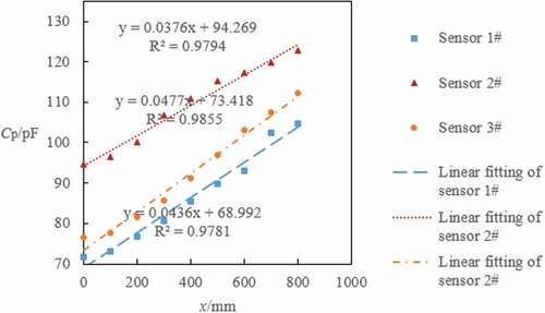
By preliminarily analyzing the 3600 groups of data acquired, the measured capacitance of the 9 control rod positons are 71.6872 ± 0.0039 pF, 73.1898 ± 0.0034 pF, 76.8500 ± 0.0037 pF, 80.5951 ± 0.0035 pF, 85.4923 ± 0.0036 pF, 89.7512 ± 0.0036 pF, 93.0544 ± 0.0036 pF, 102.3561 ± 0.0048 pF, 104.7546 ± 0.0045 pF, respectively, with 95% confidence interval. In addition, 800 mm variation of the control rod position can lead to 33.0700 pF changes of the capacitance. The average sensor capacitance sensitivity is 0.0436 pF/mm. Therefore, the measurement accuracy of the nine control rod positons are ± 0.09 mm, ± 0.08 mm, ± 0.08 mm, ± 0.08 mm, ± 0.08 mm, ± 0.08 mm, ± 0.08 mm, ± 0.11 mm, ± 0.10 mm, respectively, with 95% confidence interval. From the above analyses, the measurement accuracy of sensor 1# is as high as 0.11 mm.
In , the capacitance variations of sensor 1# at nine insertion depths are basically consistent. The capacitance data detected at the nine control rod positions from 0–800 mm increases monotonously. It is worth mentioning that Zai approaches the infinity when the control rod is ungrounded. According to EquationEquations (2)(2)
(2) and (Equation3
(3)
(3) ), ZB equals Z. As metal resistance is smaller than air, the impedance ZB decreases with the increase of the control rod inserting depth. The capacitance values of different sensor parts are connected in parallel. Along with the increase of the insertion depth, the capacitance increases too. The similar tendencies between the capacitance data and the control rod positon of sensor 2# and 3# can be obtained which are shown in . And the measurement accuracy of sensor 2# and 3# are also as high as 0.05 and 0.60 mm, respectively. The difference of measurement accuracy among the above three sensors is mainly due to the difference of dielectric constant of the insulating tube walls and the eccentric rod motion process (see ).
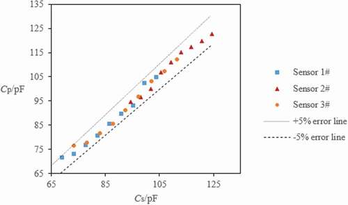
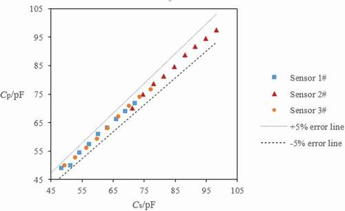
shows the error curve of calculated value Cs and experimental value Cp when the control rod was ungrounded. Cs is calculated according to the linear fitting formula (see ). The calculated value and experimental value error are within 5% for three sensors. From , errors caused by eccentricity or other factors are within the reasonable range.
Figure 9. Error curve of the calculated value Cs and experimental value Cp when the control rod was ungrounded.
4.2. Grounded control rod position measurement
In , the variation of sensor 1# capacitance versus measurement times n at different control rod positons with the grounded is given. The experimental result of sensor 1# is also taken as an example. The range of values for the metallic control rod position x is 0–800 mm. It is measured 400 times per position. Hence, the capacitance data were measured in totally 3600 groups from each sensor when the control rod is grounded in .
Figure 10. (a)~(f).Graphs showing the variation of sensor 1# capacitance Cp versus measurement times n at different control rod positions with the grounded control rod.
From , the maximum measurement capacitance Cp in sensor 1# was around 71.69 pF. According to data analysis, the measurement capacitance of the nine control rod positons are 71.6872 ± 0.0039 pF, 68.8536 ± 0.0037 pF, 66.1907 ± 0.0035 pF, 63.1156 ± 0.0034 pF, 60.8918 ± 0.0037 pF, 57.3397 ± 0.0041 pF, 54.327 ± 0.0039 pF, 49.946 ± 0.0037 pF, 48.9877 ± 0.0041 pF, respectively, with 95% confidence interval. Besides, 800 mm variation of the control rod position can lead to 22.6995 pF changes of the capacitance.
The average sensor sensitivity is −0.029 pF/mm. Therefore, the measurement accuracy of the nine control rod positons are ± 0.13 mm, ± 0.13 mm, ± 0.12 mm, ± 0.12 mm, ± 0.13 mm, ± 0.14 mm, ± 0.13 mm, ± 0.13 mm, ± 0.14 mm, respectively, with also 95% confidence interval in . The device measurement accuracy is as high as 0.14 mm.
Figure 11. Capacitance variations curve with grounded control rod positions of three sensors.
In , the capacitance data measured at nine control rod positions from 0–800 mm decreases monotonously. In particular, Zai is obvious decreased when the grounded control rod is inserting. From EquationEquations (2)(2)
(2) and (Equation3
(3)
(3) ), ZB can be greater than Z. As the grounded capacitance is introduced (see )), the impedance ZB increases with the increase of the control rod position. The capacitance values of different sensor parts are also connected in parallel. Thus, the capacitance decreases too. In sensor 2# and 3#, the results are similar to those in sensor 1# as shown in . At the same time, the measurement accuracy of sensor 2# and 3# are also as high as 0.05 and 0.60 mm, respectively. The measurement accuracy of three sensors differs because of the dielectric constant difference and the eccentric rod motion process (see ).
shows the error curve of calculated value Cs and experimental value Cp when the control rod was grounded. The calculated value and experimental value error are also within 5% for three sensors. Errors caused by eccentricity or other factors are in the reasonable range from .
Figure 12. Error curve of the calculated value Cs and experimental value Cp when the control rod was grounded.
4.3. Measurement experiences
There are several things to notice above. Connecting a DUT to the measurement terminals of the auto-balancing bridge instrument requires a test fixture or test cables. The selection of the appropriate test fixtures and cables, as well as the techniques for obtaining the optimum DUT connection configuration, are important for maximizing the total measurement accuracy. The four-terminal configuration can reduce the effects of lead impedances and contact resistances because the signal current path and the voltage sensing leads are independent. Typical factors for measurement discrepancies in impedance measurements are listed as follows: variance in residual parameter value; a difference in contact condition; a difference in open/short compensation conditions; electromagnetic coupling with a conductor near the DUT; and variance in environmental temperature. Stray capacitance between the contact electrodes of a test fixture is a significant error factor compared to the residual impedance. To make interconnections with the DUT, use a shielded four-terminal configuration. Proper guarding techniques and the open/short compensation can minimize the effects of stray capacitance.
5. Conclusions
This study proposes a new apparatus for measuring control rod position that uses capacitance parameter. In addition, the proposed model was set up with ungrounded/grounded control rod for the two-electrode sensor. According to the different electric properties of ungrounded and grounded control rod, this apparatus determines the control rod position using an interface electronics method and two-electrode capacitance sensor. Moreover, the accuracy and error of two-electrode capacitance sensors based on the experiment and calibration data are desirable.
A control rod position sensor based on two-electrode capacitance has achieved preliminary success in a laboratory study and experiment. At the same time, there is still a room for improvement. For example, the metal measuring rod is interfered by external electromagnetic field and required high requirement of ground or ungrounded condition which lead to the low measuring resolution. After the aforementioned problems are solved, the system will be considerably improved. Using the system, it is feasible to measure the control rod positon in NHR. The control rod position data thus obtained can subsequently provide reliable data for research on the further development of the device.
Acknowledgments
The authors would also like to thank Mr Fulong Zhao for the assistance and discussion during the test bench construction.
Disclosure statement
No potential conflict of interest was reported by the authors.
References
- Dazhong W, inventor; Tsinghua university patent office, assignee. Reactor control rod ultrasonic rod position measurement system. China patent CN 1044184. 1990 Jul 05
- Maurio Joseph M, McCarthy C, Lawson Marie A. Fluxgate magnetometer based control rod position indication for Small Modular Reactors. 9th International Topical Meeting on Nuclear Plant Instrumentation, Control, and Human-Machine Interface Technologies, NPIC and HMIT, 2015 Feb 22–26; Charolett, NC; p. 162–172
- Wenran W, Dezhong L, Nianzu Y, et al. Inductance transducer coded by coils and armatures for control rod position. J Tsinghua Univ: Nat Sci Ed. 1996;36:45–50, [in Chinese].
- Hsueh HT, Lin CT. An incremental double-layer capacitance of a planar nano gap and its application in cardiac-troponin T detection. Biosens Bioelectron. 2016;79:636–643.
- Shin DM, Shin YC, Lee JH, et al. Highly sensitive detection of epidermal growth factor receptor expression levels using a capacitance sensor. Sensor Actuat B-Chem. 2015;209:438–443.
- Lee SM, Han N, Lee R, et al. Real-time monitoring of 3D cell culture using a 3D capacitance biosensor. Biosens Bioelectron. 2016;77:56–61.
- Kerpel KD, Keulenaer TD, Schampheleire SD, et al. Capacitance sensor measurements of upward and downward two-phase flow in vertical return bends. Int J Multiphase Flow. 2014;64:1–10.
- Assima GP, Larachi F, Schleicher E, et al. Capacitance wire mesh imaging of bubbly flows for offshore treatment applications. Flow Meas Instrum. 2015;45:298–307.
- Salazar AO, Dunford W, Stephan R, et al. A magnetic bearing system using capacitive sensors for position measurement. IEEE T Magn. 1990;26:541–2543.
- Guang H, Hanliang B. Design of two-electrode capacitance sensor for control rod position measurement. Atomic Energy Sci Technol. 2017;51: 2352–2356. [in Chinese].
- Yang W. Design of electrical capacitance tomography sensors. Meas Sci Technol. 2010;21:447–453.
- Lin TT, Du Y, Mao J. Monitoring of icing behavior based on signals from a capacitance sensor. Optik. 2016;127:4650–4655.
- Pengmin Pan TP, McDonald BK. Via. Predicting moisture content of chipped pine samples with a multi-electrode capacitance sensor. Biosyst Eng. 2016;145:1–9.
- Kerpel KD, Keulenaer TD, Schampheleire SD, et al. Capacitance sensor measurements of upward and downward two-phase flow in vertical return bends. Int J Multiphase Flow. 2014;64:1–10.
- Hu B, Wang J, Song G, et al. A compact wideband precision impedance measurement system based on digital auto-balancing bridge. Meas Sci Technol. 2016;27:055902.
- Liu G, Dong Z, Li D, et al. Impedance measurement of quartz crystal based on network analysis method. Proc SPIE Int Soc Opt Eng. 2011:7997(2):92.
- Walker B, inventor; Nautel Limited, assignee. Impedance measurement in an active radio frequency transmitter. United States patent US 8213885. 2012 Jul 03.
- Pan Q, Xiao D, Deng M, et al. A voltage-current method of measuring ultrasonic transducer impedance. IEEEFENDT-2013.2013 Jun 17–20;125–128.
- Ferguson JG. Classification of bridge methods of measuring impedances. Electr Eng. 2013;52:414.