
 ?Mathematical formulae have been encoded as MathML and are displayed in this HTML version using MathJax in order to improve their display. Uncheck the box to turn MathJax off. This feature requires Javascript. Click on a formula to zoom.
ABSTRACT
Seismic design of nuclear power plants (NPPs) is important for ensuring their integrity during earthquakes. Seismic analysis has been conducted using lumped mass beam models (LMBMs) for the design of plants in Japan, whereas three-dimensional (3D) finite element models (FEMs) have been used for novel plants outside Japan. The purposes of this study are to organize issues related to the development and application of 3D FEMs for seismic analysis of Japanese NPPs and to indicate future study directions. To organize these issues, the authors systematically investigated: (1) international guides and standards related to seismic analysis and (2) 3D FEMs of novel NPPs outside Japan. By considering other studies on the issues, the authors suggest directions for future studies. Resolving the issues will contribute to application of 3D FEMs for seismic analysis in the design of Japanese NPPs.
1. Introduction
Seismic design of nuclear power plants (NPPs) is important for ensuring their integrity during earthquakes. For such design, seismic analysis of major structures in NPPs such as reactor buildings has generally been conducted using analysis models that consider soil–structure interaction (SSI). The results have been used to develop seismic design conditions (e.g. acceleration response spectra and sectional forces) for structures, systems, and components (SSCs). The study reported in this paper focused on SSI analysis models to develop the seismic design conditions.
Seismic analysis of major structures in Japanese NPPs has mainly used lumped mass beam models (LMBMs) as SSI analysis models, though some applicants (e.g. [Citation1]) undergoing licensing examination by Japan’s Nuclear Regulation Authority (NRA) have used three-dimensional (3D) finite element models (FEMs) to validate their LMBMs, in accordance with NRA guidelines [Citation2,Citation3]. In contrast, 3D FEMs have mainly been used as SSI analysis models of major structures in NPPs outside Japan. For example, the seismic analysis in developing an advanced passive plant, the AP1000, was conducted using a 3D FEM [Citation4]. NUREG-0800 [Citation5] and ASCE/SEI 4-16 [Citation6], which are representative guides and standards for seismic design of NPPs outside Japan, generally expect the use of 3D FEMs. This constitutes a major difference in the types of SSI analysis models used for NPPs in Japan and the other countries.
As mentioned by Yoshimura et al. [Citation7], 3D FEMs have certain advantages, such as helping explain the 3D dynamic behavior of structures during earthquakes to third parties. Hossain [Citation8] indicated the advantages of 3D FEMs by comparing their characteristics with those of LMBMs. Tabatabaie et al. [Citation9] also revealed the characteristics and advantages of 3D FEMs by comparing seismic analysis results obtained from a 3D FEM of a U.S. European pressurized water reactor (U.S. EPR) plant with those obtained from an LMBM of that plant. Accordingly, it would be useful to apply 3D FEMs as SSI analysis models for NPPs in Japan. To enable the application of 3D FEMs, it is essential to systematically organize issues related to the development and application of 3D FEMs.
Therefore, the purposes of this paper are to organize the issues and suggest directions for future studies in applying 3D FEMs for seismic analysis of NPPs in Japan instead of LMBMs. As a preliminary, we briefly outline the characteristics and advantages of 3D FEMs on the basis of studies on seismic analysis using 3D FEMs. Then, we organize the related issues on the basis of our investigations into: (1) international guides and standards related to seismic analysis, and (2) modeling methods used in developing 3D FEMs of novel NPPs outside Japan. Finally, we consider other studies on these issues and suggest directions for future studies.
2. Overview of major structures in NPPs and analysis models
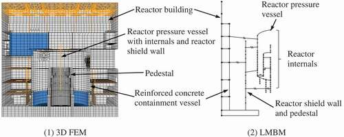
In this section, we outline major structures in NPPs and their analysis models. To demonstrate examples of major structures, shows a schematic of a reactor building in an advanced boiling water reactor (ABWR) plant. As illustrated in the figure, the major structures house SSCs, such as the reactor pressure vessel and reactor shield wall, and also large amounts of fluid in certain structures, such as the spent fuel pool. Additionally, the major structures are surrounded by soil. Major structures that are considered in conjunction with their foundations and supporting media in seismic analysis are defined as primary structures [Citation10] (seismic systems [Citation5]). SSCs supported by the primary structures are defined as substructures [Citation10] (seismic subsystems [Citation5]).
Figure 1. Schematic of ABWR reactor building.
shows examples of a 3D FEM and an LMBM serving as SSI analysis models for the reactor building in . As illustrated in 1), a 3D FEM includes various types of finite elements, such as shell and solid elements. They can be used to obtain the seismic responses (i.e. acceleration, sectional forces, stresses, and strains) of individual structural members. In contrast, as illustrated in 2), LMBMs consist mainly of beam, lumped mass, and spring elements. Each finite element represents some structural members together, e.g. one beam element represents some seismic walls, and is generally used to obtain the seismic responses of some structural members.
Figure 2. Examples of SSI analysis models.
3. Characteristics and advantages of 3D FEMs
We retrieved articles related to seismic analysis of NPPs by using 3D FEMs. The keywords included ‘nuclear power plant’ (e.g. ‘US advanced pressurized water reactor (US-APWR)’ and ‘advanced power reactor (APR) 1400’), seismic analysis, 3D FEM, three-dimensional finite element method, and combinations of these keywords. From the articles retrieved, we identified certain articles discussing the characteristics and advantages of 3D FEMs. By investigating these articles [Citation7–Citation9,Citation11–Citation16], we found three major characteristics of 3D FEMs, as described below with key advantages.
The first major characteristic is the capability of directly evaluating the seismic responses of each structural member. This characteristic has the key advantage of enabling direct consideration of local (and global) structural upgrades to increase seismic integrity. The effectiveness of such upgrades can be evaluated, for example, by modifying certain structures of an original 3D FEM (without upgrades) and examining the resulting decreases in seismic responses. Choi et al. [Citation11] conducted a seismic analysis of a reactor vessel by using a 3D FEM and obtained decreases in seismic stresses by changing the vessel’s support locations. Additionally, to decrease seismic stresses, Zhao et al. [Citation12] optimized the locations and shapes of the air intakes of a shield building in an AP1000 plant on the basis of a sensitivity analysis using a 3D FEM of the building.
The second major characteristic is the capability of modeling individual structural members. This characteristic has the following two advantages. The first is that 3D FEMs can easily simulate local vibration phenomena, such as torsional vibration and out-of-plane vibration of individual walls and floors inside structures [Citation9,Citation13–Citation16]. In contrast, it is difficult to precisely evaluate such vibration phenomena with LMBMs because of those models’ simplification. The second advantage is that 3D FEMs for seismic analysis is also available for other structural analyses (e.g. flow-induced vibration analysis and thermal stress analysis), as mentioned by Choi et al. [Citation11]. This means that both seismic stresses/strains and stresses/strains obtained from other analyses can easily be combined, because the 3D FEMs used for both analyses have the same elements. Therefore, uncertainty related to the combination (i.e. uncertainty from using separate analysis models for each analysis) can be eliminated.
The third major characteristic is that the spatial distribution of mass, stiffness (including nonlinearity), damping, and input motion can be included in a 3D FEM, as described by Yoshimura et al. [Citation7] and Tabatabaie et al. [Citation9]. Inclusion of these elements can lead to increased accuracy of seismic analysis results, though seismic analysis with a 3D FEM takes more calculation time than analysis with an LMBM because of the larger numbers of elements.
As described above, 3D FEMs have many advantages; thus, it should be useful to apply them as SSI analysis models for NPPs in Japan. 3D FEMs require more calculation time, however, than do LMBMs. For the actual design of NPPs, seismic analyses must be conducted under many kinds of conditions, such as input motion variation, soil stiffness variation, and so forth. Therefore, 3D FEMs requiring less calculation time (i.e. practical 3D FEMs) would be desirable.
4. Issues related to development and application of 3D FEMs
To review and organize issues related to the development and application of 3D FEMs for seismic analysis of NPPs in Japan, we investigated articles related to the seismic analysis. To develop a systematic review strategy, we consider a primary structure modeled as a multi-degree-of-freedom system subjected to an input force. The equation of motion for the system is given by:
where M is the mass matrix, C is the damping matrix, K is the stiffness matrix, y is the relative displacement vector, and P(t) is the external force vector (or the input motions to the system).
Obtaining analysis results for the system thus entails constructing and solving EquationEquation (1)(1)
(1) . The mass and stiffness matrices can be automatically constructed by developing the structural parts of a 3D FEM of the structure, though the masses of internal SSCs that are not explicitly modeled in the 3D FEM must also be included. Fluids contained in the structure must also be modeled. Additionally, the damping matrix has to be constructed using a damping model such as Rayleigh damping. Moreover, accurate application of the external force requires modeling the SSI. Accordingly, we decided to investigate articles in terms of structural modeling, fluid modeling, damping modeling, and SSI modeling. In addition to these viewpoints, we also investigated verification and validation (V&V) of SSI analysis models, which is important to ensuring the reliability of such analyses.
In the following sections, we apply the above viewpoints as an organizational framework. Specifically, we outline international practices (i.e. outside Japan) in NPP development, including requirements for representative international guides and standards for seismic analysis [Citation5,Citation6,Citation10,Citation17] and modeling methods for the 3D FEMs of the AP1000 [Citation4], US EPR [Citation18], US-APWR [Citation19,Citation20], and APR1400 [Citation21,Citation22], which are novel NPPs outside Japan. Additionally, we retrieved articles related to 3D FEM seismic analysis of NPPs by using keywords: structural modeling, fluid modeling, damping modeling, SSI modeling, and V&V. From the articles retrieved here and those retrieved in Section 3, we identified certain studies that develop modeling methods from each viewpoint and verify them by comparing other methods, experiments, and so forth. We review those studies mainly and suggest directions for future studies.
4.1. Structural modeling
4.1.1. Outline of international practices
As described in Section 2, SSCs are categorized into primary structures and substructures. First, we briefly outline the requirements of international guides and standards for modeling primary structures. In NS-G-1.6 [Citation17], the International Atomic Energy Agency (IAEA) requires that the details of analysis models for primary structures be consistent with the analysis objectives, and that the models be able to represent local vibration modes corresponding to the objectives. According to NUREG-0800 [Citation5], we can use both LMBMs and 3D FEMs to model primary structures if these models satisfy NUREG-0800 requirements, such as the capability of evaluating local vibration modes (e.g. individual floor vibration modes). It is difficult to precisely evaluate such modes with LMBMs because of those models’ simplification; thus, this requirement implies the use of 3D FEMs. ASCE/SEI 4-16 [Citation6] basically requires that 3D FEMs be used, though LMBMs can also be used when the document’s requirements are met. The European Utility Requirements (EUR) document [Citation10] specifies that analysis models for primary structures be 3D and made of finite elements. Accordingly, we conclude that these guides and standards basically expect the use of 3D FEMs as analysis models for primary structures, though LMBMs are not prohibited from use.
Next, we outline the requirements of international guides and standards for modeling substructures. All the guides and standards give criteria for selecting the substructures analyzed with the primary structures. According to NUREG-0800, SSCs housed in primary structures are analyzed as decoupled systems in most cases, though one important exception is reactor coolant systems, which are usually analyzed together with the primary structures. NS-G-1.6 requires that suitable analysis models for coupled substructures, providing at least the same frequencies and modal masses as detailed analysis models for the coupled substructures, should be included in analysis models for primary structures. ASCE/SEI 4-16 states that detailed analysis models for coupled substructures are not required for evaluating the global responses of primary structures if simpler analysis models can represent major effects. NS-G-1.6 and ASCE/SEI 4-16 allow the use of simple analysis models for coupled substructures. Therefore, we conclude that properly simplified analysis models for substructures can be coupled with analysis models for primary structures.
Next, we consider the SSI analysis models used for the aforementioned novel NPPs. and [Citation13] illustrates an example of an SSI analysis model for the AP1000. This model consists of 3D FEMs of primary structures such as a shield building (a cylindrical tower structure shown in ) together with LMBMs of substructures such as a reactor coolant system (). Note that such substructures have typically been modeled with LMBMs [Citation4,Citation18–Citation22]. This 3D FEM includes the masses of decoupled SSCs. This modeling methodology accords with the aforementioned international guides and standards and is common for other novel NPPs.
Figure 3. 3D FEM of primary structures for AP1000.
Reprinted from Nuclear Engineering and Design, 237, Tuñón-Sanjur L. et al., Finite element modeling of the AP1000 nuclear island for seismic analyses at generic soil and rock sites, 1474–1485, Copyright (2007), with permission from Elsevier.
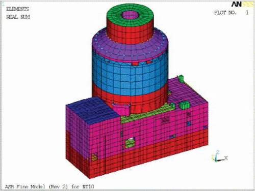
Figure 4. LMBM of substructures for AP1000.
Reprinted from Nuclear Engineering and Design, 237, Tuñón-Sanjur L. et al., Finite element modeling of the AP1000 nuclear island for seismic analyses at generic soil and rock sites, 1474–1485, Copyright (2007), with permission from Elsevier.
Finally, we compare the types of SSI analysis models used for Japanese NPPs with those used for the novel plants. The former have consisted of LMBMs for both primary structures and substructures (e.g. [Citation1]), though LMBMs consisting only of primary structures have also been used. In contrast, primary structures for the novel plants have been modeled with 3D FEMs, while their substructures have been modeled with LMBMs. This comparison indicates that we first need to develop 3D FEMs of primary structures in Japanese NPPs. After that, we should develop 3D FEMs of substructures in order to simultaneously conduct detailed seismic analysis of both primary structures and substructures.
4.1.2. Studies on structural modeling of primary structures
As described in Section 4.1.1, we first need to develop 3D FEMs of primary structures, so we investigated studies on this development. For NPPs outside Japan, Pinto et al. [Citation23] developed a 3D FEM of a reactor building and examined their FEM by comparing results obtained from simulation analysis of a recorded earthquake with actual results. Nour et al. [Citation24] developed a 3D FEM of a pressurized heavy water reactor power plant for seismic analysis and calibrated the FEM using ambient vibration test results of that plant.
For NPPs in Japan, Rangelow et al. [Citation25] and Moore et al. [Citation26] developed 3D FEMs of the reactor building of Kashiwazaki-Kariwa NPP (KK) unit No. 7 and conduct simulation analyses of a recorded earthquake to validated their FEMs. Hijikata et al. [Citation27] developed a 3D FEM of the reactor building of KK unit No. 5 and confirmed the validity of their FEM by comparing results obtained from the FEM with recorded earthquakes. Kasuga et al. [Citation28] also verified a 3D FEM of a pressurized water reactor plant by comparing recorded earthquakes with simulation analysis results obtained from their FEM.
These studies demonstrate that 3D FEMs providing analysis results corresponding to observed results can be developed for primary structures in Japanese NPPs. None of the above studies, however, includes the material nonlinearity of the reinforced concrete (RC) constituting primary structures. Design-basis earthquakes for NPPs in Japan are large, and RC exhibits nonlinear dynamic behavior. We therefore investigate studies on modeling methods for RC material nonlinearity in 3D FEMs.
We briefly introduce studies on developing methods for dealing with such nonlinearity and validating analysis results by comparison with tests conducted by the Nuclear Power Engineering Corporation (NUPEC) and Japan Nuclear Energy Safety Organization (JNES). Ueda et al. [Citation29] validated their modeling method for RC material nonlinearity through comparison of vibration tests using RC seismic shear walls conducted by the NUPEC (called seismic ultimate dynamic response test) and simulation analysis results. Hasegawa et al. [Citation30], Inoue et al. [Citation31], Hibino et al. [Citation32], and Nakamura et al. [Citation33] also conducted simulation analyses of the same tests and found agreement between the respective results. Naganuma et al. [Citation34,Citation35] conducted simulation analyses of the vibration tests and other tests using RC (and prestressed concrete) specimens, and they concluded that the analyses agreed with the test.
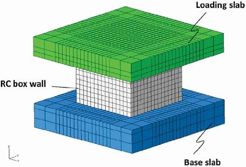
As another approach for examining nonlinear material modeling for RC, Ono et al. [Citation36] conducted simulation analyses of two-directional static loading tests using both cylindrical and box-type RC walls conducted by the NUPEC and JNES. The NUPEC and JNES also conducted vibration tests with the same specimens, and Yabuuchi et al. [Citation37] and Torita et al. [Citation38] examined their nonlinear material modeling method for RC by comparing simulation analysis results with those test results. Recently, Syed and Gupta [Citation39] conducted simulation analysis () of the same vibration test and obtained similar results to the test results.
Figure 5. 3D FEM of multi-axis loading tests on RC shear walls.
Reprinted from Nuclear Engineering and Design, 295, Syed S. and Gupta A., Seismic fragility of RC shear walls in nuclear power plant part 2: Influence of uncertainty in material parameters on fragility of concrete shear walls, 587–596, Copyright (2015), with permission from Elsevier.
As described above, many researchers have developed and validated modeling methods for RC material nonlinearity in 3D FEMs. Large international projects related to this topic were surveyed by Richard et al. [Citation40,Citation41]. They also outlined their project called SMART. Zinn et al. [Citation42,Citation43] verified their nonlinear modeling method by comparing test results obtained in the SMART project with their simulation analysis results. To the best of our knowledge, however, only one study has validated modeling methods for RC material nonlinearity on the basis of recorded earthquakes and actual primary structures. Specifically, Kumagai et al. [Citation44] validated their nonlinear 3D FEM of the control building of Onagawa NPP unit No. 2 by conducting a simulation analysis of a recorded earthquake. Continued observation of the earthquake responses of NPP is necessary not only for evaluating plant integrity after earthquakes but also for validating 3D FEMs involving RC material nonlinearity.
4.1.3. Studies on structural modeling of substructures
Properly simplified analysis models for substructures can be coupled with analysis models for primary structures, and the substructure LMBMs used for seismic analysis of NPPs in Japan have been validated through comparison of vibration tests and simulation analyses (e.g. [Citation45]). However, 3D FEMs of substructures can contribute to more precise understanding of their 3D dynamic behavior during earthquakes. We therefore investigate studies on developing 3D FEMs of substructures. In particular, we focus here on reactor coolant systems composed of reactor pressure vessels (or reactor vessels) with their internal structures and coolant water, because reactor coolant systems are often analyzed together with primary structures, as noted in Section 4.1.1.
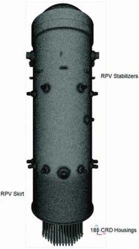
Few studies have developed 3D FEMs of substructures in Japanese NPPs. Yoshimura et al. [Citation7] developed a 3D FEM of a reactor pressure vessel and its internals for seismic analysis (), though this 3D FEM does not include fluid–structure interaction (FSI). To simulate FSI during earthquakes, Yoshimura et al. [Citation46] developed a suitable analysis method and applied it to a 3D FEM of fuel assemblies with reactor coolant water in a boiling water reactor. They conducted a simulation analysis of a vibration test to validate the 3D FEM.
Figure 6. 3D FEM of reactor pressure vessel.
There have also been studies on 3D FEMs of substructures in NPPs outside Japan. Park et al. [Citation47] identified the dynamic characteristics of the APR1400 reactor vessel and its internals by applying modal tests with one-tenth-scale models, and they developed 3D FEMs accordingly. Choi et al. [Citation48] likewise identified the dynamic characteristics of core internal structures inside the reactor vessel of a reactor by applying modal tests with one-twelfth-scale models, and they also developed 3D FEMs. Tong et al. [Citation49] developed both a 3D FEM and LMBM of the main structures of the AP1000 reactor coolant system and conducted seismic analyses using both models. Perov et al. [Citation50] developed a 3D FEM of a reactor vessel and its internals and conducted eigenvalue analyses using the 3D FEM and a LMBM of those structures.
These studies indicate that 3D FEMs of substructures can be developed using state-of-the-art technologies. Fewer studies, however, have conducted seismic analysis using 3D FEMs composed of both primary structures and substructures. Indeed, to the best of our knowledge, there is only one such study: Yamada and Yoshimura [Citation51] conducted a seismic analysis using a 3D FEM of a reactor building together with its substructures. For the input motions to the 3D FEM, they used acceleration time histories obtained from a seismic analysis of the building and large soil volumes using the simulation techniques of Hori et al. [Citation52]. This kind of analysis requires long calculation time and would be difficult to conduct for the actual design of NPPs, because many seismic analyses have to be conducted under various kinds of conditions. We therefore conclude that future studies should focus on developing efficient analysis methods that will enable seismic analysis using 3D FEMs composed of both primary structures and substructures within a practical amount of time for the actual design.
4.2. Fluid modeling
4.2.1. Outline of international practices
First, we outline the fluid modeling requirements of international guides and standards. In NS-G-1.6 [Citation17], the IAEA requires inclusion of the effects of sloshing (convective) and impulsive loads in analysis models of primary structures, but it allows use of simplified fluid models composed of equivalent masses and springs. NUREG-0800 [Citation5] likewise requires inclusion of convective and impulsive effects of fluids in analysis models. On the other hand, it does not require sophisticated FSI analyses using finite elements for seismic loading. ASCE/SEI 4-16 [Citation6] requires inclusion of impulsive effects modeled by mass and convective effects modeled by mass and spring systems in analysis models. The EUR document [Citation10] gives the same requirements as ASCE/SEI 4-16.
Next, we outline the fluid modeling methods used for 3D FEMs of the novel plants. For the APR1400 [Citation22], fluids in pools housed within the primary structures were modeled using simplified fluid modeling methods (fixed-mass and convective systems) based on other studies (e.g. [Citation53]). The engineers of other plants, however, used different modeling methods.
For the US-APWR [Citation19], fluids in pools and pits were modeled as masses because the sloshing effects were considered negligible. For both the AP1000 [Citation4] and the US EPR [Citation18], the modeling methods for fluids contained in primary structures depended on the fluids’ dynamic effects. Fluids in some tanks and pools of these plants were modeled as masses. In particular, the masses were reduced to exclude the sloshing portions and added to the 3D FEMs of the AP1000 and US EPR, because the fluids’ sloshing frequencies are very lower than their primary structures’ natural frequencies, and thus, the fluids do not affect the structures’ seismic responses. Fluids in other tanks and pools of these plants were modeled as masses, and the total mass of each fluid was included in the 3D FEMs. These methodologies do not include the dynamic effects of fluids (convective effects); instead, the dynamic effects on structures were evaluated by static stress analyses using dynamic pressures obtained from TID-7024 [Citation54] and ASCE 4-98 [Citation55].
To the best of our knowledge, sophisticated FSI analysis methods, such as the arbitrary Lagrangian-Eulerian (ALE) method (e.g. [Citation56,Citation57]) or a smoothed particle method with an FEM (e.g. [Citation58]), have not been used in seismic design of the novel plants. Although these methods enable evaluation of both structural dynamic behavior and fluid motion in detail, they require long calculation time, as pointed out by Rydell et al. [Citation59]. Because seismic analysis for actual design has many analysis cases, efficient analysis methods are preferable, and simplified fluid modeling methods are useful when these methods are appropriate. Accordingly, we conclude that we first need to develop simplified fluid modeling methods applicable in 3D FEMs. Then, we can focus on applying sophisticated FSI analysis methods for more detailed seismic analysis.
4.2.2. Studies on fluid modeling
We first outline studies on simplified fluid modeling methods for the 3D FEMs of primary structures other than the above novel plants. To the best of our knowledge, few studies have focused on such development. Onitsuka et al. [Citation60] studied a simplified modeling method for the fluid contained in the suppression pool (). They evaluated the effects of the fluid on the seismic responses of certain structures and found that the fluid could be basically modeled as mass. They obtained the same finding for the fluid contained in the spent fuel pool () [Citation61]. As with these studies, future studies should focus on developing simplified fluid modeling methods for the 3D FEMs of primary structures in Japanese NPPs.
Next, we outline studies on conducting seismic analysis using sophisticated FSI analysis methods. Zhao et al. [Citation56,Citation57] applied the ALE method in seismic analyses considering the FSI of the AP1000 shield building. For another seismic analysis, Xu et al. [Citation58] applied a smoothed particle method to model the fluid in the passive containment cooling system tank of the AP1000 shield building and coupled this fluid model with a 3D FEM of the shield building. From these studies, we conclude that seismic analysis based on sophisticated FSI analysis methods can be conducted, though none of the above studies focused on calculation time. Future studies should also focus on the calculation time required for seismic analysis using these sophisticated analysis methods and develop efficient methods.
4.3. Damping modeling
4.3.1. Outline of international practices
As described in Section 4.1.1, SSI analysis models consist of primary structures together with certain substructures. The substructures often have different damping ratios from the primary structures, and in NS-G-1.6 [Citation17], the IAEA states that particular care should be given to modeling of the damping of substructures. The other guides and standards [Citation5,Citation6,Citation10] allow various damping modeling methods, depending on the types of analysis methods. Here, we briefly describe the representative damping modeling methods: hysteretic damping (complex stiffness), composite modal damping, and Rayleigh damping.
Hysteretic damping is used in seismic analysis methods based on the complex frequency response. In this approach, damping is modeled by the imaginary parts of a complex stiffness matrix. These imaginary parts are developed for each structure in an SSI analysis model and then combined to form integrated damping matrices. The damping ratios of each structure are used to determine the coefficients of the imaginary parts. The engineers of all the novel NPPs discussed in this paper [Citation4,Citation18–Citation22] conducted seismic analysis based on the complex frequency response and used hysteretic damping.
Composite modal damping is used in seismic analysis methods based on the modal time history response, where damping is modeled by the damping ratios of each natural mode. Since the damping ratios of both primary structures and substructures are different, these methods require composite modal damping ratios. Approaches for obtaining these ratios include stiffness-weighted and mass-weighted modal damping [Citation5,Citation6,Citation10]. For the AP1000 [Citation4], stiffness-weighted modal damping was used to conduct seismic analysis under hard-rock site conditions.
In addition to the above modeling methods, Rayleigh damping was used in conducting seismic analysis of the APR1400 [Citation21] by a direct time-integration method. Rayleigh damping entails a damping matrix composed of a linear combination of mass and stiffness matrices. The purpose of this analysis was V&V for a 3D FEM of the APR1400.
As for the damping modeling methods used for NPPs in Japan, seismic analysis has been conducted using a nonlinear time history response method to simulate the nonlinear behavior of the RC constituting primary structures, and an equivalent damping matrix (Wilson-Penzien damping) [Citation62,Citation63] has been used in these analyses [Citation64]. Construction of the equivalent damping matrix requires modal damping ratios, which have often been calculated by stiffness-weighted modal damping (also called strain energy proportional damping).
From the comparison between damping modeling methods used for Japanese plants and those for plants outside Japan, we find that seismic analysis of NPPs in Japan has involved the same method (stiffness-weighted modal damping) used in international practices to obtain modal damping ratios. We can apply the same method to obtain modal damping ratios for seismic analysis of Japanese plants using 3D FEMs. As some studies (e.g. [Citation65]) have pointed out, however, the equivalent damping matrix is a full matrix, making it difficult to efficiently solve the equation of motion when applying this method with 3D FEMs. We therefore investigate studies on both development of other damping matrices and efficient solution methods for an equation of motion constructed with an equivalent damping matrix.
4.3.2. Studies on damping modeling
We first investigate previous studies on developing damping matrices using methods other than the equivalent damping matrix. These studies have used matrices based on Rayleigh damping, element Rayleigh damping, and block damping.
Rayleigh damping and element Rayleigh damping form band matrices composed of linear combinations of mass and stiffness matrices. Therefore, they do not affect the calculation time required for solving an equation of motion constructed with 3D FEMs. Element Rayleigh damping is considered preferable to Rayleigh damping, however, for seismic analysis of NPPs, because the primary structures have different damping properties from the substructures analyzed with them, as described in Section 4.3.1. Onitsuka et al. [Citation65] developed a modeling method of element Rayleigh damping and confirmed its effectiveness by comparison with conventional methods (e.g. [Citation66]). They mentioned that future studies should focus on improvement through more accurate damping models such as Caughey damping for each element, because their method induced some modeling errors. Puthanpurayil et al. [Citation67] also studied a modeling method of element Rayleigh damping, though their method was developed for LMBMs. To develop more accurate damping models, Nakamura [Citation68] studied a method of improving the frequency characteristics of Rayleigh damping and confirmed its effectiveness.
Yoshida et al. developed the block damping matrix [Citation69]. This matrix consists of a damping matrix for a soil-structure system together with matrices for its internal substructures, which are developed separately from the damping matrix for the soil-structure system. Therefore, the block damping matrix is not a full matrix. They evaluated the accuracy and efficiency of the block damping matrix for LMBMs of structures in NPPs but have not evaluated its applicability with 3D FEMs. We consider further studies necessary.
Next, we investigate studies on efficient solution methods for an equation of motion constructed with the equivalent damping matrix. Yanagawa et al. [Citation70,Citation71] proposed such a method, which first uses a band matrix (called an incomplete damping matrix) and solves the equation of motion. At the next time step, they add unbalanced forces due to differences between the incomplete damping matrix and the equivalent damping matrix to the equation of motion. They evaluated the accuracy and efficiency of their method but have not evaluated its applicability with 3D FEMs of structures in NPPs. We conclude that further studies are necessary to clarify the applicability of such methods with 3D FEMs.
We can now conclude that, to develop an accurate, practical damping matrix (i.e. damping matrix with reduced computational cost), future studies should focus on two research topics. The first topic is development of modeling methods using more accurate damping models, such as Caughey damping for each element and improved Rayleigh damping. The second topic entails evaluating the effectiveness of the block damping matrix and solution methods for an equation of motion based on an incomplete damping matrix with 3D FEMs.
4.4. SSI modeling
4.4.1. Outline of international practices
We first outline the requirements of international guides and standards for SSI modeling. In NS-G-1.6 [Citation17], the IAEA requires inclusion of SSI in seismic analysis of primary structures in NPPs. The other documents [Citation5,Citation6,Citation10] allow two kinds of approaches for modeling SSI: direct approaches and substructuring approaches. The former approach develops analysis models composed of primary structures with soil by using finite element methods, finite difference methods, and so forth. Conversely, the latter approach calculates the impedances of soil–structure interfaces and combines these impedances with analysis models of primary structures. The engineers of all the novel plants [Citation4,Citation18–Citation22] applied substructuring approaches using SSI analysis codes: ACS SASSI [Citation72], SASSI2000 [Citation73], and MTR/SASSI [Citation74].
This analysis code is mainly based on linear complex frequency response analysis methods, and the nonlinearity of soil around primary structures can be included by using soil properties compatible with the strains occurring in the soil during a design-basis earthquake. NUREG-0800 [Citation5] and ASCE/SEI 4-16 [Citation6] require inclusion of the material nonlinearity of soil by using strain-compatible soil properties in seismic analysis. Strains in the soil were evaluated through free-soil site response analyses based on equivalent linearization methods; for example, SHAKE [Citation75] was used for free-soil site response analysis in designing the APR1400 [Citation21]. Additionally, nonlinear foundation uplift of primary structures must be considered when the ground contact ratios of primary structures during design-basis earthquakes are less than 80% [Citation5]. For the APR1400 [Citation21], the ground contact ratios were larger than 80%. ASCE/SEI 4-16 provides nonmandatory guidance related to nonlinear SSI analysis, including nonlinear foundation uplift. In particular, it provides guidance related to direct approaches with contact (joint) elements representing nonlinear foundation uplift.
Next, we outline the SSI modeling methodologies for Japanese NPPs in order to compare them with international practices. According to JEAC4601-2015 [Citation76], which describes the SSI modeling methodologies for Japanese plants, SSI can be modeled using either a direct approach or a substructuring approach. The former models SSI by adding FEMs or a lattice composed of spring and mass elements representing soil to the analysis models of primary structures. Conversely, the latter approach models SSI by adding soil springs to the analysis models of primary structures. Spring constants are derived via some method such as Novak’s method. The nonlinearity of soil around the primary structures is mainly considered using strain-compatible soil properties provided by free-soil site response analyses. Nonlinear foundation uplift of the primary structures can be modeled with joint elements at interfaces between primary structures and soil for the direct approaches, and with nonlinear soil spring elements for the substructuring approaches.
We can now compare the SSI modeling methodologies for Japanese NPPs with those of the above international practices. Both of them allow the use of either direct or substructuring approaches to model SSI. Accordingly, to organize the issues and discuss directions for future studies, we investigate studies on applying both of those approaches in seismic analysis of NPPs with 3D FEMs.
4.4.2. Studies on SSI modeling
First, we outline studies on applying direct approaches in seismic analysis. Kabanda et al. [Citation77] examined a direct approach by comparing seismic test results, which used a quarter-scale model of a typical nuclear containment, with simulation analysis results from their 3D FEM (). Wang and Rambach [Citation78] conducted simulation analysis of a recorded earthquake for the reactor building in KK unit No. 7 and obtained analysis results matching recorded results. Hijikata et al. [Citation27] also applied a direct approach. As shown in these studies, the direct approaches enable accurate modeling of SSI for seismic analysis using 3D FEMs, but for primary structures in NPPs with large volumes of surrounding soil, they would require long calculation time. We therefore also investigate studies on efficient SSI modeling methods.
Figure 7. 3D FEM of Hualien large-scale seismic test.
Reprinted from Nuclear Engineering and Design, 295, Kabanda J. et al., Time and frequency domain analyses of the Hualien large-scale seismic test, 261–275, Copyright (2015), with permission from Elsevier.
To decrease the calculation time, it is important to decrease the volume of soil to be modeled. This can be achieved with accurate wave boundary models, as described by Nakamura [Citation79]. Specifically, Nakamura et al. [Citation79,Citation80] proposed time-domain energy-transmitting boundaries. Akita et al. [Citation81] improved this method and applied it with a 3D FEM of a reactor building and its surrounding soil. As another method to decrease the calculation time, Takahashi et al. [Citation82] applied a domain decomposition method using parallel computing for seismic analysis of a 3D FEM, and they confirmed the efficiency of their method. Tanaka et al. [Citation83] developed a seismic analysis method based on a multigrid method and applied it with a detailed 3D FEM. These studies indicate that seismic analysis incorporating SSI can be efficiently conducted by these methods.
Next, we investigate studies on direct approaches with joint elements to consider nonlinear foundation uplift. Hijikata et al. [Citation84] developed an LMBM of a reactor building that was combined with a 3D FEM of the soil around the building by adding joint elements at the interface. They obtained simulation analysis results of a recorded earthquake matching the observed results. Nakamura et al. [Citation85–Citation87] proposed an SSI modeling method using a 3D FEM of soil with joint elements. They validated the method by comparing its results with those of theoretical solutions such as a Green function method. Ogase et al. [Citation88] conducted a centrifuge test to examine the method proposed by Nakamura et al. This study also focused on the separation occurring at side interfaces and represented by joint elements. Kawasato et al. [Citation89,Citation90] studied an SSI modeling procedure using a 3D FEM of soil with joint elements. In particular, they investigated the initial stiffness of the joint elements. They evaluated the effectiveness of the procedure through comparison of results from their 3D FEM and results from theoretical solutions, analyses using nonlinear soil springs, and centrifuge test.
According to these studies, direct approaches with joint elements can effectively model SSI, including nonlinear foundation uplift and separation of primary structures from soil. The use of many joint elements, however, increases calculation time. Sensitivity studies on modeling methods for interfaces between primary structures and soil, such as those by Choi et al. [Citation91] and Datta et al. [Citation92], would be useful to determine appropriate interface modeling methods.
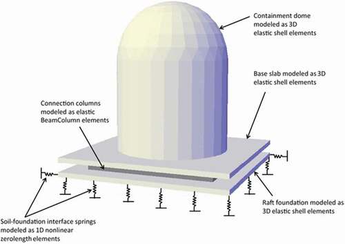
We also investigate studies on applying substructuring approaches in seismic analysis. Block et al. [Citation93] verified their 3D FEM of KK unit No. 7 by comparing simulation analysis results of a recorded earthquake with actual results. According to JEAC4601-2015, soil springs can be distributed into certain nodes of an SSI analysis model as Winkler-type soil springs, and Tokyo Electric Power Company [Citation94] conducted a simulation analysis of the reactor building of KK unit No. 4 by using a 3D FEM with Winkler springs. The simulation results matched the observed results. Because these analyses did not include nonlinear foundation uplift, we investigated studies on modeling the uplift with Winkler springs. Sako et al. [Citation95] and Hashimoto et al. [Citation96] proposed nonlinear springs to model nonlinear foundation uplift and separation of structures from soil. They validated the method by comparing centrifuge test results with analysis using an LMBM of the test specimen. Kumar et al. [Citation97] applied a substructuring approach based on nonlinear Winkler-type soil springs in seismic analysis using their 3D FEM of a containment structure (). These studies suggest that SSI including nonlinear foundation uplift can be successfully modeled using 3D FEMs of primary structures with nonlinear, Winkler-type soil springs.
Figure 8. 3D FEM of containment structure.
This figure is reprinted under the terms of the Creative Commons Attribution 4.0 International License (http://creativecommons.org/licenses/by/4.0/).
Finally, we discuss directions for future studies. Some previous studies [Citation27,Citation77–Citation83] indicate that direct approaches can be efficiently applied in seismic analysis using 3D FEMs of primary structures in Japanese NPPs. Other previous studies [Citation84–Citation90] indicate that the direct approaches with joint elements can be applied to model nonlinear foundation uplift. Moreover [Citation93–Citation97], we may be able to apply substructuring approaches with nonlinear, Winkler-type soil springs that can represent nonlinear foundation uplift. Although we can use either direct or substructuring approaches, as described above, their accuracy and efficiency have not been compared with each other. We therefore conclude that future studies should focus on comparing accuracy and efficiency to select appropriate SSI modeling approaches.
4.5. Verification and validation
4.5.1. Outline of international practices
We next outline the requirements of international guides and standards [Citation5,Citation6,Citation10,Citation17] for V&V of SSI analysis models. In NS-G-1.6 [Citation17], the IAEA requires that: (1) SSI analysis models be validated by test or comparison with other models developed with different formulations, and (2) sensitivity analyses be conducted to determine the sizes, types, and numbers of finite elements. NUREG-0800 [Citation5] requires that SSI analysis models satisfy U.S. Nuclear Regulatory Commission requirements. For example, to ensure an adequate number of discrete degrees of freedom, the document requires the following: (1) modal analysis to ensure sufficient numbers of modes and reasonably smooth mode shapes, and (2) 1G (acceleration of gravity) static analyses using SSI analysis models and comparison of the results with those of refined (more detailed) analysis models. ASCE/SEI 4-16 [Citation6] and the EUR document [Citation10] describe their own viewpoints on V&V and require sensitivity studies on certain items, such as the sizes of finite elements and time integration steps. In such sensitivity studies, differences must be within 10%, and ASCE/SEI 4-16 even states that differences within 10% are insignificant.
In accordance with these guides and standards, the V&V for 3D FEMs of novel NPPs [Citation4,Citation18–Citation22] was mainly conducted by comparing the results of SSI analysis models with those of refined analysis models. The items for comparison were the number of modes, mode shapes, and 1G static analysis results. In addition, other items were compared in some plants: transfer functions obtained from frequency response analysis [Citation20] and time history response analysis results [Citation22]. Lastly, the design certification documents [Citation4,Citation18–Citation22] demonstrated that the SSI analysis models conformed to guides and standards such as NUREG-0800 and ASCE 4-98 [Citation55].
These V&V methodologies for SSI analysis models are basically the same as those required in the NRA guide [Citation3]. Specifically, that guide requires that the validity of SSI analysis models be shown on the basis of simulation analysis of recorded earthquakes or analysis using refined models. Additionally, it requires SSI analysis models to satisfy the requirements of JEAG4601-1987 [Citation64]. Since JEAG4601-1987 mainly gives requirements for modeling with LMBMs, we would need to create standards related to modeling with 3D FEMs when we apply 3D FEMs for seismic analysis of Japanese NPPs.
4.5.2. Studies on standardization of 3D FEMs
Next, we investigate studies on standardizing 3D FEMs for NPPs in Japan. As described in Section 4.1.2, seismic analysis of primary structures must be conducted using nonlinear SSI analysis models. In particular, the material nonlinearity of the RC constituting primary structures has to be included in SSI analysis models. We therefore consider studies on standardizing modeling methods for material nonlinearity. Standardization of other aspects of 3D FEMs, besides nonlinear material modeling methods, should involve standards such as ASCE/SEI 4-16. The JEAG4601-1987 and JEAC4601-2015 documents should also contribute to standardizing 3D FEMs.
Adachi et al. [Citation98] conducted a sensitivity analysis related to mesh sizes by using a simply shaped 3D FEM with a nonlinear material model for RC and concluded that mesh sizes have to be smaller as nonlinearity increases. Umeki et al. [Citation99] likewise conducted a sensitivity analysis related to nonlinear material modeling methods for RC with a simple-shaped 3D FEM but found only a small dependency of analysis results on their modeling methods. Future studies should focus on this kind of standardization of 3D FEMs for SSI analysis models of NPPs in Japan in order to create standards for 3D FEMs.
5. Conclusion
3D FEMs have been used as SSI analysis models for seismic analysis in the design of the novel NPPs outside Japan. To organize the issues related to the development and application of 3D FEMs for seismic analysis in the design of Japanese NPPs, we investigated related international practices in terms of structural modeling, fluid modeling, damping modeling, SSI modeling, and V&V. We then investigated existing studies on those issues to suggest directions for future studies. summarizes these future directions.
Table 1. Key directions for future studies
From our investigation into international practices for structural modeling, we found that SSI analysis models can be basically composed of 3D FEMs of primary structures and LMBMs of substructures. Thus, we first need to develop 3D FEMs of primary structures. Existing studies indicate that we can develop adequate 3D FEMs of primary structures in Japanese NPPs while accounting for the RC material nonlinearity. As a next step, 3D FEMs of substructures need to be developed and used to replace LMBMs in combination with 3D FEMs of primary structures. Existing studies indicate that we can develop 3D FEMs of substructures. Seismic analysis using 3D FEMs composed of both primary structures and substructures, however, would require long calculation time. Therefore, future studies should focus on this issue to enable such seismic analysis.
Large amounts of fluids are contained in primary structures. Modeling such fluids in 3D FEMs of primary structures can be basically achieved using simplified, practical modeling methods, as seen for the novel NPPs and in some existing studies. For application of 3D FEMs, further studies on developing these kinds of fluid modeling methods should be conducted. Then, to conduct more detailed seismic analysis, future works should focus on applying sophisticated FSI analysis methods in consideration of the calculation time.
Primary structures generally have different damping properties from substructures. Composite modal damping ratios have been evaluated for such damping modeling, and damping matrices have been developed using the equivalent damping matrix for existing seismic analyses of Japanese NPPs. However, this damping modeling induces a problem for 3D FEMs. Although several alternate damping modeling methods have been proposed, further studies are necessary on: (1) more accurate damping models, such as Caughey damping for each element, and (2) effectiveness of the block damping matrix and solution methods for an equation of motion based on the incomplete damping matrix.
SSI modeling is essential in seismic analysis of the primary structures of NPPs. Such modeling using 3D FEMs of primary structures can be achieved through existing methods: the direct and substructuring approaches. The accuracy and efficiency of these approaches, however, have not been compared in 3D FEMs. Future works should thus focus on such comparison in consideration of nonlinear foundation uplift modeling.
Lastly, V&V of developed 3D FEMs is also essential for the reliability of analysis results. Such V&V can be conducted by comparing 3D FEM analysis results with analysis results from more detailed 3D FEMs. Developed 3D FEMs should also be verified to satisfy related guides and standards. No such guides or standards have been created, however, for seismic analysis of Japanese NPPs with 3D FEMs. Future works should thus focus on standardizing development procedures for these 3D FEMs and creating guides and standards.
Our study is the first of its kind to organize these issues and suggest directions for future studies related to the development and application of 3D FEMs for seismic analysis of NPPs in Japan. In general, future works should focus on resolving these issues and enabling more accurate, efficient seismic analysis using 3D FEMs. This would contribute to consolidating the seismic integrity of Japanese NPPs.
Disclosure statement
No potential conflict of interest was reported by the authors.
Related Research Data
References
- Tokyo Electric Power Company Holdings, Inc. [Kashiwazaki-Kariwa nuclear power plant unit No. 6 and 7, Prevention of damages due to earthquakes (Support documentation)]. Japan; 2016. (KK67–0100 Rev. 29). Japanese.
- Nuclear Regulation Authority. [Reviewing guide of NRA, The Guide for the design basis ground motion and seismic design policies]. Japan; 2013. Japanese.
- Nuclear Regulation Authority. [Reviewing guide of NRA, The Guide for construction application on seismic design]. Japan; 2013. Japanese.
- Westinghouse Electric Company. AP1000 Design Control Document Rev. 19 – tier 2 chapter 3 – design of structures, components, equipment and systems. USA; 2011.
- U.S. Nuclear Regulatory Commission. Standard review plan. USA; 2013. (NUREG-0800 Rev. 4).
- American Society of Civil Engineers. Seismic analysis of safety-related nuclear structures. USA; 2017. (ASCE/SEI 4-16).
- Yoshimura S, Kobayashi K, Akiba H, et al. Seismic response analysis of full-scale boiling water reactor using three-dimensional finite element method: translation. J Nucl Sci Technol. 2015;52:546–567.
- Hossain QA. Critical soil-structure interaction analysis considerations for seismic qualification of safety equipment. ASME/JSME 2004 PVP Conference; 2004 Jul 25–29; California, USA.
- Tabatabaie M, Sumodobila B, Wong C, et al. Detailed finite element modeling of US EPR™ nuclear island for seismic SSI analysis. ASME 2010 PVP Div./K-PVP Conference; 2010 July 18–22; Washington, USA.
- EUR organization. European utility requirements for LWR nuclear power plants. Rev D. 2012.
- Choi Y, Park JB, Lee SJ, et al. Seismic analysis of the APR 1400 reactor vessel internals using the model reduction method. J Nucl Sci Technol. 2016;53:1701–1714.
- Zhao C, Chen J, Xu Q. Dynamic analysis of AP1000 shield building for various elevations and shapes of air intakes considering FSI effects subjected to seismic loading. Prog Nucl Ene. 2014;74:44–52.
- Tuñón-Sanjur L, Orr RS, Tinic S, et al. Finite element modeling of the AP1000 nuclear island for seismic analyses at generic soil and rock sites. Nucl Eng Des. 2007;237:1474–1485.
- Torkian BB, Chandran P, Ratnagaran BJ, et al. Validation of lumped mass stick models for surface founded structures. SMiRT-22; 2013 Aug 18–23; California, USA.
- Tinic S, Orr R. Finite element modeling of AP1000 nuclear island. SMiRT-17; 2003 Aug 17–22; Prague, Czech Republic.
- Viallet E, Labbe P, Gallitre E, et al. Seismic re-evaluation of EDF Bugey 900 PWR nuclear power plant in the frame of the 3rd periodic safety review. Nucl Eng Des. 2010;240:1306–1319.
- International Atomic Energy Agency. Seismic design and qualification for nuclear power plants. Austria; 2003. (NS-G-1.6).
- Areva NP, Inc. Areva Design control document Rev. 5 – tier 2 chapter 3 – design of structures, components, equipment and systems. 2013.
- Mitsubishi Heavy Industries, Ltd. Design control document for the US-APWR chapter 3 design of structures, systems, components, and equipment. 2013. (MUAP-DC003 Rev. 4).
- Mitsubishi Heavy Industries, Ltd. Soil-structure interaction analyses and results for the US-APWR standard plant (non-proprietary version). 2012. (MUAP-10006 Rev. 3).
- Korea Electric Power Corp. and Korea Hydro & Nuclear Power Co., Ltd. APR1400 Design control document tier 2 chapter 3 design of structures, systems, components, and equipment. 2014. (APR1400-K-X-FS-14002-NP Rev. 0).
- Korea Electric Power Corp. and Korea Hydro & Nuclear Power Co., Ltd. Finite element seismic models for SSI analyses of the NI buildings. 2014. (APR1400-E-S-NR-14002-NP Rev. 0).
- Pinto F, Ceballos MA, Rocca RJ, et al. Validation of numerical model of Embalse nuclear power plant based on free field and in-house records of a seismic event. SMiRT-19; 2007 Aug 12–17; Tronto, Canada.
- Nour A, Cherfaoui A, Gocevski V, et al. Probabilistic seismic safety assessment of a CANDU 6 nuclear power plant including ambient vibration tests: case study. Nucl Eng Des. 2016;304:125–138.
- Rangelow P, Schütz W, Nincic V, et al. Evaluation of the behavior of a nuclear power plant structure under beyond-design seismic loading. SMiRT-22; 2013 Aug 18–23; San Francisco, USA.
- Moore J, Schneeberger C, Zinn R, et al. Earthquake response analysis in the context of the KARISMA benchmark project. SMiRT-22; 2013 Aug 18–23; San Francisco, USA.
- Hijikata K, Kikuchi R, Nukui Y, et al. [Three dimensional response behavior of unit No. 5 reactor building subjected to the Niigataken Chuetsu-oki earthquake in 2007]. J Struct Constr Eng AIJ. 2010;75:2179–2187. Japanese.
- Kasuga Y, Tunashima N, Ozaki M, et al. [Analytical study on non-linear seismic behavior of a large scale reinforced concrete structure]. J Struct Eng. 2003 Mar;49B:193–202. Japanese.
- Ueda M, Seya H, Ohmiya Y, et al. Nonlinear analysis on RC shear wall shaking table test. SMiRT-14; 1997 Aug 17–22; Lyon, France.
- Hasegawa T, Kumagai H, Irino K, et al. Seismic analysis of a RC shear wall. SMiRT-14; 1997 Aug 17–22; Lyon, France.
- Inoue N, Yang K. Dynamic nonlinear analysis of 3-D RC shear wall by finite element method. 11th WCEE; 1996 Jun 23–28; Acapulco, Mexico.
- Hibino K, Nanba H, Motohashi S, et al. Non-Liner response analysis of nuclear facilities subject to horizontal and vertical ground motions. 14th WCEE; 2008 Oct 12–17; Beijing, China.
- Nakamura N, Suzuki S, Fushimi M, et al. Study on modeling error in strong nonlinear area of RC shear walls in fragility evaluation of nuclear power plant buildings. 10th ICOSSAR; 2009 Sep 13–17; Osaka, Japan.
- Naganuma K, Kurimoto O, Eto H. [Finite element analysis of reinforced concrete walls subjected to reversed cyclic and dynamic loads]. J Struct Constr Eng AIJ. 2001 Jun;544:125–132. Japanese
- Naganuma K, Yonezawa K, Kurimoto O, et al. Simulation of nonlinear dynamic response of reinforced concrete scaled model using three-dimensional finite element method. 13th WCEE; 2004 Aug 1–6; Vancouver, Canada.
- Ono H, Kitada Y, Shintani K, et al. [Analytical study on strength and ductility of 3-dimensional shear wall subjected to horizontal two directional loading]. J Struct Constr Eng AIJ. 2004 Nov;585:139–146. Japanese.
- Yabuuchi K, Morikawa H, Suzuki A, et al. Simulation analysis of shaking table test for RC seismic shear wall in multi-axis loading tests. 13th WCEE; 2004 Aug 1–6; Vancouver, Canada.
- Torita H, Ozaki R, Shirai N. [Evaluation of ultimate capacity of RC box shear wall by nonlinear 3-D finite element dynamic analysis]. J Struct Constr Eng AIJ. 2007;612:147–153. Japanese.
- Syed S, Gupta A. Seismic fragility of RC shear walls in nuclear power plant part 2: influence of uncertainty in material parameters on fragility of concrete shear walls. Nucl Eng Des. 2015;295:587–596.
- Richard B, Martinelli P, Voldoire F, et al. SMART 2008: overview, synthesis and lessons learned from the international benchmark. Eng Struct. 2016;106:166–178.
- Richard B, Voldoire F, Fontan M, et al. SMART 2013: lessons learned from the international benchmark about the seismic margin assessment of nuclear RC buildings. Eng Struct. 2018;161:207–222.
- Zinn R, Borgerhoff M, Van Exel C, et al. Challenges faced during the modelling, dynamic analysis, and vulnerability study with SOFiSTiK in the context of the SMART 2013 benchmark project. SMiRT-23; 2015 Aug 10–14; Manchester, UK.
- Zinn R, Borgerhoff M, Van Exel C, et al. Measured vs computed strains and cracks of the SMART 2013 benchmark test specimen subjected to high earthquake excitation. SMiRT-24; 2017 Aug 20–25; Busan, South Korea.
- Kumagai T, Ogata Y, Hirotani K, et al. Simulation analysis using 3-D nonlinear FEM model for Onagawa Unit 2 control building at the time of the 2011 off the Pacific coast of Tohoku earthquake. SMiRT-23; 2015 Aug 10–14; Manchester, UK.
- Sato H, Otani S, Suzuki K, et al. Analysis and evaluation of seismic proving test of BWR core internals. SMiRT-10; 1989 Aug 22–27; Anaheim, USA.
- Yoshimura S, Yamada T, Koide Y, et al. Full scale simulation-based study on dynamic response of BWR fuel assemblies under seismic loading. ASME 2015 PVP Conference; 2015 Jul 19–23; Boston, USA.
- Park JB, Choi Y, Lee SJ, et al. Modal characteristic analysis of the APR1400 nuclear reactor internals for seismic analysis. Nucl Eng Technol. 2014;46:689–698.
- Choi Y, Lim S, Ko BH, et al. Dynamic characteristics identification of reactor internals in SMART considering fluid–structure interaction. Nucl Eng Des. 2013;255:202–211.
- Tong LL, Duan R, Cao XW. Seismic analysis of RCS with finite element model for advanced PWR. Prog Nucl Ener. 2015;79:142–149.
- Perov S, Altstadt E, Werner M. Vibration analysis of the pressure vessel internals of WWER-1000 type reactors with consideration of fluid–structure interaction. Ann Nucl Ener. 2000;27:1441–1457.
- Yamada T, Yoshimura S. Seismic response simulation of nuclear power plant. In: High-performance computing for structural mechanics and earthquake/tsunami engineering. Switzerland: Springer International Publishing; 2016. p. 141–155.
- Hori M, Ichimura T, Fujita K. Simulation of seismic wave propagation and amplification. In: High-performance computing for structural mechanics and earthquake/tsunami engineering. Switzerland: Springer International Publishing; 2016. p. 23–70.
- Tang Y, Grandy C, Seidensticker R. Seismic response of annular cylindrical tanks. Nucl Eng Des. 2010;240:2614–2625.
- Lockheed Aircraft Corp. and Holmes & Narver, Inc. Nuclear reactors and earthquakes. USA: Atomic Energy Commission; 1963. (TID-7024).
- American Society of Civil Engineers. Seismic analysis of safety-related nuclear structures. USA; 2000. (ASCE 4-98).
- Zhao C, Chen J, Xu Q. FSI effects and seismic performance evaluation of water storage tank of AP1000 subjected to earthquake loading. Nucl Eng Des. 2014;280:372–388.
- Zhao C, Chen J, Xu Q, et al. Investigation on sloshing and vibration mitigation of water storage tank of AP1000. Ann Nucl Ener. 2016;90:331–342.
- Xu Q, Chen J, Zhang C, et al. Dynamic analysis of AP1000 shield building considering fluid and structure interaction effects. Nucl Eng Technol. 2016;48:246–258.
- Rydell C, Gasch T, Facciolo L, et al. Interaction between structure and water in seismic analyses of nuclear facilities. SMiRT-22; 2013 Aug 18–23; San Francisco, USA.
- Onitsuka S, Goto Y, Iijima T, et al. Practical modeling of fluid in ABWR suppression pool for seismic analysis using 3D FEM model. Mech Eng J. 2017;4:17–00152.
- Onitsuka S, Goto Y, Ojima N, et al. Practical modeling of fluid in ABWR spent fuel pool for seismic analysis using 3D FEM model. Nucl Eng Des. 2018;331:238–247.
- Clough RW. Analysis of structural vibrations and dynamic response. In: Recent advances in matrix methods of structural analysis and design. Alabama: University of Alabama Press; 1971. p. 441–486.
- Wilson EL, Penzien J. Evaluation of orthogonal damping matrices. Inter J Nume Meth Eng. 1972;4:5–10.
- Survey Committee for Electrotechnical Standard of the Japan Electric Association. [Technical guidelines for aseismic design of nuclear power plants]. Japan; 1987. (JEAG4601-1987). Japanese.
- Onitsuka S, Ushio Y, Ojima N, et al. Modeling method of element Rayleigh damping for the seismic analysis of a 3D FEM model with multiple damping properties. J Vib Contr. 2018;24:4065–4077.
- Wang J. Rayleigh coefficients for series infrastructure systems with multiple damping properties. J Vib Contr. 2015;21:1234–1248.
- Puthanpurayil AM, Lavan O, Carr AJ, et al. Elemental damping formulation: an alternative modelling of inherent damping in nonlinear dynamic analysis. Bull Earthquake Eng. 2016;14:2405–2434.
- Nakamura N. Extended Rayleigh damping model. Front Built Environ. 2016;2.
- Yoshida K, Hama I, Uchikoshi K, et al. [Method of formation of damping matrix for large soil-structure-machinery system model]. Annual Meeting AIJ; 1985 Oct; Tokai, Japan. Japanese.
- Yanagawa Y, Suzuki S, Usami M, et al. [Proposed a high-speed solution of modal damping using the incomplete damping matrix]. Annual Meeting AIJ; 2014 Sep 12–14; Kobe, Japan. Japanese.
- Yanagawa Y, Suzuki S, Usami M, et al. [Verification of high-speed solution of modal damping using the incomplete damping matrix]. Annual Meeting AIJ; 2015 Sep 4–6; Hiratsuka, Japan. Japanese.
- ACS SASSI [Internet]. USA: Ghiocel Predictive Technologies, Inc.; 2018 [cited 2018 Jan 14]. Available from: http://www.ghiocel-tech.com/engineering-tools.
- SASSI 2000. A system for analysis of soil-structure interaction [Internet]. USA: Pacific Earthquake Engineering Research Center; 2018 [cited 2018 Jan 14]. Available from: https://nisee.berkeley.edu/elibrary/Text/200703021
- MTR/SASSI SSI Software [Internet]. USA: MTR & Associates, Inc.; 2018 [cited 2018 Jan 14]. Available from: http://mtrassoc.com/mtrsassi/
- SHAKE-91 Software and Manuals [Internet]. USA: Pacific Earthquake Engineering Research Center; 2018 [cited 2018 Jan 14]. Available from: https://nisee.berkeley.edu/elibrary/getpkg?id=SHAKE91
- Nuclear Standards Committee of the Japan Electric Association. [Technical codes for aseismic design of nuclear power plants]. Japan; 2017. (JEAC4601-2015). Japanese.
- Kabanda J, Kwon OS, Kwon G. Time and frequency domain analyses of the Hualien large-scale seismic test. Nucl Eng Des. 2015;295:261–275.
- Wang F, Rambach JM. Contribution to the IAEA soil-structure interaction KARISMA benchmark. SMiRT-22; 2013 Aug 18–23; San Francisco, USA.
- Nakamura N. Nonlinear response analyses of a soil–structure interaction system using transformed energy transmitting boundary in the time domain. Soil Dyn Earth Eng. 2009;29:799–808.
- Nakamura N. Three-dimensional energy transmitting boundary in the time domain. Front Built Environ. 2015;1.
- Akita S, Nakamura N, Kudo W, et al. [A study on time domain energy transmitting boundary for improving efficiency of calculation and application to detail soil-structure interaction system]. J Struct Constr Eng AIJ. 2013;78:1263–1272. Japanese.
- Takahashi Y, Morita N, Saka T, et al. Large-scale parallel computing performance of finite element analyses for reactor building incorporating soil-structure interaction. SMiRT-24; 2017 Aug 20–25; Busan, South Korea.
- Tanaka S, Ichimura T, Hori M, et al. [Development of earthquake response analysis method for large-scale soil and complex structure interaction problem with high fidelity model]. J JSCE (Ser A2). 2014;70:p.I_613–I_620. Japanese.
- Hijikata K, Kikuchi R, Nukui Y, et al. [Dynamic response of unit No. 7 reactor building during the Niigataken Chuetsu-oki earthquake in 2007]. J Struct Constr Eng AIJ. 2011;76:319–327. Japanese.
- Nakamura N, Ino S, Kurimoto O, et al. An estimation method for basemat uplift behavior of nuclear power plant buildings. Nucl Eng Des. 2007;237:1275–1287.
- Nakamura N, Yabushita N, Suzuki T, et al. Analyses of reactor building by 3D nonlinear FEM models considering basemat uplift for simultaneous horizontal and vertical ground motions. Nucl Eng Des. 2008;238:3551–3560.
- Nakamura N, Inoda K, Suzuki T, et al. [Study on induced vertical motion due to basemat uplift of building during severe earthquake]. J Struct Constr Eng AIJ. 2016 ;81:525–535. Japanese.
- Ogase Y, Takada A, Honda T, et al. Centrifuge testing and seismic response analysis for uplift behavior of spread foundation structures on rock. SMiRT-24; 2017 Aug 20–25; Busan, South Korea.
- Kawasato T, Okutani T, Kurimoto O, et al. A study on evaluation of seismic response considering basemat uplift for soil-building system using 3D FEM. SMiRT-19; 2007 Aug 12–17; Tronto, Canada.
- Kawasato T, Okutani T, Ishikawa T, et al. Experimental study of seismic soil-structure interaction by using large geotechnical centrifuge system. 14th WCEE; 2008 Oct 12–17; Beijing, China.
- Choi B, Nishida A, Nakajima N. [A sensitivity analysis for construction of the seismic response analysis model of a nuclear reactor building by using a three-dimensional finite element model]. J Struct Eng AIJ. 2017;63B. Japanese.
- Datta D, Varma AH, Seo J, et al. Investigation of interface non-linearity on soil-structure interaction analyses. SMiRT-24; 2017 Aug 20–25; Busan, South Korea.
- Block C, Henkel FO, Weber F. Seismic margin assessment of a reactor building. SMiRT-22; 2013 Aug 18–23; San Francisco, USA.
- Tokyo Electric Power Company. [Simulation analysis of Chuetsu-oki earthquake on reactor building unit No. 4 – additional investigation – (Rev. 2)]. Japan; 2008. (Kozo W19-4-2). Japanese.
- Sako Y, Imamura A, Hashimoto T, et al. [Study on nonlinear and uplift behavior of structure under huge earthquake, Part 3: verification analyses using simplified lumped-mass model]. Annual Meeting AIJ; 2013 Aug 30–Sep 1; Sapporo, Japan. Japanese.
- Hashimoto T, Imamura A, Suko Y, et al. [Study on nonlinear and uplift behavior of structure under huge earthquake, Part 4: verification of simplified lumped-mass model]. Annual Meeting AIJ; 2013 Aug 30–Sep 1; Sapporo, Japan. Japanese
- Kumar S, Raychowdhury P, Gundlapalli P. Response analysis of a nuclear containment structure with nonlinear soil–structure interaction under bi-directional ground motion. Int J Adv Struct Eng. 2015 Jun;7:211–221.
- Adachi T, Imamura A, Shinki Y, et al. [Study on the difference of elasto-plastic response due to FEM mesh size (Part 2: comparison of nonlinear dynamic analysis results)]. Annual Meeting AIJ; 2011 Aug 23–25; Tokyo, Japan. Japanese.
- Umeki Y, Adachi T, Sugita H, et al. [Study on advanced seismic design methods with 3-D FEM model: (Part 1) investigation of nonlinear response analysis methods]. Annual Meeting AIJ; 2014 Sep 12–14; Kobe, Japan. Japanese.