
 ?Mathematical formulae have been encoded as MathML and are displayed in this HTML version using MathJax in order to improve their display. Uncheck the box to turn MathJax off. This feature requires Javascript. Click on a formula to zoom.
ABSTRACT
Heat transfer study of nanofluids as coolant in SCWRs core has been performed at Helwan University. A thermal hydraulic code has been produced to study the effect of TiO2 nanofluid water based as a coolant with comparison with pure water as a coolant. Various volume fractions of nanoparticles TiO2 (2, 6 and 10%) were used in order to investigate its effects on reactor thermalhydraulic characteristics. Based on Parameters of a SCW Canadian Deuterium Uranium nuclear reactor (CANDU), the fuel assembly was modeled to study the effect of nanoparticles volume fraction on thermos-physical properties of basic fluid and the temperature distribution of fuel, cladding surface and coolant in axial direction. The theoretical results showed that the density, viscosity and thermal conductivity of the coolant increases with the increase of nanoparticles volume fraction, contrasting to specific heat, which decreases with the increase in nanoparticles volume fraction.
Thermal conductivity increases with 2, 6 and 10% volume fraction of nanoparticles by 5.5, 18.1 and 32.1%, respectively, at constant pressure 25 (MPa). For 10% volume percentage of nanoparticles the coolant temperature difference with pure water is about 24.2°C, 62.5°C and 94°C at constant pressure 25, 30 and 35 (MPa), respectively. On the other hand, using nanofluid with 10% volume percentage of nanoparticles as coolant has significant effect on fuel temperature that the maximum fuel temperature reduced by 26.2, 23.8 and 18.9% at constant pressure 25, 30 and 35 (MPa), respectively.
1. Introduction
Recent advancements in nanotechnology have originated the new emerging heat transfer fluids called nanofluids. Nanofluids are prepared by dispersing and stably suspending nanometer-sized solid particles in conventional heat transfer fluids. Previous researches have shown that a very small amount of suspending nanoparticles have the potential to enhance the thermophysical, transport and radiative properties of the base fluid. Due to improved properties, better heat transfer performance is obtained in many energy and heat transfer devices as compared to traditional fluids, which open the door for a new field of scientific research and innovative applications [Citation1].
Nanofluids clearly exhibit improved thermo-physical properties such as thermal conductivity, thermal diffusivity, viscosity and convective heat transfer coefficient. The property change of nanofluids depends on the volumetric fraction of nanoparticles, shape and size of the nanomaterials [Citation2,Citation3].
Thermal hydraulic effects of nanofluid as coolant in VVER-1000 nuclear reactor with annular fuel are investigated. The fuel assembly has been simulated in the hot channel using computational fluid dynamics (CFD) simulation codes, and thermalhydraulic calculations (maximum fuel temperature, fluid outlet, minimum departure from nucleate boiling ratio (MDNBR) etc.) are done. As one of the most important results of the analysis, using the nanoparticles increases the heat transfer coefficient [Citation4].
Analytical modeling [Citation5] of the thermalhydraulic in small modular reactor (SMR) CAREM-25 has been applied when the Al2O3-water-based nanofluid is used as cooling fluid in the cooling system. Further to this analytical modeling, the reactor has been modeled by using CFD to determine the flow phenomena and distribution as well as the effect of nanoparticles of Al2O3-water based on the volume fraction (1 and 3%) on the heat transfer by natural convection.
SCWR reactor thermalhydraulic analysis with a new geometry design has been discussed [Citation6,Citation7]. In the new design, coolant and moderator circuits are separated and nanofluid has been used as reactor core coolant. The thermalhydraulic analysis has been performed for various Al2O3 nanoparticles mass fraction and moderator velocities. The calculations showed that the core outlet temperature grows up with increasing nanoparticle mass fraction.
VVER-1000 reactor cooled by Al2O3 nanofluid has been studied. The effects of fluctuations in coolant temperature and velocity at the inlet of a fuel assembly have been investigated. The analysis were performed by using a Fourier transformed conservation equation (mass, momentum and energy) in frequency space. The thermalhydraulic effects of nanofluid on noise fluctuations were calculated based on different concentrations of Al2O3 nanoparticles and noise frequencies. The calculations showed that any increment in nanoparticles mass fraction will result in reduction of fluctuations in coolant temperature and velocity [Citation8].
1.1 Supercritical water cooled nuclear reactors
SuperCritical Water-cooled nuclear Reactors (SCWRs) are a renewed technology being pursued as one of the six Generation IV International Forum (GIF) reactor concepts. The reactor coolant is light water at pressures and temperatures above its critical point. Some fossil generation power plants use SuperCritical Water (SCW) as the working fluid. However, SCWRs are the only Generation IV reactor concept to be cooled with SCW. These elevated operating conditions will improve SCW Nuclear Power Plant (NPP) thermal efficiency by 10–15% compared to those of current NPPs. Also, SCWRs will have the ability to employ a direct cycle, thus decreasing NPP capital and maintenance costs. A demonstration unit has yet to be designed and constructed. Fuel materials and configurations suited to supercritical conditions are currently being studied. Typical SCWR coolant operating parameters are 25 MPa and 350–625°C. These SCWR operating conditions significantly increase the thermal efficiency of current NPPs from 33–35% to approximately 45–50% [Citation9,Citation10,Citation11,Citation12,Citation13,Citation14,Citation15,Citation16].
1.2 Fuel bundle geometry
) shows the fuel bundle, which consists of a heated length of 5.772 m. The central rod has an outer diameter (OD) of 20 mm and is assumed to be unheated. The remaining 42 elements have the OD of 11.5 mm. The hydraulic-equivalent diameter of the bundle is 7.83 mm [Citation9].
Figure 1. Fuel bundle geometry [Citation9].
![Figure 1. Fuel bundle geometry [Citation9].](/cms/asset/e4c7bef0-3e20-4810-ab38-3168bccc5565/tnst_a_1571452_f0001_b.gif)
2. Mathematical model and validation
In current study the considered design parameters showned in has been used in the calculations and the considered nanofluid is a mixture of water and nanoparticles of TiO2. illustrate thermos-physical properties of TiO2.
Table 1. Major parameters of SCW-CANDU and channel reactor with supercritical pressure water [Citation10]
Table 2. Density-specific thermal conductivity of TiO2.
EquationEquations (1(1)
(1) )–(Equation5
(5)
(5) ) were used to study the effect of using nanofluid as a coolant in supercritical condition on coolant thermos-physical properties and temperature distribution across fuel rod.
Correlation (1) is used to calculate density of TiO2 [Citation6,Citation17,Citation18,Citation19],
where ρnf is the density of the nanofluid, ϕ is the volume fraction of the nanofluid, ρbf is the density of the base fluid and ρp is the density of particle.
Correlation (2) is used to calculate Specific heat of TiO2 [Citation6,Citation17,Citation18,Citation19].
where Cpnf is the specific heat of the nanofluid, Cpbf is the specific heat of the base fluid and (Cp)p is the specific heat of the nanoparticle.
Correlation (3,4) is used to calculate viscosity of TiO2 [Citation6,Citation17,Citation18,Citation19].
where μnf is the viscosity of the nanofluid, μbf is the viscosity of the base fluid.
Correlation (5) is used to calculate conductivity of TiO2 [Citation18].
where Knf is the thermal conductivity of the nanofluid, Knp is the thermal conductivity of the nanoparticle, Kbf is the thermal conductivity of the base fluid and is the ratio of the monolayer thickness to the original particle radius, normally
= 1.
The coolant temperature distribution can be calculated using EquationEquation (6)(6)
(6) [Citation20,Citation21].
where Tc,z is the axial coolant temperature, Tc,i is the coolant inlet temperature, qi is the maximum heat flux rate, Li is the full heated length of the fuel rod, He is the extrapolated length, Cp-nano is the specific heat of the nanofluid, is the coolant mass flow rate and z is the fuel increment.
The cladding outer surface temperature distribution can be calculated using EquationEquation (7)(7)
(7) [Citation20,Citation21].
TCL,Z is the axial cladding surface temperature, TC.i is the Coolant inlet temperature and h is the heat transfer coefficient.
The fuel temperature distribution was calculated using EquationEquation (8)(8)
(8) [Citation20,Citation21]., thus
where Tf,Z is the axial center line fuel temperature and Rt is the total thermal resistance.
EquationEquation (9)(9)
(9) is used to calculate the maximum heat flux rate (
) [Citation21].
where Q is the thermal power and Ah is the heated area.
EquationEquation (10)(10)
(10) is used to calculate the heated area (
) [Citation21].
where D_i is the diameter of the heated fuel rod, N_assm is the number of fuel assemblies and N_fuel_pin is the number of fuel pins in the assemblies.
EquationEquation (11)(11)
(11) , is used to calculate the flow area (
) [Citation21].
where Af is the coolant channel flow area, Apt is the pressure tube area and Afb is the fuel bundle area.
EquationEquation (12)(12)
(12) , is used to calculate the pressure tube area (
) [Citation21],
where di is the flow tube inner diameter.
EquationEquation (13)(13)
(13) , is to calculate the wetted perimeter (
) [Citation21].
where Pwetted is the wetted perimeter, N_fuel_pin is the number of fuel pins in the assemblies and db is the flow bundle diameter.
EquationEquation (14)(14)
(14) , is used to calculate the hydraulic diameter (
) [Citation21].
where Dhy is the hydraulic diameter.
EquationEquation (15)(15)
(15) is used to calculate the fuel bundle area (
) [Citation21].
EquationEquation (16)(16)
(16) is used to calculate the Reynolds number of coolant (
) [Citation20].
where Re-nano is the Reynolds number for nanofluid, G is the mass flux.
EquationEquation (17)(17)
(17) is used to calculate the Prandtle number of nanofluid/water-based coolant (
) [Citation17].
Pr-nano is the Prandtl number of coolant.
EquationEquation (18)(18)
(18) is used to calculate the mass flux (
) [Citation21].
Total thermal resistance () is the sum of thermal resistance of cladding (
), thermal resistance of coolant (
) and thermal resistance of fuel (
).
EquationEquation (20)(20)
(20) can be used to calculate the thermal resistance of cladding (
) [Citation22].
where rf is the outer radius of fuel.
The outer radius of cladding () is the sum of cladding thickness (
) and the outer radius of fuel (
).
The thermal conductivity of SS-304 is calculated using EquationEquation (22)(22)
(22) [Citation21].
where Kc is the cladding thermal conductivity, T is the Mean temperature of coolant.
The thermal resistance of nanofluid water-based coolant () can be calculated using EquationEquation (23)
(23)
(23) .
EquationEquation (24)(24)
(24) is used to calculate the heat transfer coefficient of nanofluid water-based coolant (
) [Citation17].
EquationEquation (25)(25)
(25) is used to calculate Nusselt number (
) [Citation17].
EquationEquation (26)(26)
(26) can be used to calculate the thermal resistance of fuel (
).
where Kf is the thermal conductivity of nuclear fuels.
3. Results and discussion
In this study, nanofluids TiO2 -Water with 2, 6 and 10% volume percentages of nanoparticles have been modeled in the supercritical reactor and the thermophysical properties of nanofluids have been investigated.
shows the validation of pure water density between current model and the results of Ref. [Citation23] at supercritical pressure of 25 (MPa).It can be seen that the comparisons showed a good agreement with the data of Ref. [Citation23] for temperature range from 350 (°C) to 400 (°C).
Figure 2. Pure water density at supercritical pressure 25 (MPa) compared with Ref. [Citation23].
![Figure 2. Pure water density at supercritical pressure 25 (MPa) compared with Ref. [Citation23].](/cms/asset/7e658b87-76a2-46e3-9636-9f5294c3c9af/tnst_a_1571452_f0002_oc.jpg)
shows the validation of pure water specific heat between current model and Ref. [Citation23] results at supercritical pressure of 25 (MPa). It can be seen that the comparisons showed a good agreement with maximum absolute deviations of (2.4%) with the data of Ref. [Citation23] at temperature range from 350 (°C) to 400 (°C).
Figure 3. Pure water specific heat at supercritical pressure 25 (MPa) between current model and Ref. [Citation23].
![Figure 3. Pure water specific heat at supercritical pressure 25 (MPa) between current model and Ref. [Citation23].](/cms/asset/64a87246-75f0-4131-abe9-e640a173de4c/tnst_a_1571452_f0003_oc.jpg)
shows the validation of pure water viscosity between current model and Ref. [Citation23] results at supercritical pressure of 25 (MPa). It can be seen that the comparisons showed a good agreement with the Ref. [Citation23] data at temperature range from 350 (°C) to 400 (°C).
Figure 4. Pure water viscosity at supercritical pressure 25 (MPa) compared with Ref. [Citation23].
![Figure 4. Pure water viscosity at supercritical pressure 25 (MPa) compared with Ref. [Citation23].](/cms/asset/7e7672d4-1e75-4316-b594-636ec7945267/tnst_a_1571452_f0004_oc.jpg)
In and the current model nanofluid results at supercritical pressure 25 (MPa) ware compared with Ref. [Citation24]. That results of LWR with 15 (MPa) pressurized water reactor cooled by nanofluid were used for validation. As there are no thermal properties of supercritical nanofluid water-based coolant in the literature. Comparisons illustrate good agreement in coolant profile taking into consideration the difference in operating conditions.
Figure 5. Coolant temperature distribution in axial direction compared with Ref. [Citation24] at ϕ 6%.
![Figure 5. Coolant temperature distribution in axial direction compared with Ref. [Citation24] at ϕ 6%.](/cms/asset/b6e7339d-35b8-4f8c-96c4-96c01e20e901/tnst_a_1571452_f0005_oc.jpg)
Figure 6. Coolant temperature distribution in axial direction compared with Ref. [Citation24] at ϕ 10%.
![Figure 6. Coolant temperature distribution in axial direction compared with Ref. [Citation24] at ϕ 10%.](/cms/asset/e20d37b2-5cb3-411f-bba7-dd2de253cb33/tnst_a_1571452_f0006_oc.jpg)
illuminates the temperature distribution of coolant along heated length of supercritical nuclear reactor cooled by nanofluid. Increasing volumetric ratio of TiO2 particles at constant supercritical pressure P = 25 (MPa), increases the temperature of coolant along heated length. The maximum coolant temperature is as illustrated in .
Table 3. Maximum coolant temperature difference between SCWR cooled with pure water and SCWR cooled with TiO2 -water nanofluid at P = 25 (MPa)
Figure 7. Coolant temperature at constant pressure 25 (MPa) different volume fractions of TiO2 particles.
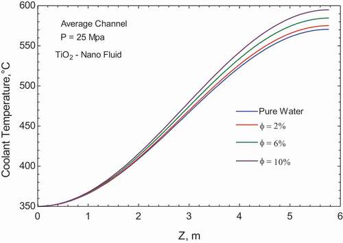
It can be seen that for volume percentage (ϕ = 10%) of nanoparticles, the coolant temperature difference with pure water is about 24.2 (°C). This means that the heat exchange capacity of the supercritical coolant increased. Thus, to preserve equal design temperature difference, lower coolant flow rate is necessary for cooling the reactor core. Consequently, the reactor core can be more compact and the capital cost of the power plant will be reduced. This temperature difference can save reheat unit cost, which matches with Ref. [Citation24] results.
illuminates the temperature distribution of coolant along heated length of supercritical nuclear reactor cooled by nanofluid. Increasing volumetric ratio of TiO2 particles at constant supercritical pressure P = 30 (MPa), increases the temperature of coolant along heated length. The maximum coolant temperature is as illustrated in .
Table 4. Maximum coolant temperature difference between SCWR cooled with pure water and SCWR cooled with TiO2 -water nanofluid at P = 30 (MPa)
Figure 8. Coolant temperature at constant pressure 30 (MPa) different volume fractions of TiO2 particles.
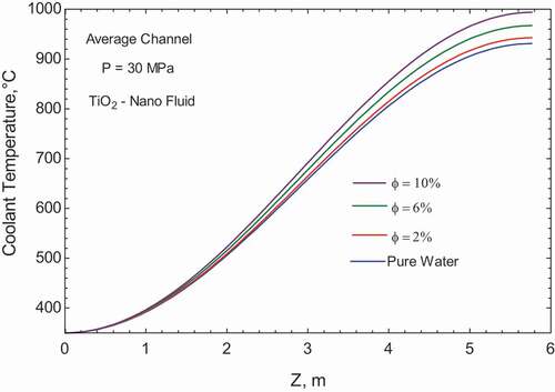
It can be seen that for volume percentage (ϕ = 10%) of nanoparticles, the coolant temperature difference with pure water is about 62.7 (°C). This means that the heat exchange capacity of the supercritical coolant increased.
lights up the temperature distribution of coolant along heated length of supercritical nuclear reactor cooled by nanofluid. Increasing volumetric ratio of TiO2 particles at constant supercritical pressure, P = 35 (MPa), increases the temperature of coolant along heated length. The maximum coolant temperature is as illustrated in .
Table 5. Maximum coolant temperature difference between SCWR cooled with pure water and SCWR cooled with TiO2 -water nanofluid P = 35 (MPa)
Figure 9. Coolant temperature at constant pressure 35 (MPa) different volume fractions of TiO2 particles.
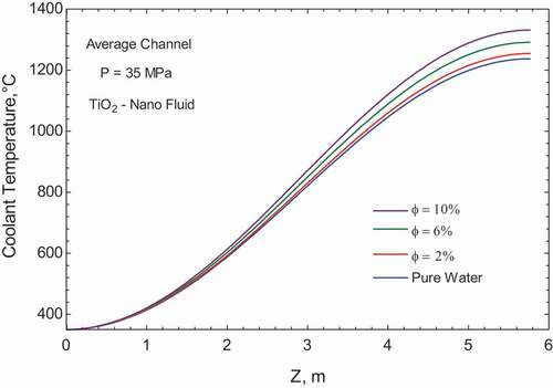
It can be seen that for volume percentage, (ϕ = 10%) of nanoparticles, the coolant temperature difference with pure water is about 94 (°C). This means that the heat exchange capacity of the supercritical coolant increased.
illuminates the temperature distribution of fuel along heated length of supercritical nuclear reactor cooled by nanofluid. Increasing volumetric ratio of TiO2 particles at constant supercritical pressure P = 25 (MPa), decreases the temperature of fuel along heated length. The maximum fuel temperature is as illustrated in .
Table 6. Maximum fuel temperature difference between SCWR cooled with pure water and SCWR cooled with TiO2-water nanofluid at P = 25 (MPa)
Figure 10. Fuel temperature at constant pressure 25 (MPa) different volume fractions of TiO2 particles.
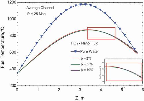
clear up the maximum fuel temperature reduction with increasing nanoparticle volumetric ratio at constant supercritical pressure.
The fuel temperature distribution of the supercritical nuclear reactor cooled by nanofluid will have an extra safe margin 308.5 (°C). That reducing the probability to exceed the industrial acceptance temperature limit of 1850 (°C).
From at constant pressure 25 (MPa), using water-based nanofluid as coolant has significant effect on fuel temperature that it reduced by 26.2% accordingly, using nuclear fuels with low melting point can be available and safe with nanofluids . Also it can be seen that for 6 and 10% volume percentage of nanoparticles the fuel temperature reduction is drastically deteriorated. It is because the reduction in specific heat that occur with increasing nanoparticles, and the increase in coolant temperature, which can also explain the propagation of maximum fuel temperature across the fuel rod to be near the end of heated length.
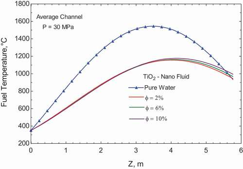
shows the temperature distribution of fuel along heated length of supercritical nuclear reactor cooled by TiO2 nanofluid. In the case of cooling the reactor by pure water, the maximum fuel temperature reaches to 1545 (°C). By adding the TiO2 with volume fraction of 2%, (ϕ = 2%) the maximum fuel temperature decreases to 1158 (°C). By increasing the volume fraction percentage, the fuel temperature almost constant and did not affected with these increase as illustrated in . On the contrary, the maximum fuel temperature tend to increase by increasing the volume fraction percentage after 3.8 (m) of the heated length, i.e. the adding nanoparticles to the pure water enhance the heat transfer coefficient till a certain limit after this limit the maximum fuel temperature tend to increase due to deterioration in the heat transfer.
Figure 11. Fuel temperature at constant pressure 30 (MPa) different volume fractions of particles.
clear up the maximum fuel temperature reduction with increasing nanoparticle volumetric ratio at constant supercritical pressure.
Table 7. Maximum fuel temperature difference between SCWR cooled with pure water and SCWR cooled with TiO2 -water nanofluid at P = 30 (MPa)
The fuel temperature distribution of the supercritical nuclear reactor cooled by nanofluid will have an extra safe margin 387 (°C). That reduces the probability to exceed the industrial acceptance temperature limit of 1850 (°C).
From at constant pressure 30 (MPa), using water-based nanofluid as coolant has significant effect on fuel temperature that it reduced by 26.2% accordingly, using nuclear fuels with low melting point can be available and safe with nanofluids . Also it can be seen that for 6 and 10% volume percentage of nanoparticles the fuel temperature reduction is drastically deteriorated. It is because of the reduction in specific heat that occurs with increasing nanoparticles, and the increase in coolant temperature, which can also explain the propagation of maximum fuel temperature across the fuel rod to be near the end of heated length.
shows the temperature distribution of fuel along heated length of supercritical nuclear reactor cooled by TiO2 nanofluid. Increasing volumetric ratio of TiO2 particles at constant supercritical pressure of, P = 35 (MPa), increases the maximum temperature of fuel along heated length, the maximum fuel temperature is as illustrated in .
Figure 12. Fuel temperature at constant pressure 35 (MPa) different volume fractions of particles.

explains the maximum fuel temperature reduction with increasing nanoparticle volumetric ratio at constant supercritical pressure.
Table 8. Maximum fuel temperature difference between SCWR cooled with pure water and SCWR cooled with TiO2/water nanofluid at P =35 (MPa)
The fuel temperature distribution of the supercritical nuclear reactor cooled by TiO2 nanofluid will have an extra safe margin of 392 (°C). That reduces the probability to exceed the industrial acceptance temperature limit of 1850 (°C).
4. Conclusion
Heat transfer of supercritical water cooled reactor cooled by TiO2 – water-based nanofluid has been investigated at different volume fraction. The results showed that, by increasing the nanoparticles concentration the coolant temperature increased as a result of heat transfer coefficient improved. Also, nanofluids are efficient coolants than ordinary base fluids as they can remove more heat than ordinary base fluids. Accordingly using nuclear fuels with low melting point can be available and safe with nanofluids. The fuel temperature distribution of the supercritical nuclear reactor cooled by nanofluid will have an extra safe margin 307.6 (°C). That reduces the probability to exceed the industrial acceptance temperature limit of 1850 (°C).
Finally, the use of nanofluids in Supercritical nuclear systems seems promising. For volume percentage (ϕ = 10%) of nanoparticles, the coolant temperature difference with pure water and P = 25 (MPa) is about 24°C. Thus, to preserve equal design temperature difference, lower coolant flow rate is necessary for cooling the reactor core. Consequently, the reactor core can be more compact and the capital cost of the power plant will be reduced
Nomenclature
| = | Thermal power, (W). | |
| = | Coolant channel flow area, ( | |
| = | Pressure tube area, ( | |
| = | Fuel bundle area, ( | |
| = | Flow tube inner diameter, | |
| = | Flow bundle diameter, | |
| = | Hydraulic diameter of inner tube, | |
| = | Wetted perimeter, | |
| = | Heated area, ( | |
| = | Coolant mass flow rate, (kg/s). | |
| = | Viscosity of coolant, (kg/m. s). | |
| = | Convection heat transfer coefficient, ( | |
| = | Mass flux, (kg/ | |
| = | Nusselt number,(-). | |
| = | Outer radius of fuel, | |
| = | Outer radius of cladding, | |
| = | Cladding thickness, (mm). | |
| = | Thermal conductivity of coolant at mean temperature, | |
| = | Prandtl number of coolant, ( | |
| = | Thermal conductivity of nuclear fuels, | |
| = | Cladding thermal conductivity, | |
| = | Full heated length of fuel rod, (m). | |
| = | Diameter of heated fuel rod, (m). | |
| = | Number of fuel assemblies. | |
| = | Number of fuel pins in the assemblies. | |
| = | Mean temperature of coolant, | |
| = | Axial coolant temperature, | |
| = | Axial center line fuel temperature, | |
| = | Axial cladding surface temperature, | |
| = | Coolant inlet temperature, | |
| = | Coolant outlet temperature, | |
| = | Extrapolated length, | |
| = | Specific heat capacity of the coolant at constant pressure,(J/kg.k). | |
| = | Coolant convective heat transfer coefficient, | |
| = | Max heat flux rate, | |
| = | Volumetric heat source, | |
| Z | = | Axial location along heated length, |
| = | The Reynolds number for nanofluid, (G. | |
| = | Prandtle number for nanofluid, ( | |
| = | Thermal conductivity of water-based nanofluid coolant, | |
| = | Water-based nanofluid coolant convective heat transfer coefficient, | |
| = | Specific heat capacity of water-based nanofluid coolant (J/kg.k). | |
| = | Viscosity of water-based nanofluid coolant, (kg/m .s). | |
| = | Volume fraction of the nanoparticles, (-). |
Subscripts
| c | = | center. |
| cr | = | critical (pressure). |
| el | = | electrical. |
| hy | = | hydraulic equivalent. |
| ir | = | inner ring. |
| in | = | inlet. |
| o | = | outer. |
| or | = | outer ring. |
| pc | = | pseudocritical point. |
| nano | = | nano coolant. |
| bf | = | base fluid. |
| np | = | nano particle. |
| nf | = | nanofluid. |
| pt | = | pressure tube. |
| fb | = | fuel bandle. |
Acronyms
| CANDU | = | Canada Deuterium Uranium (reactor). |
| ChUWR | = | Channel-type Uranium-graphite Water Reactor with annular-type elements cooled from inside. |
| CL | = | Centerline (related to fuel pellet). |
| HTC | = | Heat Transfer Coefficient. |
| CHF | = | Critical Heat Flux. |
| OD | = | Outer Diameter. |
| PC | = | Pseudocritical. |
| PT | = | Pressure Tube (reactor). |
| PV | = | Pressure Vessel (reactor). |
| PWR | = | Pressurized light-Water Reactor. |
| SCWR | = | Supercritical Water-cooled Reactor. |
| AHFP | = | Axial Heat Flux Profile. |
| NPP | = | Nuclear Power Plant. |
| ECCS | = | Emergency Core Cooling System. |
Disclosure statement
No potential conflict of interest was reported by the authors.
References
- Gupta HK, Agrawal GD, Mathur J. An overview of nanofluids: A new media towards green environment. Int J Envi Sci. 2012;3(1):433–440.
- Yang Y, Zhang ZG, Grulke EA, et al. Heat transfer properties of nanoparticle-in-fluid dispersions nanofluids in laminar flow. Int J Heat Mass Transfer. 2012;48(6):1107–1116.
- Wang X, Xu X, Choi SUS. Thermal conductivity of nanoparticles-fluid mixture. J Thermophys Heat Transfer. 1999;13(4):474–480.
- Ebrahimian M, Ansarifar. GR. Investigation of the nano fluid effects on heat transfer characteristics in nuclear reactors with dual cooled annular fuel using CFD (Computational Fluid Dynamics) modeling. Energy. 2016;98:1–14.
- Ramadham AI, Ery Diniardi R. Effect analysis of volume fraction of nanofluid Al2O3-water on natural convection heat transfer coefficient in small modular reactor. World J Nucl Sci Technol. 2016;6:79–88.
- Bahrevar MH, Jahanfarnia G, Pazirandeh A, et al. Thermal-hydraulic analysis of a novel design super critical water reactor with Al2O3 nanofluid as a coolant. J Supercrit Fluids. 2018;140:41–52.
- Liu XJ, Yang T, Cheng X. Development and assessment of a sub-channel code applicable for trans-critical transient of SCWR. Nucl Eng Des. 2013;262:499–509.
- Nourollahi R, Esteki MH, Jahanfamia. G. Thermal-hydraulic noise analysis of a VVER-1000 reactor with nanofluid as coolant. Prog Nucl Energy. 2018;108:334–350.
- Pioro IL, Duffey RB. Heat transfer and hydraulic resistance at supercritical pressures in power engineering applications. New York (NY): ASME Press; 2007. p. 334.
- Dyadyakin BV, Popov AS. Heat transfer and thermal resistance of tight seven-rod bundle, cooled with water flow at supercritical pressures. Trans VTI. 1977;11:244–253.
- Mokry S. Development of a heat transfer correlation for supercritical water in supercritical water-cooled reactor applications. Oshawa, Canada: UOIT; 2009.
- McAdams WH. Heat transmission. 2nd ed. New York (NY): McGraw-Hill Book Company; 1942.
- Wang H, Wang W, Qincheng Bi and Linchuan Wang. Experimental study of heat transfer and flow resistance of supercritical pressure water in a SCWR sub-channel. J Supercrit Fluids. 2015;100:15–25.
- Grande LC. Thermal aspect of using alternative nuclear fuels in supercritical water cooled reactors. Ontario: University of Ontario Institute of Technology; 2010.
- Grande L, Peiman W, Villamere B, et al. Thermal aspects of alternative fuels for use in supercritical water-cooled nuclear reactors. Proceedings of the 11th International Conference on CANDU Fuel, Niagra Falls, Ontario.
- Samuel J. Conceptual design for a re-entrant type fuel channel for supercritical water-cooled nuclear reactors. Ontario: University of Ontario Institute of Technology; 2011.
- Velagapudi V, Konijeti RK, Aduru CSK. Empirical correlations to predict thermophysical and heat transfer characteristics of nanofluids. Therm Sci. 2008;12:27–37.
- Suriyawong A, Dalkilic AS, Wongwises S. Nucleate pool boiling heat transfer correlation for TiO2-water nanofluids. J ASTM Int. 2012;9(5):1–12.
- Rahimi MH, Jahanfarnia G, Vosoughi N. Thermal-hydraulic analysis of nanofluids as the coolant in supercritical water reactors. J Supercrit Fluids. 2017;128:47–56.
- Muftah FB, Bede G. A simple computer programmed for the calculations of reactor channel temperature distribution. Budapest: Department of energy Technical University Budapest; 1997. p. 133–142.
- Samuel J, Harvel G, Pioro I. Heat loss analysis of a re-entrant fuel channel for SCWR type reactors. (ISSCWR-5), 5th International Conference Symposium on Supercritical Water-Cooled Reactors; 2011 Mar 13–16; Canada.
- Oka Y, Koshizuka S. Supercritical-pressure, once-through cycle light water cooled reactor concept. J Nucl Sci Technol. 2001;38(12).
- Pioro IL, Khartabil HF, Duffey RB. Heat transfer to supercritical fluids flowing in channels—empirical correlations (survey). Nucl Eng Des. 2004;230:69–91.
- Zarifi E, Jahanfarnia G, Veysi F. Thermal–hydraulic modeling of nanofluids as the coolant in VVER-1000 reactor core by the porous media approach. Ann Nucl Energy. 2013;51:203–212.