
ABSTRACT
Hydride precipitates are considered to affect cladding integrity adversely during pellet-cladding mechanical interaction (PCMI) in a reactivity-initiated accident (RIA). This study aims to clarify the role of hydride precipitates in cladding failure under the biaxial stress condition. A displacement-controlled loading method was applied with a biaxial expansion-due-to-compression (biaxial-EDC) test apparatus to maintain a constant ratio of axial to hoop strains. The tests were conducted at room temperature on unirradiated stress-relieved Zircaloy-4 cladding tube samples with various hydrogen contents, pre-crack depths, and strain ratios. The amount and distribution of hydride precipitates (hydride morphology) were evaluated quantitatively and hydrogen content was measured to assess its effect on the decrease in outer surface hoop strain at failure (failure strain) of the samples. The decrease in failure strain of the hydrided sampleswas found to be more significant under lower strain ratios in the samples with shallower pre-crack. The failure strain of sample tended to be more sensitive to hydrogen content under the strain ratio with a higher axial component in the case of samples with hydrogen contents higher than ~150 wppm. This tendency might be explained by a scenario that considered the formation of micro-cracks in the hydride precipitates during the EDC test.
1. Introduction
During a reactivity-initiated accident (RIA), fuel cladding may be subjected to pellet-cladding mechanical interaction (PCMI) or a gas-controlled (owing to fission gas release) loading condition, which may lead to fuel cladding failure or even damage to the reactor core if the fuel cladding has become brittle during reactor operation [Citation1–Citation4]. Zirconium hydride precipitation in fuel cladding with Zirconium-based alloy is considered to be one of the important reasons for the embrittlement of the fuel cladding. A layer containing a high concentration of hydride precipitates, so-called ‘hydride rim,’ is often observed beneath the outer oxide layer of high-burnup fuel cladding used in the pressurized water reactor (PWR). The process of PCMI failure is considered as initiation of cracks in the ‘hydride rim’ and propagation of one of the cracks through the cladding wall, based on the results of integral RIA tests in Nuclear Safety Research Reactor (NSRR) in Japan Atomic Energy Agency (JAEA) and metallographic observations afterwards [Citation5,Citation6]. Under a PCMI loading, the cladding tube is subjected to a biaxial stress state with tensile loads in both axial and hoop directions of the cladding. Strain ratio (εz/εθFootnote1) is usually used to represent the biaxial stress state under PCMI loading. The strain ratios estimated from integral RIA test results in NSRR was in the range of εz/εθ = 0.2–0.7 [Citation7]. Mechanical tests have been developed and carried out in JAEA, aiming at obtaining insights into the role of hydride morphology beneath the pre-crack in cladding failure under biaxial stress state as a step towards understanding the failure mechanism of high-burnup fuel during an RIA event.
In the mechanical tests, cladding tubes with an artificial sharp pre-crack at the outer surface [Citation8] were used to simulate the crack initiation in the ‘hydride rim.’ Expansion-due-to-compression (EDC) tests have been conducted with these pre-cracked tubes, and it is found that deeper crack leads to smaller hoop strain at failure (failure strain) [Citation8]. Mihara et al. [Citation9] performed EDC tests with these pre-cracked tubes after homogeneous hydrogenation to investigate the effect of hydride morphology beneath the ‘hydride rim’ on the failure strain, and found that the failure strain decreased significantly when the hydride length per area on horizontal cross-section increased.
In order to take into account the biaxial stress state, efforts have been paid to develop various testing methods such as burst test (εz/εθ = 0) [Citation4,Citation10], optimised EDC test (εz/εθ = 0) [Citation11], and magneto-forming test (εz/εθ = 0–0.5, by inducing bending effect) [Citation4,Citation12], however, there was still distance from PCMI loading condition. For a closer simulation of the biaxial stress state of PCMI loading, a biaxial-EDC apparatus was developed in JAEA by combining tensile testing system and EDC testing system so that the strain ratios estimated from integral RIA tests mentioned above could be reached without inducing significant bending effect. In the previous study [Citation13,Citation14], biaxial-EDC tests were performed with non-hydrided, pre-cracked Zircaloy-4 tubes to establish a proper methodology and to obtain basic knowledge of material performance under biaxial stress state with presence of a pre-crack (substitution of ‘hydride rim’). However, the effect of hydride morphology beneath the ‘hydride rim’ under biaxial stress state is still unclear.
As the next step of this research topic, the present work has achieved a mechanical testing counting on all the three important factors—incipient crack, hydride morphology beneath the crack, and biaxial stress state, during a PCMI loading, which were only separately treated before. Unirradiated stress-relieved Zircaloy-4 cladding tube samples with various hydrogen contents and pre-crack depths were tested under several strain ratio conditions with the biaxial-EDC testing method. The effect of hydride morphology was evaluated through the following parameters: (1) hydride length per area on horizontal cross-section and vertical (RZ plane) cross-section of the cladding, similar to the route of Mihara et al. [Citation9], and (2) hydride area per volume.
2. Experimental procedure
A pre-crack was introduced into a stress-relieved Zircaloy-4 cladding tube by means of the rolling-after-grooving (RAG) method developed by Fukuda et al. [Citation8] as a substitute for an incipient crack formed in the ‘hydride rim’ in the high-burnup PWR fuel cladding during an RIA event. The outer diameter, wall thickness, and length of the cladding tube sample used in this study were 9.5, 0.64, and 65 mm, respectively. The pre-crack depth was varied from 0.04 to 0.08 mm (0.04, 0.05, and 0.08 mm). Hydrogen was charged up to ~300 weight parts per million (wppm) without forming ‘hydride rim.’ The hydrogen charging into the sample was carried out according to the following steps: (1) the sample was heated to 400°C in the quartz tube in the vacuum furnace; (2) a gas of hydrogen (~3%)-argon (~97%) mixture was introduced into the furnace to a certain pressure level depending on the target hydrogen content absorbed into the sample; (3) the furnace was cooled to 300°C at a controlled rate of 2°C/min; and (4) the furnace was opened and air-cooled. Sample characteristics and strain ratio during the biaxial-EDC test are listed in .
Table 1. Sample characteristics and strain ratio during the biaxial-EDC test
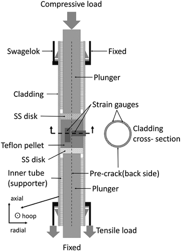
shows a schematic diagram of the biaxial-EDC test apparatus used in this study [Citation14]. A Teflon pellet of 8 mm in diameter and 10 mm in length was placed at the centre of the sample and two stainless-steel disks of 8.15 mm in diameter and 2 mm in thickness were placed at the top and bottom of the Teflon pellet. Both ends of the sample were connected to the tensile jigs by using a pair of Swagelok fittings outside the specimen and a strengthening brass tube inside the specimen. Two plungers which were made of stainless-steel were used to compress the Teflon pellet through the stainless-steel disks. Two strain gauges, with a gauge length of 2 mm and a width of 1.5 mm, were attached to the axial centre on the opposite side of the pre-crack on the outer surface of the sample so that the axial and hoop strains were simultaneously measured. Displacements of the tensile load cell and the EDC compressive load cell were simultaneously controlled based on the real-time strain measurement to maintain a constant ratio of axial to outer surface hoop strains. All tests were performed at room temperature.
Figure 1. Scheme of biaxial-EDC apparatus.
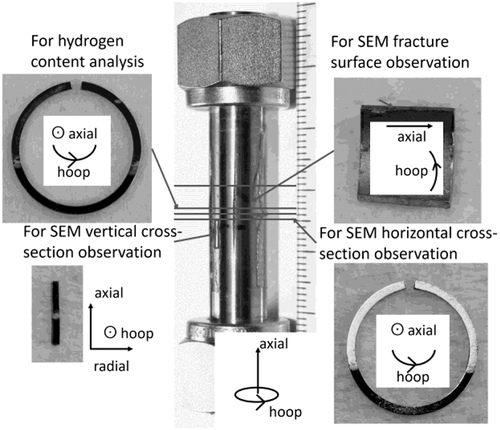
shows a typical appearance of a post-test sample. An opening along the axial direction can be found at the pre-crack location. The central part of the sample, i.e. the part of the cladding tube failed under biaxial stress around the Teflon pellet, was cut into four pieces for hydrogen content analysis, metallography along the vertical (R-Z plane) and horizontal (R-θ plane) cross-sections to confirm hydride morphology in the specimen, and fracture surface observation. The hydrogen content was measured after the biaxial-EDC test by using a LECO RHEN602 Hydrogen Determinator. The sample for metallography was mounted into resin, mirror-polished mechanically and finally polished electro-chemically at a temperature of –20°C and a voltage of 22 V in a solution of 5% perchloric acid and 95% ethanol. A Hitachi miniscope TM3000 with the capability of capturing back-scattered electron (BSE) image was used for hydride morphology and fracture surface observation because Schrire et al. [Citation15] confirmed that the BSE imaging technique is suitable to observe hydride precipitates in stress-relieved Zircaloy-4 cladding. A JEOL JSM7100F equipped with an electron backscatter diffraction system was used to confirm the texture of the stress-relieved Zircaloy-4 cladding used in this study.
Figure 2. Example of post-biaxial-EDC test sample and cutting plan for post-test examinations.
3. Results and discussion
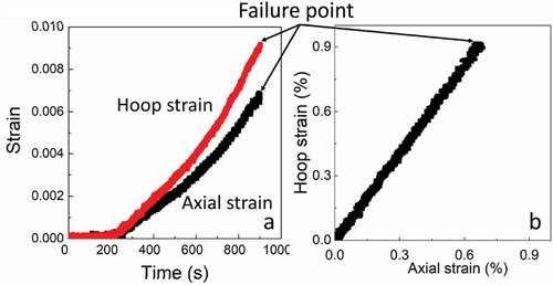
) shows typical time histories of outer surface hoop strain of sample and axial strain in the sample during the biaxial-EDC test, which exhibited a strain rate of the order of 10–5/s. ) shows a strain path history extracted from the time histories, in which the strain ratio was constant throughout the test.
Figure 3. Example of (a) strain-time history and (b) strain path history during biaxial-EDC test. The strain ratio in this example is εz/εθ = 0.75.
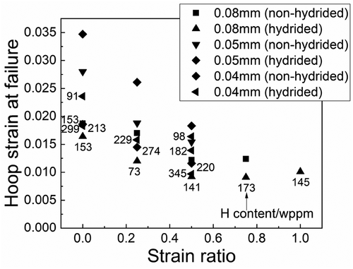
shows the relationship between the failure strains and the ratios of axial strain to outer surface hoop strain (strain ratio) of the samples. In the biaxial-EDC test, failure data under higher axial-to-hoop strain ratio was more difficult to obtain due to the increased possibility of failure in the Swagelok joint prior to the failure of the sample itself caused by the propagation of the pre-crack. Hence, the data series covering a wide range of strain ratio in the figure are solely from samples with pre-crack depth of 0.08 mm, which failed at a smaller hoop strain than other samples: prior to the failure in the joint part. The following tendencies can be noticed in the figure: (1) the failure strain of the hydrided sample is significantly lower than that of the non-hydrided sample, which had the same pre-crack depth and was tested under the same strain-ratio condition. (2) For the samples with the same pre-crack depth, the failure strain significantly decreases as the strain ratio increases from 0 to 0.5 and slightly increases as the strain ratio increases from 0.5 to 1. This dependency on strain ratio is observed in both non-hydrided and hydrided samples, regardless of the variation in hydrogen content (less than ~100 wppm) in hydrided samples. The dependency of failure strain on strain ratio agrees well with the prediction of Shinozaki et al. [Citation13], in which failure strain of a cladding sample with a pre-crack on the outer surface was calculated based on the ductile damage model implemented in ABAQUS software [Citation16,Citation17], fitting the results of the biaxial-EDC test (axial load was applied prior to EDC test, in their case). The failure strain discussed in this study is the outer surface hoop strain at failure, which was measured with strain gauges. However, one should notice that PCMI occurs at the inner surface of the cladding, which suggests that inner-surface strain of cladding should be used to evaluate the effect of the fuel pellet expansion during an RIA condition: the amount of fuel pellet expansion is related to the fuel enthalpy that is a parameter used in regulatory guidelines for RIA [Citation1–Citation5].
Figure 4. Dependency of failure strain on strain ratio (samples #1–#25 in ).
) shows the dependency of failure strain on the crack depth in the case of non-hydrided samples. The failure strain decreases as the pre-crack depth increases under each strain ratio. A similar trend was observed in the simulation results obtained by Udagawa et al. [Citation16] under the plain strain (εz/εθ = 0) loading condition. ) shows the dependency of failure strain on the crack depth in the case of the corresponding hydrided samples. While the dependency of failure strain on the pre-crack depth is similar to the non-hydrided case, the failure strain drop from the corresponding non-hydrided samples becomes larger as the depth of the pre-crack decreases and when the test is performed under a lower strain ratio condition, as pointed out with arrows in ).
Figure 5. Failure strain as a function of crack depth in case of (a) non-hydrided samples and (b) hydrided samples. (c) Decrease in failure strain of hydrided samples compared with corresponding non-hydrided samples as a function of pre-crack depth (samples #1–#3, #5, #7, #9, #11–#19, #21–#23 in ). The arrows in (c) points out the data points showing larger decrease in failure strain of the samples with smaller crack depth and tested under smaller strain ratio.
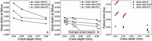
The effect of hydrogen content was then examined in more detail for the samples with pre-crack depth of 0.04 mm with which failure-limit drop was most apparent in ). shows the dependency of failure strain on the hydrogen content in the samples with a pre-crack depth of 0.04 mm under strain ratios of εz/εθ = 0 and 0.5, respectively. The failure strain seems generally to be lower under the condition of εz/εθ = 0.5. The failure strain decreases rapidly at low hydrogen content region and tends to saturate as the hydrogen content increases under the condition of εz/εθ = 0. The failure strain is less sensitive to the increase of hydrogen content in low hydrogen-content region under the condition of εz/εθ = 0.5. The curve is nearly straight and the tendency of saturation is hardly observed in the hydrogen-content region presented in this study. To explain the change in this decreasing tendency from the microscopic viewpoint, the appearance of sample fracture surface and the hydride morphology in the sample were further examined.
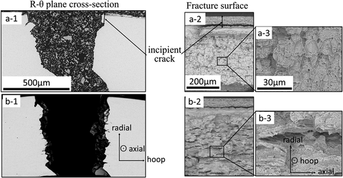
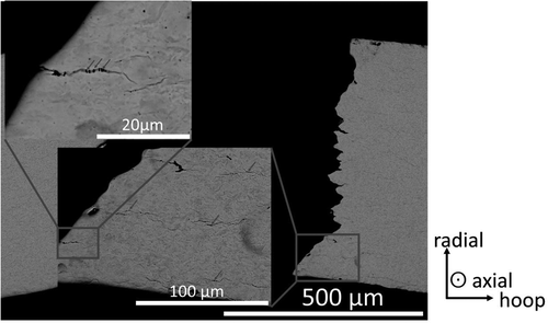
Typical crack propagation patterns observed in non-hydrided and hydrided samples are shown in -) and -), respectively. In the case of the non-hydrided sample, the crack initially propagates along the radial direction and turns towards the shear direction. In the case of the hydrided sample, the crack propagates along the radial direction further compared with the case of the non-hydrided sample. The failure of the non-hydrided sample seems ductile, as shown in -) and -). As shown in -) and -), although failure of the hydrided sample seems ductile as well, the dimple size is smaller than that in the non-hydrided specimen, and some traces of hydride platelets are observed in the fracture surface.
Figure 6. Failure strain as a function of hydrogen content under strain ratios of 0 and 0.5 (samples #1, #3–#6, #8–#10 in , to isolate the effect of hydrogen content).
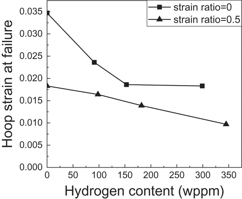
Figure 7. (a-1) Horizontal cross-section, (a-2) fracture surface, and (a-3) its magnification in the case of non-hydrided sample (#19 in ). (b-1) Horizontal cross-section, (b-2) fracture surface, and (b-3) its magnification in the case of hydrided sample (#23 in ).
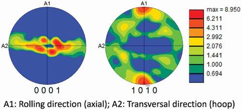
The stress-relieved Zircaloy-4 tube samples used in this study had a texture of (0001) plane in the zirconium matrix, which is parallel to the θ-Z plane in the specimen, as shown in .
Figure 8. Pole figure of a non-hydrided stress-relieved Zircaloy-4 sample used in the present study.
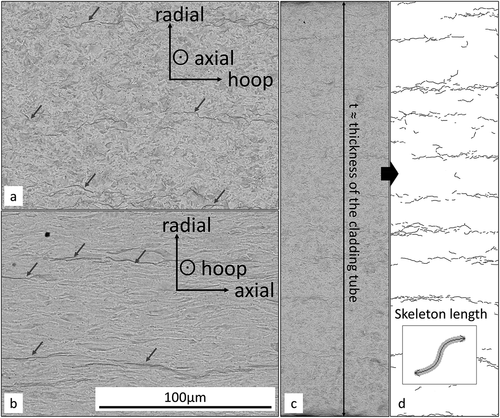
,) show typical BSE micrographs of the horizontal and vertical cross-sections of the samples after electro-polishing process. From these figures, it can be noticed that the hydrides are precipitated as platelets perpendicular to the radial direction. Such relationship between hydride morphology and crystallographic feature of the Zircaloy-4 matrix accords with the results reported by Une et al. [Citation18]. In the biaxial-EDC test, the crack propagated along the radial direction, and the sample deformed under the two principle stresses along the axial and hoop directions. Therefore, the amount and distribution of hydrides precipitated in the horizontal and vertical planes of sample, which are perpendicular to the principle stresses, respectively, and both of which contain the crack propagation direction, were considered important. Here, hydride precipitates appeared as narrow lines on both cross-sections. Therefore, the total length of hydride precipitates in a unit area was set as the basic parameter to evaluate the effect of hydride morphology on the decrease of failure strain. A low magnification suitable for BSE imaging was selected so that all hydride precipitates were visible within the resolution of the scanning electron microscope. A BSE image of the whole wall-thickness of specimen was taken near the failure crack as a representative of the hydride morphology of the specimen, as shown in ). A BSE image was binarised to extract the ‘skeleton’ of the hydride precipitates. ) shows a representative resultant image. In order to express the hydride morphology in specimen, the ‘skeleton length’ (length of the centreline, as shown in the small figure in )) of each hydride mark was measured.
Figure 9. Typical microstructure of electro-polished samples of (a) horizontal cross-section and (b) vertical cross-section. (c) Example of image survey along radial direction on horizontal cross-section, and (d) its resultant image after contrast extraction (sample #16 in ).
Following the hydride morphology evaluation method of Mihara et al. [Citation9], the sums of the ‘skeleton length’ divided by the areas of the resultant images (hydride length per area, HL/A) on the horizontal and vertical (R-Z plane) cross-sections were calculated. Hereafter, these values are noted as HL/A-H and HL/A-V, respectively.
The relationship between the failure strain of sample and the HL/A-H or HL/A-V is discussed with considering the results of samples with a pre-crack depth of 0.04 mm under the strain ratio conditions of εz/εθ = 0 and 0.5, as shown in ,). Here, HL/A-H and HL/A-V have similar amplitudes for each sample. As seen in these figures, the failure strain decreases as the HL/A-H or HL/A-V increases. Under the condition of εz/εθ = 0, while the failure strains change with the HL/A-H or HL/A-V increase in low HL/A-H or HL/A-V region, the failure strains tend to saturate as the HL/A-H or HL/A-V increases. On the contrary, under the condition of εz/εθ = 0.5, while the failure strains are less sensitive to the increase of HL/A-H or HL/A-V, compared with those under the condition of εz/εθ = 0 in low HL/A-H or HL/A-V region, the sensitivity increases as HL/A-H or HL/A-V increases.
Figure 10. Dependency of failure strain of cladding samples on (a) HL/A-H, (b) HL/A-V, and (c) HA/V. (d) Nearly proportional relationship between HA/V and hydrogen content (same samples as those in ).
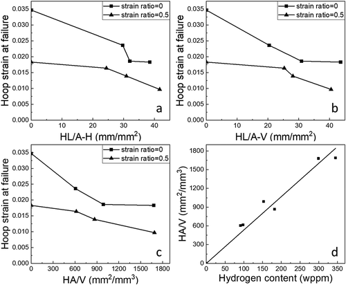
The product of HL/A-H and HL/A-V can be treated as the area of the hydride platelets in a unit volume, hereafter noted as HA/V. ) shows the dependency of failure strain on HA/V. The trend seen in the figure is quite similar to the relationship between failure strain and hydrogen content, which is shown in . In ), nearly proportional relationship can be seen between hydrogen content and HA/V of these samples. This suggests that the hydrogen content in the sample and HA/V of the sample are essentially equivalent factors.
Considering the embrittlement of the fuel cladding from the perspective of hydride morphology, the following scenario may explain the results obtained in this study: because the hydride phase is extremely brittle [Citation19–Citation21], it is likely that upon the deformation of the hydrided cladding tube, micro-cracks will form in the hydride phase due to the fracture of hydrides. Puls [Citation22] observed multiple cracks and voids in one hydride precipitate during a tensile test of hydrided zirconium, in which the hydride platelet was parallel to the tensile direction and the micro-cracks were all perpendicular to the tensile direction. Simpson [Citation23] indicated that some plastic strain might be necessary for the initiation of the fracture of hydrides in zirconium-based alloys, because the critical stress was lower in a softer base-material. From the experimental results presented by Puls [Citation22], Simpson [Citation23], and Shi [Citation24], it is noticed that the fracture of hydride initiates near the yielding point of the base alloy. Therefore, considering the characteristics of the stress/strain conditions in the present study, the micro-cracks forming parallel to the R-θ plane and the R-Z plane of the cladding tube can be expected, and it is likely that the number of micro-cracks increases with increasing the strain level in hoop and axial directions and the values of HL/A-H and HL/A-V. Specifically, in the case of εz/εθ = 0, the micro-cracks in precipitated hydride may appear mainly parallel to the R-Z plane because of zero strain along the axial direction. In the case of εz/εθ = 0.5, micro-cracks may also appear in the R-θ plane owing to the tensile strain along the axial direction. Although traces of the micro-cracks in the region that experienced large plastic deformation could be captured on the horizontal cross-sections of the samples near the failure crack, as shown in , it is considered that most micro-cracks are closed after failure, owing to elastic recovery of the cladding and become difficult to observe after the biaxial EDC test because the samples in this study failed under relatively smaller plastic strains compared with the conditions used in [Citation22]. If there are more micro-cracks near the pre-crack, there will be a higher possibility for the pre-crack to start propagation by linking to the nearby micro-cracks, causing the failure of the samples at a smaller strain level. When εz/εθ = 0, the quantity of the micro-cracks is contributed from HL/A-H, but when εz/εθ = 0.5, the quantity of the micro-cracks is contributed from both HL/A-H and HL/A-V. As a result, decrease of failure limit in respect of hydrogen content increase slowed down under the condition of εz/εθ = 0 compared with that of εz/εθ = 0.5.
Figure 11. Black dots observed in hydride precipitates near failure crack (sample #25 in ).
4. Concluding remarks
The effect of hydride precipitates on the failure strain of pre-cracked cladding tube under biaxial stress conditions was investigated by biaxial-EDC testing method. The obtained failure strain data indicated that the biaxial stress condition affects the sensitivity of failure strain through the condition of hydrides precipitated in the sample. The influence of hydride morphology on the observed sensitivity change was discussed by quantifying the spatial distribution of hydrides in two different manners, i.e. two-dimensional (HL/A-H, HL/A-V) and three-dimensional (HA/V) hydride densities, in the failed sample. The features found in these observations and their analysis results are summarized as follows:
The failure strain of the hydrided sample significantly decreased, compared with that of the non-hydrided sample. The failure strain rapidly decreased as the strain ratio increased from 0 to 0.5 and slightly increased as the strain ratio increased from 0.5 to 1.
The failure strain of the pre-cracked sample significantly decreased as the pre-crack depth increased. The difference in failure strain between the hydrided sample and the non-hydrided sample with the same pre-crack depth was larger when the pre-crack depth was shallower or when the strain ratio was smaller.
The decrease in the failure strain of the sample decelerated as the hydrogen content increased under a strain ratio of εz/εθ = 0, but decreased nearly linearly under a strain ratio of εz/εθ = 0.5. This finding suggests that an axial strain component plays an important role in hydride embrittlement effect under RIA conditions. Based on the comparison among the dependencies of failure strain on HL/A-H, HL/A-V, and HA/V, it is considered that a scenario that assumed the formation and number of micro-cracks in the hydride precipitates in the R-θ and R-Z planes which are dependent on a strain ratio would hold as an elementary cladding failure process to explain such phenomena.
Acknowledgments
The authors would like to thank Dr. Y. Yamaguchi and Mr. S. Kikuchi for their technical assistance.
Disclosure statement
No potential conflict of interest was reported by the authors.
Notes
1. εz: axial strain, εθ: hoop strain.
Related Research Data
References
- U.S. AEC. Regulatory Guide 1.77 - Assumptions used for evaluating a control rod ejection accident for pressurized water reactors. U.S. Atomic Energy Commission - Directorate of Regulatory standards, Regulatory guide 1.77, 1974 May. Washington (DC).
- Macdonald PE, Seiffer SL, Martinson ZR, et al. Assessment of light water reactor fuel damage during a reactivity initiated accident. Paper presented at: CSNI specialist meeting on safety aspects of fuel behavior in off-normal and accident conditions; 1980 Sep 1–4; Espoo, Helsinki, Finland.
- NEA. Nuclear fuel behaviour under reactivity-initiated accident (RIA) conditions. France: Nuclear Energy Agency, OECD; 2010. (Report NEA No. 6847). ISBN 978-92-64-99113-2.
- Desquines J, Koss DA, Motta AT, et al. The issue of stress state during mechanical tests to assess cladding performance during a reactivity-initiated accident (RIA). J Nucl Mater. 2011;412:250–267.
- Fuketa T, Nagase K, Ishijima K, et al. NSRR/RIA experiments with high-burnup PWR fuels. Nucl Saf. 1996;37(4):328–342.
- Fuketa T, Sasajima H, Sugiyama T. Behavior of high-burnup PWR fuels with low-tin zircaloy-4 cladding under reactivity-initiated-accident conditions. Nucl Technol. 2001;133:50–62.
- Udagawa Y, Sugiyama T, Suzuki M, et al. Stress biaxiality in high-burnup PWR fuel cladding under reactivity-initiated accident conditions. J Nucl Sci Technol. 2013;50(6):645–653.
- Fukuda T. Development of pre-cracked cladding specimen for PCMI failure study. Tokai, Japan; 2010 May 19–20. (Fuel Safety Research Meeting 2010).
- Mihara T, Udagawa Y, Sugiyama T, et al. The influence of hydride morphology on the crack propagation through fuel cladding wall. Paper presented at: 2014 international congress on advances in nuclear power plants; 2014 Apr 6–9; Charlotte, NC, USA.
- Nagase F, Fuketa T. Investigation of hydride rim effect on failure of Zircaloy-4 cladding with tube burst test. J Nucl Sci Technol. 2005;42(1):58–65.
- Menibus AH, Auzoux Q, Mongabur P, et al. Fracture of Zircaloy-4 cladding tubes with or without hydride blisters in uniaxial to plane strain conditions with standard and optimized expansion due to compression tests. Mater Sci Eng A. 2014;604:57–66.
- Leroy M, Parrot A, Leclercq S. Failure characteristics of cladding tubes under RIA conditions through electromagnetic forming, Transactions, SMiRT 19. Toronto, Canada; 2007.
- Shinozaki T, Udagawa Y, Mihara T, et al. Improved-EDC tests on the Zircaloy-4 cladding tube with and outer surface pre-crack. J Nucl Sci Technol. 2016;53(9):1426–1434.
- Li F, Mihara T, Udagawa Y, et al. Biaxial-EDC test attempts with pre-cracked Zircaloy-4 cladding tubes. Paper presented at: 25th international conference on nuclear engineering; 2017 May 14–18; Shanghai, China.
- Schrire DI, Pearce JH. Scanning electron microscope techniques for studying Zircaloy corrosion and hydriding. In: Zirconium in the Nuclear Industry: Tenth International Symposium, ASTM STP1245. Philadelphia; 1994. p. 98–115
- Udagawa Y, Mihara T, Sugiyama T, et al. Simulation of the fracture behavior of Zircaloy-4 cladding under reactivity-initiated accident conditions with a damage mechanics model combined with fuel performance codes FEMAXI-7 and RANNS. J Nucl Sci Tech. 2014;51(2):208–219.
- Dassault Systemes Simulia Corp. Abaqus 6.11 analysis user’s manual. Providence, RI: Dassault Systemes Simulia Corp.; 2011. (Chapter 23, Progressive Damage and Failure).
- Une K, Nogita K, Ishimoto S, et al. Crystallography of zirconium hydrides in recrystallized Zircaloy-2 fuel cladding by electron backscatter diffraction. J Nucl Sci Tech. 2004;41(7):731–740.
- Lanzani L, Ruch M. Comments on the stability of Zirconium hydride phases in Zircaloy. J Nucl Mater. 2004;324:165–176.
- Daum RS, Chu YS, Motta AT. Identification and quantification of hydride phases in Zircaloy-4 cladding using synchrotron X-ray diffraction. J Nucl Mater. 2009;392:453–463.
- Barraclough K, Beevers C. Some observations on the deformation characteristics of bulk polycrystalline zirconium hydrides. J Mater Sci. 1969;4:518–525.
- Puls MP. Fracture initiation at hydrides in zirconium. Metall Trans A. 1991;22:2327–2337.
- Simpson LA. Criteria for fracture initiation at hydrides in zirconium-2.5 pct niobium alloy. Metall Trans A. 1981;12:2113–2124.
- Shi SQ, Puls MP. Fracture strength of hydride precipitates in Zr-2.5Nb alloys. J Nucl Mater. 1999;275:312–317.