
 ?Mathematical formulae have been encoded as MathML and are displayed in this HTML version using MathJax in order to improve their display. Uncheck the box to turn MathJax off. This feature requires Javascript. Click on a formula to zoom.
ABSTRACT
FEMAXI-8 is the latest version of the fuel performance code FEMAXI, which has been developed by the Japan Atomic Energy Agency (JAEA) to analyze the thermal and mechanical behavior of a single fuel rod under primarily normal operation conditions and anticipated transient conditions. The development after the release of the previous version FEMAXI-7 addressed modeling on thermal and mechanical effects of fuel pellet relocation, fission gas release, fission-gas-induced swelling, etc., to provide a better description of fuel behavior observed in irradiation tests and underlying phenomena. Another key advance is the introduction of new mechanical calculation options with the intension of producing an improved treatment of various factors that affects stability of calculation, namely, time step control and nonlinear factors such as pellet cracking, contact between axial nodes, and axial friction between fuel pellets and cladding tube. Such factors were a primary source of numerical problems encountered by former versions of FEMAXI and have hindered thorough assessment of their predictive performance. A validation analysis performed against 168 irradiation test cases using a set of consistent calculation models implemented in FEMAXI-8 revealed that the new version makes reasonable predictions in terms of fuel center temperature, fission gas release, rod free volume, and cladding deformation, under steady-state and power ramp conditions.
1. Introduction
The fuel performance code FEMAXI has been developed by the Japan Atomic Energy Agency (JAEA) for the purpose of analyzing fuel behavior under both normal operational and anticipated transient conditions in light water reactors (LWRs) [Citation1–Citation3]. The development of the previous versions FEMAXI-V, FEMAXI-6, and FEMAXI-7 in recent years primarily focused on the extension of code capabilities and options for modeling high-burnup UO2 and mixed oxide (MOX) fuels as a supporting tool for research activities. Although the codes have been delivered as open software and have been utilized widely in many analytical studies, the previous versions lacked extensive validation work in terms of calculations with respect to a wide range of fuel specifications and irradiation conditions with a consistent set of calculation models and comparisons with experimental data.
The development of FEMAXI-8 maintained the modeling efforts on the thermal and mechanical effects of fuel pellet relocation, fission gas release, fission-gas-induced swelling, etc., to provide a better description of fuel behavior observed in irradiation tests and underlying phenomena. In addition, much effort has been also devoted to improving the numerical stability of the code and to constructing/collecting irradiation test database, both of which had been bottlenecks to a systematic validation work. This paper provides descriptions of the key improvements made under FEMAXI-8 based on feedback from critical assessments on the performance of the FEMAXI-7 code, updates and refinements in modelling and database extension after the previous work [Citation4], and a summary of the results of a systematic computational assessment of 168 irradiation test cases performed to validate FEMAXI-8. Finally, we provide a benchmark calculation to validate the improved numerical/computational execution performances of FEMAXI-8, relative to FEMAXI-7.
2. Key updates to FEMAXI-8
FEMAXI-8 maintains the core features of previous versions of FEMAXI as a fuel performance code and, as such, comprises of two main modules – a thermal calculation module and a mechanical calculation module. The thermal module describes phenomena such as heat generation by fission reaction within fuel pellets, heat conduction inside fuel pellets and cladding in radial direction, heat transfer across the pellet/cladding (P/C) gap and fuel rod surface, thermal effects of fuel cracking, fuel densification, fuel swelling, thermal expansion of fuel pellets and cladding, and fission gas migration inside fuel pellets and release to the P/C gap space. The mechanical module describes force equilibrium between fuel pellets and cladding, stress/strain inside fuel pellets and cladding, fuel crack generation, and the mechanical effects of fuel cracking. In this section, we provide descriptions of the key models that have been newly developed or modified for FEMAXI-8 based on feedbacks from critical assessments of the performance of the previous version, FEMAXI-7. We avoid repeating long descriptions of models that are unchanged from FEMAXI-7 [Citation1], focusing instead on important updates that have been made in the latest version. Our previous report [Citation4] addressed many other miscellaneous improvements in flexibilities of mesh configuration and inelastic strain components considered, and models for fuel thermal conductivity and fuel densification etc. Recommended values for model parameters appearing in equations will be provided based on the code validation summarized in Section 3.2.
2.1. Time step control and data transfer between mechanical and thermal calculations
In addition to the similar features implemented in the former versions but activated only during a limited range of events, namely, detection of a high creep rate or a P/C contact during a time step, the mechanical calculation module of FEMAXI-8 supports automatic time step subdivision in the case that it detects a convergence failure for any reason. This feature critically reduces the necessity of manual modification of input parameters to implement time step control, which becomes unaffordable as the number of calculation increases. In addition, the data transfer procedure between the mechanical and thermal calculation modules became more consistent in FEMAXI-8, whereas in the former versions, inconsistency between state variables occasionally resulted in a poor convergence.
2.2. Friction between fuel stack and cladding tube in axial direction
Whereas FEMAXI-7 applied a special normalization by P/C contact surface area to compute mechanical P/C interaction in axial direction [Citation1], the P/C friction model adopted by FEMAXI-8 conforms to the standard Coulomb’s friction law. Namely the frictional force is proportional to the P/C contact force. The friction coefficient is computed using the following formula:
where is the maximum value of the friction coefficient,
is the friction coefficient at the beginning of life (BOL), BD is a state variable (the ‘bonding parameter’) [Citation1] used to represent the progress of chemical P/C bonding formation as burnup proceeds, and
is increment in the friction coefficient per unit increase in BD. The friction coefficient is calculated for each axial nodes.
2.3. Mechanical interactions between axial nodes
The FEMAXI codes generally divide a fuel stack into several axial nodes. The mechanical calculation modules of these codes have adopted a buffer element at the top of a finite element that represents a solid portion of the fuel stack, as shown in . The open circle denotes the degree of freedom in the radial direction while the triangle and the square represent the degree of freedom in the axial direction. The closed symbols denote that there is actually a sole degree of freedom for each symbol, namely, shared between all the finite elements in an axial node. The buffer element is valid for modeling mechanical interactions between two adjacent axial nodes. It can be also used for the straightforward treatment of fuel elements with an uneven configuration of axial lengths as occurs where there are dished or chamfered pellets: this case is illustrated in the figure, in which the three solid elements have different axial lengths. The buffer element behaves softly when the buffer size is large and vice versa. The steep change from soft to hard mechanical response upon shrinkage of the buffer element, however, introduces a strong nonlinearity analogous to that encountered in a solid/solid contact problem, and previous versions required a relatively large buffer size (typically about 1% of node length) to avoid numerical problems. In addition, overlaps between axial degrees of freedom, namely, negative buffer size, were neglected in previous versions, leading to the potential occurrence of another types of numerical problems. FEMAXI-8 continually monitors for such an overlap event and applies gradual hardening to the buffer element each time it detects an overlap. This update has reduced the necessary buffer size for stable calculation to 0.1%, which is lower than the level of fuel thermal expansion under LWR operational conditions.
Figure 1. Configuration of finite elements and nodes representing an axial node of fuel stack.
To model the P/C friction, former versions adopted a procedure in which a single-node finite element method (FEM) calculation was carried out for each axial node to produce an estimate of the frictional force that was fed into a global FEM calculation that was carried out over the entire rod. The procedure sometimes produced unphysical results such as overly large elongation of cladding tube under strong pellet cladding mechanical interaction (PCMI) and appeared to need modifications for more robust behavior. FEMAXI-8 assumes a default no-friction condition on all the axial nodes with closed P/C gaps to perform the global FEM calculation. For nodes where the axial force exceeds the frictional force, the code reduces the axial force gradually and applies it as a modified boundary condition to the FEM calculation in the next iteration. The convergence criteria are met when all of the predicted axial forces are in a range that can be reached by P/C friction, and all of the relationships between predicted axial displacements and frictional forces are consistent.
2.4. Mechanical response of cracked fuel pellets
FEMAXI-8 incorporates an algorithm known as the stress transfer process in its mechanical calculation procedure to properly model the mechanical responses of cracked fuel pellets. The code checks the stress values in the fuel elements during each FEM calculation. Upon detecting a given tensile stress value, imaginary stress components that cancel the tensile stress are applied to the corresponding finite element in the next iteration. These operations enable to suppress the tensile components of stresses in fuel elements below a given level (which under FEMAXI-8 is zero) without altering pellet mechanical properties, which was the sole option under FEMAXI-7. This is an important improvement because such unphysical tensile components undermine the reliability of code predictions not only on mechanical response of fuel pellets but also on fission gas behavior.
This stress component feature also enables the updating of the mechanical contribution component of the relocation model, which expresses the effect of cracks inside a fuel pellet on the mechanical responses of a fuel stack by formulating the effective elastic constants as a function of stress level, focusing particularly physics in fuel pellets or a fuel stack. This relocation model is set to be inactive along the fuel rod axial direction, as it is not possible to discriminate the effect of relocation in the axial direction from the mechanical behavior of the buffer element discussed in Section 2.3, which produces a very similar effect. Young’s modulus along the radial and circumferential direction is calculated using the following formulae:
where [Pa] is the Young’s modulus of a fuel pellet without cracks;
,
, and
are empirical parameters,
is the fuel relocation strain; and
is the initial value of
. The parameter
corresponds to Young’s modulus of a fully cracked fuel pellet. This formulation supports an arbitrary order of dependency on fuel cracking state, whereas the previous version only supported linear or quadratic dependencies on stress, which often resulted in overly hard mechanical responses of a fuel stack despite its cracking state. The updated model takes relocation strain as the primary parameter instead of stress to achieve numerical stability. Still higher-order formulation spurs nonlinearity in the problem and required the supportive improvements described in Sections 2.1 and 2.3. The Poisson effect is not taken into account for
. The relocation
is determined by introducing a temporary strain increment as the initial strain in constructing the stiffness matrix for the FEM solver and then computing
by subtracting all the other independent components, including elastic, thermal, plastic, and creep strains, from total strain following an FEM calculation. FEMAXI-8 assumes that the initial strain introduced as a seed of
recovers at each construction of the stiffness matrix to a level specified by an input parameter, as long as the associated pellet expansion is free from inhibition by PCMI.
illustrates variations in the mechanical behavior of a fuel rod introduced by the new options described above to enable the stress transfer process and the higher-order formulation of fuel elastic constants. In the figure, FEM8 corresponds to the reference model specified in this section and in Section 3.2, which employs all of the updated mechanical calculation features of FEMAXI-8, while FEM7 corresponds to a conventional relocation model that assumes 50% closure of the initial P/C gap. The ‘Remarked node’ in the figure refers to the axial node from which the plotted outputs of P/C contact pressure and fuel axial stress are extracted. The simulated fuel behavior for an identical base irradiation condition [Citation5] exhibit that the case FEM8 with the new options expresses a relatively ‘soft’ mechanical interaction in contrast to the sharp on/offs of PCMI pressure seen under FEM7 with the conventional model ()). Undesirable generation of tensile stress in the axial direction of the fuel rod also becomes moderate under FEM8 ()).
Figure 2. Comparison of mechanical behaviors of the fuel rod irradiated at the DR3 reactor in RISO program [Citation5] simulated with two different relocation model sets FEM7 and FEM8: (a) linear heat rate and P/C contact pressure and (b) fuel axial stresses in the 1st and 2nd finite elements.
![Figure 2. Comparison of mechanical behaviors of the fuel rod irradiated at the DR3 reactor in RISO program [Citation5] simulated with two different relocation model sets FEM7 and FEM8: (a) linear heat rate and P/C contact pressure and (b) fuel axial stresses in the 1st and 2nd finite elements.](/cms/asset/2e575b4a-bba1-4e58-b45b-49d5751a18ae/tnst_a_1595766_f0002_oc.jpg)
2.5. Thermal effects of cracks inside fuel pellets
FEMAXI-8 takes into account more parameters than the previous versions in order to compute the contribution of the thermal effect of P/C gap to the calculated gap conductance, as follows:
where [W/cm] is the linear heat rate,
is a state variable that depends on burnup and temperature,
[cm] is the radial P/C gap width calculated in the mechanical model,
[cm] is the radial P/C gap width for thermal calculation,
[cm] is the initial value of fuel pellet outer diameter, and
are empirical parameters. The state variable BT [K
GWd/tU] is computed at each axial node by
where [GWd/tU] is the average burnup increment over an axial node and
[K] is the center temperature of an axial node.
This formulation attempts to be as flexible as possible in taking into account the gap reduction induced by fuel pellet cracking, known to be a thermal effect of fuel relocation. The parameters were determined through the validation work described in the next section and in [Citation4].
FEMAXI-8 applies an additional feature to capture the physics of fuel cracking that contribute to the eventual effect of relocation on radial heat transfer inside a fuel rod. This is done under the basic assumption that there should be a countereffect of the gap reduction by fuel relocation, namely, that degradation of radial heat transfer should occur inside fuel pellets as a result of cracking, in particular when the normal vectors of the cracks lie in the radial direction of the fuel pellet. The Distribution of Generated Cracks model computes the effective fuel thermal conductivity [W/cm/K] as
where [cm] is the radial width of thermal calculation mesh for a fuel element;
[W/cm/K] is the thermal conductivity of a fuel pellet without cracking;
[cm] is the assumed radial width of cracks in a fuel element;
[cm] is the solid/gas jump distance [Citation1];
[W/cm2/K] is the radiation heat transfer coefficient across a crack;
is the number of thermal meshes where the thermal effect of cracks is taken into account; and
,
,
,
,and
are empirically determined model parameters. The variable
[cm] is the sum of the radial widths of the cracks inside a fuel stack as calculated in the mechanical model, which is assumed to be equivalent to sum of the radial component of relocation strain
. The value
= 3 is currently set in the model, and cracks are introduced in the second, fifth, and eighth radial fuel elements (where the first fuel element corresponds to the innermost one) when the radial mesh number for the thermal calculation is set to 9.
2.6. Transient fission gas migration to fuel grain boundaries
Preliminary calculations performed on various irradiation conditions (see ) [Citation4] by FEMAXI-8 prior to the current update showed that the code tends to underestimate transient fission gas release under ramp test conditions as far as it counts solely thermal diffusion of fission gas atoms as a release path to the grain boundary with diffusion coefficients whose magnitude lies in the range supported by experimental data. Although different mechanisms to explain additional release at such transient conditions have been discussed [Citation6,Citation7], it has been difficult to determine which is the most promising. FEMAXI-8 has adopted the biased migration mechanism to formulate the additional fission gas release to the grain boundary, while another formulation was also implemented and validated [Citation4]. The model uses the value of intragranular gas bubble porosity as an indirect measure for detecting the occurrence of a non-equilibrium fission gas bubble condition with a goal of restricting activation of the model to transient conditions with minimum calculation cost. The fractional release rate of intragranular gas bubbles to the grain boundary, [1/s], is calculated as follows:
Table 1. Summary of irradiation test conditions treated in the validation of FEMAXI-8 [Citation4]
where [m] is the fuel grain size,
is the intragranular gas bubble porosity,
[J/K] is the Boltzman constant,
[K] is the temperature of the fuel element,
[m2/s] is the bubble mobility,
[m3] is the volume of an intragranular gas bubble,
[m3] is the atomic volume,
[K/m] is the temperature gradient in the fuel stack radial direction,
and
represent the contributions of biased migration driven by the gradients of stress and temperature, respectively,
is the critical porosity level at which biased migration is activated, and
are empirical parameters. The parameters
,
,
, and
are currently fixed at 100 MPa, 1012 MPa/m, 150 GPa, and 100 kcal/mol, respectively; the contribution of the
term is minor, whereas the former three parameters could be calculated in the mechanical model. The value of
, which dominates the release rate in the current formulation, is consistent with that adopted previously in Griesmeyer et al. [Citation6]. Another dominant factor
is according to Maiya’s equation [Citation8]. The criterion of model activation
is empirical and determined through the validation work described in [Citation4].
2.7. Fission gas behavior in grain boundaries
FEMAXI-8 has adopted an updated model to treat fission gas behavior in fuel grain boundaries based on a more detailed description of gas bubble states than was originally proposed by Matthews and White [Citation9,Citation10]. This section focuses on the differences made from the original models; a full description of the equations involved is given in [Citation4].
From a numerical viewpoint, the update introduces several independent state variables whose time evolution is computed using rate equations. These include gas bubble porosity and gas inventory
at the grain edge, which are computed separately from the corresponding parameters at the grain face
and
, the projection area of a gas bubble on grain face
, and the bubble length on the grain face
. The model uses the backward differentiation formula scheme, which is implemented in ODEPACK [Citation11], to perform time integration of the rate equations for the variables
,
,
, and
[Citation4,Citation9]. The remaining variables
and
, which were conceived by White, have much rougher time intervals for their time integration [Citation10]. The present model discriminates the gas inventories
and
based on their respective linkage statuses, whereas the original model discriminated them simply by their locations [Citation4]; the face bubble gas inventory already linked to edge bubbles belongs to
rather than to
, and the edge bubble gas inventory in already linked to the rod free volume is counted as the portion released to the rod free volume.
The model computes the linkage fraction of face bubbles to edge bubbles as an increasing function of ; this formulation represents something of a hybrid of the two preceding models [Citation9,Citation10]. Relative to the Matthews’ model, incorporation of
as a parameter of linkage fraction likely has an effect of accelerating gas migration from the grain face and through the grain edge to the rod free volume under a fast transient, under which decreasing rate of
owing to bubble shrinkage becomes less significant.
The fraction of gas atoms in that contributes to the pressure of face gas bubbles,
, has a more flexible form than the original model (which had a burnup dependency):
where are empirical parameters used to add flexibility to the formulation.
Finally, the model adds the computed face bubble and edge bubble porosities and passes the sum to the mechanical calculation module, which uses the porosity calculated in the fission gas model as the component of gas-induced fuel pellet swelling that constitutes a part of the initial strain increment in constructing the stiffness matrix.
3. Validation analysis
To validate the FEMAXI-8 model, the authors prepared an irradiation test database under the cooperation of JAEA and the Secretariat of Nuclear Regulation Authority (SNRA). The validation work comprised comparisons between calculation results and measurements taken from 168 irradiation test cases, feedback of the comparison results to the model parameters, and assessment of the resulting code performance.
3.1. Test matrix
The validation work was to a large extent preceded by the selection of irradiation test cases from a previous thorough assessment on the FRAPCON-4.0 code [Citation12] found in publication. summarizes the conditions of 168 different irradiation tests treated herein [Citation4]. They include an additional 24 test cases containing 12 fuel rods filled with Xe gas to support the thermal contribution component of the relocation model, of which formulation is more complex than that adopted in the preceding FRAPCON work [Citation12]. These additional cases belong to the groups ‘PCT/BOL’ and ‘PCT/LowBU’ identified in . The group ‘Oxidation’ comprising 24 fuel rods with PIE data from JAEA’s research projects involving the Nuclear Safety Research Reactor (NSRR) [Citation13] was added to the validation database after the authors’ previous work [Citation4] to verify the models for cladding waterside corrosion.
Table 2. Groups of validation-calculation cases [Citation4]
3.2. Determination of model parameters
The validation primarily focused on improving the code predictions concerning fuel center temperature and fission gas release (). As the first step, we selected a fuel thermal conductivity model out of the set of models implemented in the code and then tuned the relocation model parameters through analyses of the ‘PCT/BOL’ and ‘PCT/LowBU’ groups. As the second step, we further tuned the relocation model parameters related to burnup dependency along with those of the fuel densification model through analyses of the ‘PCT/LowBU’ and ‘PCT/UO2’ groups. We then analyzed the ‘PCT/MOX’ and ‘PCT/Gd’ groups to confirm the validity of the obtained model parameters for MOX and Gd-doped rods. Fuel temperature was the sole target of optimization in these exercises. The consistent set of model parameters was mainly the relocation model parameters, since the models for fuel thermal conductivity and densification are based on independent experimental data for themselves. The final step of the validation process targeted the optimization of fission gas release and cladding deformation based on analyses of the remaining groups (see ) using the parameters determined in the preceding steps as fixed parameters.
The calculation conditions that we ultimately reached in this validation process follow the interim model parameter set given in [Citation4] with the exception of the updates described in this paragraph. The radial mesh number for a fuel stack is 3 for the mechanical calculation and 9 for the thermal calculation. The radial mesh numbers are 2 for cladding metallic layer, 1 for cladding oxide layer, 1 for P/C gap, and 1 for coolant channel, for both the thermal and mechanical calculations. More precise divisions of up to 36 for a fuel stack and 8 for cladding are available, but the selection of mesh configuration used here was intended to minimize calculation cost as far as the influence of mesh coarsening is acceptable. A mesh number of 9 was chosen after we confirmed that this value provided visible but minor differences in results from those obtained at a mesh number of 6. The fuel rod was also divided along the axial direction into a maximum of 40 nodes to accurately treat irradiation conditions with significant axial power profiles. To model intragranular fission gas behavior, the present work adopted the new formulation discussed in Section 2.6, and was modified to
to tune the temperature dependency of the activation condition for the model. To model fission gas behavior at the grain boundaries,
,
, and
were modified to 3, 0.05, and 30, respectively.
3.3. Comparisons with experimental data
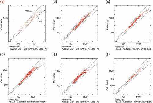
compares the calculated and measured fuel center temperatures. A comparison could be made at any time point for a given test case, because the measured fuel temperatures were online-measured data; as a result, many data points appear on the plots. The majority of the calculated fuel center temperatures lie within the 10% error range. The calibration framework differs from the preceding FRAPCON work [Citation12] in that in the FEMAXI-8 modeling the Ohira’s model for the thermal conductivity of UO2 fuel is used in its original form, the fuel densification rate strongly depends on fuel grain size, and the relocation model treats the effect of fuel internal cracks [Citation14]. The variant of Ohira’s model for MOX and Gd-doped rods [Citation15], herein adopted, needed no additional tuning.
Figure 3. Comparison of fuel center temperatures between calculation results and measurements: (a) ‘PCT/BOL’ group, (b) 0–0.2 GWd/tU of ‘PCT/LowBU’ group, (c) 0.2–5.0 GWd/tU of ‘PCT/LowBU’ group, (d) ‘PCT/UO2’ group, (e) ‘PCT/MOX’ group, and (f) ‘PCT/Gd’ group.
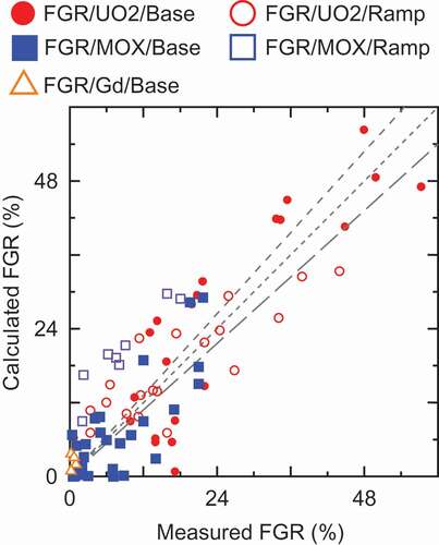
compares the calculated and measured values of fission gas release. The calculation results appear well correlated with the measured fission gas release data. Although there is an obvious overestimation in the ‘FGR/MOX/Ramp’ group, this is difficult to improve as far as one tries to avoid further underestimation in the ‘FGR/UO2/Ramp’ group. At present, the models related to fission gas behavior are common for the UO2 and the MOX cases, whereas the test matrix contains various types of MOX fuels as MIMAS, SBR, etc. It implies that such an extensive survey is highlighting differences in fission gas behavior intrinsic to fuel types. It should be noted, however, that the ‘FGR/MOX/Ramp’ group solely comprised one series of irradiation tests. Thus, the future development should pursue both extension of the test matrix and mechanistic treatment of the elementary processes related to the fission gas behavior to reduce the discrepancy seen in the figures through a proper interpretation. For the same reason, the present work avoided active tuning on the ‘FGR/Gd/Base’ group even though it apparently overestimates fission gas release from the Gd-doped UO2 rods.
Figure 4. Comparison of fission gas releases between calculation results and measurements. In the case of a ramp irradiation test conducted after a base irradiation on the tested fuel rod, fission gas release during the base irradiation is excluded and solely the incremental fission gas release during the ramp irradiation is referred to.
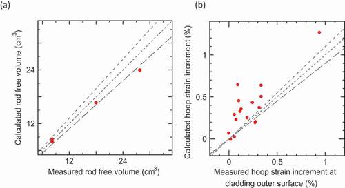
,) shows that the calculation slightly underestimates the rod-free volume while overestimating cladding deformation induced by power ramps to some degree. The current model parameters are intended for more mitigating suppressing effect of hydrostatic pressure in fuel matrix on fission gas release than that on gas-induced fuel swelling. Although such uneven tuning might appear less self-consistent, the code otherwise would produce more underestimation of fission gas release or overestimation of cladding deformation. Matthews also noted uneven suppressing effects on fission gas release and on fuel swelling in their analysis on separate experimental data.
Figure 5. Comparison of (a) rod free volume after base-irradiation and (b) cladding deformation induced by a power ramp between calculation results and measurements: (a) ‘FreeVol’ group and (b) ‘HoopStrain’ group, respectively.
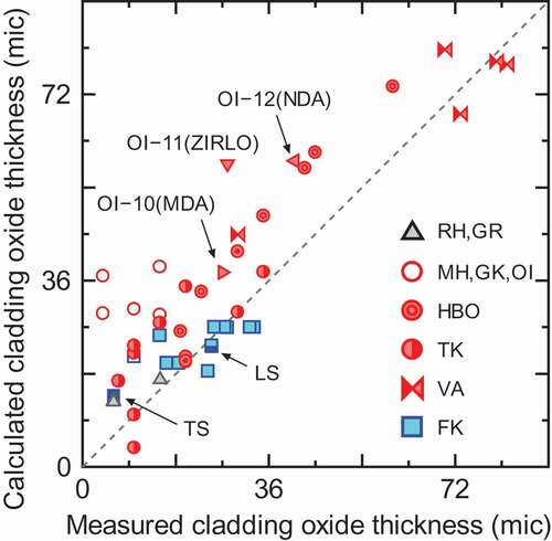
shows that the calculation generally overestimates cladding oxide thickness when the following models are applied without additional tuning. FMAXI-8 adopts the corrosion models for Zircaloy-4 and M5TM for pressurized water reactors (PWRs) and Zircaloy-2 for boiling water reactors developed in the preceding FRAPCON work [Citation12]. The Zircaloy-4 model is applied to ZIRLOTM, MDATM, and NDATM with a scaling factor 0.7 on the corrosion rate, low-tin Zircaloy-4 with a scaling factor 0.775, and M-MDATM(SR) with a scaling factor 0.49. In the figure, the labels in the legend show the test IDs used in the NSRR research project and so represent different types of fuel rods with various cladding materials: ‘RH,GR’ for M5TM, ‘MH,GK,OI’ and ‘HBO’ for Zircaloy-4, ‘TK’ for low-tin Zircaloy-4, ‘VA’ for ZIRLOTM, MDATM, and M-MDATM(SR), and ‘FK’, ‘TS’, and ‘LS’ for Zircaloy-2. The dependency of overestimation appears be systematic in the fuel groups irradiated in Japanese PWR plants (HBO, TK, MH, GK, and OI) and prominent in the fuel groups MH, GK, and OI for which conventional Zircaloy-4 cladding is used.
Figure 6. Comparison of cladding oxide thickness after base irradiation between calculation results and measurements for ‘oxidation’ group. Data points are identified with test IDs defined in the NSRR experiment program.
4. Benchmark of execution performance
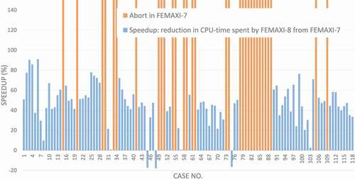
The authors conducted a benchmark analysis comparing the execution performance of FEMAXI-8 to that of FEMAXI-7, by utilizing the irradiation test database treated in the validation work. The benchmark matrix excluded the ‘PCT/BOL’ and ‘PCT/LowBU’ groups (see ), which treat only the initial stage of irradiation, leaving a residual 118 calculation cases. The calculation conditions adopted for the benchmark were completely different from those applied in the previous section, as they contained many options unavailable in FEMAXI-7; in the benchmarking, the calculation conditions were common between the two versions of FEMAXI with the exception of the options to improve numerical stability added under FEMAXI-8 (see Section 2). It should be also noted that the number of radial mesh for the mechanical calculation is 18 for a fuel stack, 2 for cladding oxide layer, and 8 for a cladding metallic layer. The number 18 was the minimum value out of those available both in FEMAXI-7 and in FEMAXI-8, which made the computational cost for the mechanical calculation dominant. Executables built through -O2 optimizations of gfortran-4.7 compiler were run on a Linux machine with an Intel® Core™ i7-7700HQ CPU. shows the benchmark results in the form of the speedups observed in FEMAXI-8 relative to FEMAXI-7; these were approximately 50% speedup on average despite the more rigorous sanity checks applied in FEMAXI-8. Computation time was on the order of hundreds of seconds at maximum. The similarities in speedups between different cases imply that miscellaneous tuning efforts whose effects should be less case-dependent contribute to the improvement. The improvement in numerical stability under FEMAXI-8 is also clear also from its completion of the 32 cases that resulted in abort under FEMAXI-7; by contrast, no aborts were encountered by FEMAXI-8.
Figure 7. Benchmark result on computation speeds of FEMAXI-8 and FEMAXI-7 with 118 calculation cases out of the irradiation test cases treated in the validation of FEMAXI-8 Y.
5. Conclusion
JAEA has developed FEMAXI-8 code, the latest version of the fuel performance code FEMAXI, with improved models, strengthened numerical stability, and execution performance. Associated validation work against 168 irradiation test cases produced a set of recommended model parameters that reproduces the average fuel behavior observed in the validation database. The results of the validation work also highlight the necessity of further extension of the database and models to address intrinsic differences between fuel types and better treat the effects of hydrostatic pressure in suppressing the growth of fission gas bubbles. The models and the parameter sets produced in this work are expected to serve as a foothold toward the application of the FEMAXI code to activities related to safety evaluation pursued by the technical support organizations and regulatory authorities such as SNRA and as a reliable basis for fuel design. It should also be noted that many efforts have been made for modernizing of the code structure from the legacy coding in Fortran-77, performance tuning, and bug fixes. Benchmark calculations performed on 118 irradiation tests to compare FEMAXI-8 and FEMAXI-7 revealed that the new code achieves an approximately 50% speedup and much improved numerical stability. As such, the latest version should strengthen a basis for other recent activities using FEMAXI variants, including accident analyses of conventional LWR fuels, applications involving fast breeder reactor fuels, and studies on innovative fuel/reactor designs known as accident-tolerant fuels and accelerator-driven systems. The initial release of FEMAXI-8 is planned for the first quarter of 2019 and will be available on the website of PRODAS (url:http://prodas.jaea.go.jp).
Acknowledgments
The authors are indebted to A. Yamauchi and K. Kitano for their contribution to the construction of the fuel database utilized for the present validation analysis, and to M. Suzuki and H. Saito for their long-term efforts in the development of the former versions of FEMAXI. A part of the postirradiation examinations analyzed in this study was performed under the research entrusted by Secretariat of Nuclear Regulation Authority.
Disclosure statement
No potential conflict of interest was reported by the authors.
Related Research Data
References
- Suzuki M, Saito H, Udagawa Y, et al. Light water reactor fuel analysis code FEMAXI-7; model and structure. Japan: Japan Atomic Energy Agency; 2013. JAEA-Data/Code 2013-014.
- Suzuki M, Saito H. Light water reactor fuel analysis code FEMAXI-6 (Ver.1)—detailed structure and user’s manual. Japan: Japan Atomic Energy Agency; 2005. JAEA-Data/Code 2005-003.
- Suzuki M. Light water reactor fuel analysis code FEMAXI-V (Ver.1). Japan: Japan Atomic Energy Research Institute; 2000. JAERI-Data/Code 2000-030.
- Udagawa Y, Yamauchi A, Kitano K, et al. Development of fuel performance code FEMAXI-8—model improvements for light water reactor fuel analysis and systematic validation. Japan: Japan Atomic Energy Agency; 2018. JAEA- Data/Code 2018-016. in Japanese.
- Bagger C, Carlson H, Knudson P. Details of design irradiation and fission gas release for the Danish UO2-Zr irradiation test 022. Denmark: Risø National Laboratory; 1978. RISO-M-2152.
- Griesmeyer JM, Ghoniem NM, Okrent D. A dynamic intragranular fission gas behavior model. Nucl Eng Design. 1979 Aug;55:69–95.
- Evans JH. The role of directed bubble diffusion to grain boundaries in post-irradiation fission gas release from UO2: a quantitative assessment. J Nucl Mater. 1996 Jul;238:175–182.
- Maiya PS. Surface diffusion, surface free energy, and grain-boundary free energy of uranium dioxide. J Nucl Mater. 1971 Jan;40:57–65.
- Matthews JR, Wood MH. A simple operational gas release and swelling model: II. Grain boundary gas. J Nucl Mater. 1980 Mar;91:241–256.
- White RJ. The development of grain-face porosity in irradiated oxide fuel. J Nucl Mater. 2004;325:61–77.
- Hindmarsh AC. Odepack a systematized collection of ode solvers. USA: Lawrence Livermore National Laboratory; 1983. ( UCRL-88007).
- Geelhood KJ, Luscher WG. FRAPCON-4.0: integral assessment. Vol. 2. USA: Pacific Northwest National Laboratory; 2015. PNNL-19418.
- Amaya M, Udagawa Y, Narukawa T, et al. Behavior of high burnup advanced fuels for LWR during design-basis accidents. Proceeding Top Fuel 2015; 2015 Sep 13–17;Zurich (Switzerland).
- Ohira K, Itagaki N Thermal conductivity measurements of high burnup UO2 pellet and a benchmark calculation of fuel center temperature. Proceeding ANS Topical Meeting on Light Water Reactor Fuel Performance; 1997 Mar 2–6; Portland (USA).
- Kamimura J, Ide H, Ohira K, et al. Thermal and mechanical behavior modeling for high burnup fuel. Proceeding 2008 Water Reactor Fuel Performance Meeting; 2008 Oct 19–23; Seoul (Korea).