
 ?Mathematical formulae have been encoded as MathML and are displayed in this HTML version using MathJax in order to improve their display. Uncheck the box to turn MathJax off. This feature requires Javascript. Click on a formula to zoom.
ABSTRACT
To evaluate the oxidation behavior of high-burnup advanced fuel cladding tubes in high-temperature steam, laboratory-scale isothermal oxidation tests were conducted using the following advanced fuel cladding tubes with burnups of up to 85 GWd/t: M-MDATM, low-tin ZIRLOTM, M5®, and Zircaloy-2 (LK3). These oxidation tests were performed in steam-flowing conditions at temperatures ranging from 1173 to 1473 K for durations between 120 and 4000 s, and the oxidation kinetics was evaluated. The oxidation kinetics of the high-burnup advanced fuel cladding tube specimens estimated by assuming the parabolic rate law was comparable to or slower than that of the unirradiated Zircaloy-4 cladding tube specimens reported in a previous study. It is considered that the protective effect of the corrosion layer hindered oxidation. Furthermore, no increase in the oxidation kinetics because of the pre-hydriding was observed. The onset times of the breakaway oxidations of these cladding tube specimens were comparable to those of the unirradiated Zircaloy-4 cladding tubes reported in previous studies. Therefore, it is considered that the burnup extension up to 85 GWd/t and the use of the advanced fuel cladding tubes do not significantly increase the oxidation kinetics and do not significantly reduce the onset time of the breakaway oxidation.
1. Introduction
In the safety analysis of a postulated loss-of-coolant accident (LOCA) for a light water reactor (LWR), fuel cladding tubes are exposed to steam at high temperatures until the emergency core cooling system (ECCS) quenches the fuel bundle [Citation1,Citation2]. The fuel cladding tubes may fracture because of the thermal shock caused by quenching when they are oxidized and embrittled significantly [Citation3]. Therefore, the oxidation conditions are restricted by the ECCS acceptance criteria for LWRs to avoid excessive embrittlement of the fuel cladding tubes, which will result in loss of coolable geometry of the reactor core during the LOCA. As per the ECCS acceptance criteria in Japan, the peak cladding temperature shall not exceed 1473 K (1200°C) and the amount of oxidation shall not exceed 15% of the cladding thickness (ECR: equivalent cladding reacted) [Citation4,Citation5].
Because the ECCS acceptance criteria are based on the oxidation conditions, it is necessary to precisely evaluate the oxidation kinetics of the fuel cladding tubes in high-temperature steam. In the 1970s and 1980s, the oxidation behavior, including oxidation kinetics, was extensively evaluated mostly for unirradiated Zircaloy [Citation6–Citation11]. Some of these studies have been referred to in the aforementioned ECCS acceptance criteria. For example, in Japan, the Baker–Just equation [Citation6] has to be used for evaluating the amount of oxidation of the fuel cladding tube while conducting a safety analysis of the postulated LOCA. This can be attributed to the conservative oxidation kinetics that is provided by the Baker–Just equation.
Since the establishment of the ECCS acceptance criteria, the environment surrounding the fuel has changed. This change has been mainly caused by the fuel-burnup extension. In domestic and international application of nuclear power, an increase in fuel burnup has been sought for improving the economic efficiency and for reducing the amount of spent fuel generation. In Japan, the maximum assembly burnup reached a value of 55 GWd/t. The corresponding local (pellet) burnup is conservatively estimated to be approximately 71 GWd/t in a pressurized water reactor (PWR) and is estimated to be approximately 75 GWd/t in a boiling water reactor (BWR) [Citation12]. Because of fuel-burnup extension, the amounts of corrosion, hydrogen absorption, and irradiation damage are observed to increase in the fuel cladding tube. Therefore, it is necessary to investigate the effect of burnup extension on oxidation kinetics. In response to the deterioration of the cladding tube performance that can be attributed to fuel-burnup extension, advanced fuel cladding tubes with a high corrosion resistance and a low hydrogen absorption have been developed [Citation13–Citation15]. Therefore, it is important to evaluate the oxidation kinetics of these advanced fuel cladding tubes.
Several studies have reported on the oxidation kinetics of the advanced fuel cladding tubes [Citation3,Citation16]. However, sufficient evaluation of the oxidation kinetics of the high-burnup advanced fuel cladding tubes has not been conducted yet. The oxidation kinetics of high-burnup advanced fuel cladding tubes in high-temperature steam was reported by Chuto et al. [Citation17]. However, the data of oxidation kinetics were limited to the ZIRLO and M5 cladding tubes, and their burnup range was limited to 66–79 GWd/t. In addition, with respect to the phenomenon of rapid increase in oxidation kinetics, which is referred to as breakaway oxidation [Citation10,Citation18–Citation21], sufficient data and knowledge related to the high-burnup advanced fuel cladding tubes have not been obtained.
This study intends to evaluate the oxidation kinetics and breakaway oxidation behavior of high-burnup advanced fuel cladding tubes. Therefore, laboratory-scale isothermal oxidation tests were performed using the following advanced fuel cladding tubes with burnups of 80–85 GWd/t: M-MDATM, low-tin ZIRLOTM, M5®, and Zircaloy-2 (LK3). These oxidation tests were performed at the Reactor Fuel Examination Facility (RFEF) of the Japan Atomic Energy Agency (JAEA).
2. Experimental procedures
2.1. Specimen preparation
presents a list of the high-burnup advanced fuel cladding tube specimens that were provided for performing the oxidation tests. The specimens were obtained from three PWR fuel rods and a BWR fuel rod that had been irradiated up to a value of 85 GWd/t (local burnup) at the power plants in Europe. The cladding materials were stress-relieved M-MDA, low-tin ZIRLO, M5, and Zircaloy-2 (LK3). summarizes the chemical compositions of these cladding materials. M-MDA is a zirconium alloy having a slightly modified chemical composition from the Mitsubishi-developed alloy named MDA [Citation15,Citation22]. Low-tin ZIRLO is a low-tin version of the ZIRLO alloy, containing an approximate tin content of 0.6–0.8 wt%. M5 is a zirconium alloy with approximately 1 wt% niobium [Citation13]. LK3 is a Zricaloy-2 type alloy; however, the chemical composition, as well as size distribution of the secondary phase particle, is optimized within the composition range of Zircaloy-2 [Citation14].
Table 1. Specimens used in the oxidation tests
Table 2. Chemical compositions of the cladding materials
The thickness of the corrosion layer and the initial hydrogen concentration presented in were measured for reference specimens using image analyses of microstructures and the hot vacuum extraction method with two-step heating exhibiting a precision of 0.08 weight parts per million (wtppm), respectively. Here, the thickness of the corrosion layer was measured on the outer surface of the specimens; the means of results from measurements conducted at four circumferential locations of 0°, 90°, 180°, and 270° are presented. The initial hydrogen concentration is the concentration of hydrogen that is absorbed by the metallic part of the cladding tube specimens during the normal operation of the reactors. The hydrogen analyses were performed using rings of approximately 1.0 mm in length. These reference specimens were sampled from the same fuel rods as the specimens subjected to the oxidation tests.
The specimens subjected to the oxidation tests were prepared as follows. First, short segments were cut from the mother rods. Second, these segments were defueled by drilling. Further, 8.5-mm-long specimens were cut from the defueled segments. Finally, the inner surface of the specimens was ground to completely remove both the fuel pellet and the pellet–cladding bonding layer. The segments were defueld and ground because this study intends to investigate the effect of corrosion and hydrogen absorption on oxidation behavior and not the effect of the fuel pellet or pellet–cladding bonding layer. For the high-burnup Zircaloy-2 (LK3) cladding tube specimens, Zr-liner was also eliminated by grinding to avoid effects of the Zr-liner on oxidation and hydriding behavior during the oxidation tests. After cleaning using acetone, the size and weight of the specimens were measured: image analyses were used to measure the outer and inner diameters; a dial gauge with a precision of 10 m was used to measure the height of the specimens, and a direct reading balance with a precision of 0.01 mg was used to measure the weight of the specimens.
Two types of unirradiated specimens were also provided for the oxidation tests as reference: as-fabricated, stress-relieved M-MDA and as-fabricated low-tin ZIRLO.
2.2. Apparatus and test procedure
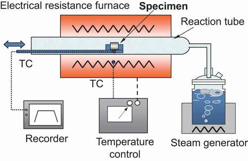
A schematic of the oxidation test apparatus is depicted in . Both the test apparatus and the test procedure of this study are basically the same as those used in our previous study [Citation17]. The test apparatus comprised an electric resistance furnace, a high-purity alumina reaction tube with an inner diameter of 35 mm, and a steam generator. The procedure of each oxidation test can be given as follows. First, both the furnace and the reaction tube were stabilized at a desired temperature. Further, a specimen that was present on a quartz boat was inserted into the midpoint of the reaction tube and was oxidized at atmospheric pressure in a steam-flowing condition. During each oxidation test, the steam flow rate per unit cross-sectional area of the reaction tube was maintained at approximately 3.1 mg cm−2s−1. This flow rate was sufficient for avoiding the steam-starved condition and for oxidizing the entire surface of the specimens [Citation8,Citation10,Citation25]. After each specimen was oxidized for a pre-determined duration, the specimen was pulled out quickly from the reaction tube and was cooled to room temperature. The temperature of the specimen holder was measured using an R-type thermocouple. Furthermore, the temperature of the specimen was estimated using the measured temperature of the specimen holder and the temperature difference between the holder and the specimen, which was measured using a preliminary test.
Figure 1. Schematic of the apparatus for the oxidation test.
presents the conditions under which the oxidation tests were performed. Isothermal oxidation tests were performed at temperatures ranging from 1173 to 1473 K for durations between 120 and 4000 s. depicts the typical histories of the temperatures of the specimen holder during oxidation tests at 1473 K for durations of 120 and 600 s. This figure depicts that the temperatures remained stable during isothermal oxidation for each oxidation test. As depicted in this figure, the heating rate was reduced as the temperature of the specimen holder approached the target temperature. Therefore, the onset time of isothermal oxidation was defined as when the temperature corresponded to 98% of the target temperature. The durations to reach the target temperatures were approximately 170, 120, 140, 100, and 100 s for the oxidation tests at 1173, 1273, 1323, 1373, and 1473 K, respectively. During each isothermal oxidation, the variation of the specimen temperature was estimated to be within approximately 12 K.
Table 3. Conditions of the oxidation tests
Figure 2. Typical histories of the temperatures of the specimen holder during oxidation tests at 1473 K for durations of 120 and 600 s.
After the oxidation tests, the weight of each specimen was measured using a direct reading balance with a precision of 0.01 mg. Further, the weight gain per unit surface area was calculated for each specimen. In addition, for each specimen, the microstructure observation of the transverse cross section, and the measurements of the oxide layer thickness and the hydrogen concentration in the metallic part of the specimens were performed. Here, the thickness of the oxide layer that was formed during the oxidation tests (denoted as ‘HT oxide’) was measured at four circumferential locations of 0°, 90°, 180°, and 270° using image analyses of the microstructures. Further, the hydrogen concentration was measured on a ring of approximately 1.0–1.5 mm in length using hot vacuum extraction method with two-step heating exhibiting a precision of 0.08 wtppm.
3. Results
3.1. Visual observations
Metallographs of the transverse cross-sections of the high-burnup M-MDA cladding tube specimens after performing the oxidation tests are depicted in . The corrosion layer that had been formed during the normal operation was observed at the outer surface for all the examined specimens, as depicted in . Beneath the corrosion layer, HT oxide was observed except in case of low temperature (1373 K) and short duration (120–300 s). Because the corrosion layer in the inner surface was completely eliminated in this study, the corrosion layer was not observed; however, the HT oxide was observed at the inner surfaces of all the examined specimens. Beneath the HT oxide at both the inner and the outer surfaces, both the oxygen stabilized
layer, i.e.
-Zr(O) [Citation1], and the transformed
layer, i.e. prior-
layer [Citation1], were observed for all the examined specimens, as depicted in .
Figure 3. Metallographs of the transverse cross-sections of the high-burnup M-MDA cladding tube specimens after being oxidized at 1173 K for 120 s and 1473 K for 900 s (as etched).
3.2. Weight gain
The weight gains of the advanced fuel cladding tube specimens after being oxidized are depicted in as a function of the square root of oxidation time. For Zircaloy-2 (LK3), the weight gains of unirradiated Zircaloy-4 cladding tube specimens reported by Nagase et al. [Citation26] are shown as reference. For unirradiated M5, weight gains reported by Chuto et al. [Citation17] are shown as reference. In the figure, the lines are obtained after line-fitting using the ordinary least squares regression, and the 95% confidence intervals for these fitted lines are denoted by the shaded regions. The standard errors of the weight gains were estimated to be less than 1%. As depicted in this figure, the weight gains at a temperature of 1473 K were observed to be almost the same between the high-burnup advanced fuel cladding tube specimens and the unirradiated advanced fuel cladding tube specimens. However, at temperatures equal to or lower than 1373 K, the weight gains of the high-burnup advanced fuel cladding tube specimens were slightly smaller than those of the unirradiated advanced fuel cladding tube specimens. A linear relation was observed between the weight gain and the square root of oxidation time, except for both the high-burnup and the unirradiated low-tin ZIRLO cladding tube specimens that were oxidized at a temperature of 1273 K and for the high-burnup Zircaloy-2 (LK3) cladding tube specimens that were oxidized at temperatures equal to or lower than 1373 K.
Figure 4. Weight gains of the advanced fuel cladding tube specimens after being oxidized as a function of the square root of oxidation time. For Zircaloy-2 (LK3), weight gains of the unirradiated Zircaloy-4 cladding tube specimens reported by Nagase et al. [Citation26] are shown as reference. For unirradiated M5, weight gains reported by Chuto et al. [Citation17] are shown as reference. The lines and shaded regions denote fitted lines that are obtained using the linear least squares method, and 95% confidence intervals for these fitted lines, respectively.
![Figure 4. Weight gains of the advanced fuel cladding tube specimens after being oxidized as a function of the square root of oxidation time. For Zircaloy-2 (LK3), weight gains of the unirradiated Zircaloy-4 cladding tube specimens reported by Nagase et al. [Citation26] are shown as reference. For unirradiated M5, weight gains reported by Chuto et al. [Citation17] are shown as reference. The lines and shaded regions denote fitted lines that are obtained using the linear least squares method, and 95% confidence intervals for these fitted lines, respectively.](/cms/asset/ca121d49-1cb7-4db1-ac62-999df2d0a344/tnst_a_1613268_f0004_oc.jpg)
3.3. Oxide growth
The thicknesses of HT oxide of the advanced fuel cladding tube specimens after being oxidized are presented in as a function of the square root of oxidation time. For Zircaloy-2 (LK3), the thicknesses of HT oxide of the unirradiated Zircaloy-4 cladding tube specimens reported by Chuto [Citation27] are shown as reference. For unirradiated M5, the thicknesses of HT oxide reported by Chuto et al. [Citation17] are shown as reference. As depicted in this figure, the oxide thickness at the inner surface of the high-burnup advanced fuel cladding tube specimens was observed to be thicker than that of the unirradiated advanced fuel cladding tube specimens. However, the oxide thickness at the outer surface of the high-burnup advanced fuel cladding tube specimens tended to be almost equal to that of the unirradiated advanced fuel cladding tube specimens at a temperature of 1473 K and thinner than that of the unirradiated advanced fuel cladding tube specimens at temperatures equal to or lower than 1373 K.
Figure 5. Thicknesses of the oxide layer formed during the oxidation tests (HT oxide) of the advanced fuel cladding tube specimens as a function of the square root of oxidation time. For Zircaloy-2 (LK3), thicknesses of HT oxide of the unirradiated Zircaloy-4 cladding tube specimens reported by Chuto [Citation27] are shown as reference. For unirradiated M5, thicknesses of HT oxide reported by Chuto et al. [Citation17] are shown as reference. Markers and error bars denote the mean and the range between the maximum and minimum thicknesses of HT oxide measured at four circumferential locations of 0°, 90°, 180°, and 270°.
![Figure 5. Thicknesses of the oxide layer formed during the oxidation tests (HT oxide) of the advanced fuel cladding tube specimens as a function of the square root of oxidation time. For Zircaloy-2 (LK3), thicknesses of HT oxide of the unirradiated Zircaloy-4 cladding tube specimens reported by Chuto [Citation27] are shown as reference. For unirradiated M5, thicknesses of HT oxide reported by Chuto et al. [Citation17] are shown as reference. Markers and error bars denote the mean and the range between the maximum and minimum thicknesses of HT oxide measured at four circumferential locations of 0°, 90°, 180°, and 270°.](/cms/asset/2f94afdc-2935-4edf-935d-60ba14d451b8/tnst_a_1613268_f0005_oc.jpg)
3.4. Hydrogen absorption
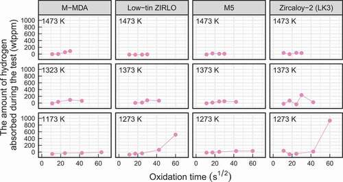
The amounts of hydrogen absorbed by the high-burnup advanced fuel cladding tube specimens during the oxidation tests are depicted in as a function of the square root of oxidation time. These amounts were obtained by subtracting the initial hydrogen concentrations from the hydrogen concentrations in the cladding tube specimens after the oxidation tests were completed. From this figure, it can be observed that the hydrogen absorption during oxidation tests was not significant except for the high-burnup low-tin ZIRLO cladding tube specimen and the high-burnup Zircaloy-2 (LK3) cladding tube specimen that were oxidized at a temperature of 1273 K for a duration of 3600 s.
Figure 6. Amounts of hydrogen absorbed by the high-burnup advanced fuel cladding tube specimens during the oxidation tests as a function of the square root of oxidation time.
4. Discussion
4.1. Oxidation kinetics
It is generally accepted that the high-temperature oxidation of zirconium alloys is caused by the diffusion of oxygen anions through the ZrO lattice [Citation3,Citation11,Citation17]. Therefore, the reaction rate of zirconium alloy that is oxidized at temperatures higher than 1173 K is generally described using the following parabolic expression [Citation3,Citation10,Citation11,Citation17]:
where denotes the weight gain per unit surface area,
denotes the parabolic rate constant for the weight gain, and
denotes the oxidation time. A linear relation between the weight gain and the square root of oxidation time is depicted in , except for both the high-burnup and the unirradiated low-tin ZIRLO cladding tube specimens that were oxidized at a temperature of 1273 K and for the high-burnup Zircaloy-2 (LK3) cladding tube specimens that were oxidized at temperatures equal to or lower than 1373 K. Further, a more careful evaluation of the linear relation in based on the coefficient of determination
suggests that the weight gain of all the examined advanced fuel cladding tube specimens tended not to follow the linear relation at temperatures of 1173 and 1273 K for durations equal to or longer than 1800 s. The deviation from the linear relation that was observed for the high-burnup low-tin ZIRLO and Zircaloy-2 (LK3) cladding tube specimens oxidized at a temperature of 1273 K for a duration of 3600 s and for the unirradiated low-tin ZIRLO cladding tube specimen oxidized at a temperature of 1273 K for a duration of 7200 s is considered to be caused by the breakaway oxidation as will be discussed in Section 4.2. The weight gain of the high-burnup Zircaloy-2 (LK3) cladding tube specimen was observed to be relatively large and deviate from the linear relation at temperatures of 1273 and 1373 K for a duration of 1800 s, though the breakaway oxidation was not observed for these oxidation conditions. Therefore, in this study, oxidation kinetics of the advanced fuel cladding tube specimens was estimated by assuming the parabolic rate law for the weight gain data at temperatures of 1173, 1273, and 1473 K for durations equal to or shorter than 900 s and at temperatures of 1323 and 1373 K for durations equal to or shorter than 1800 s. For the case of the high-burnup Zircaloy-2 (LK3) cladding tube specimen, oxidation kinetics at a temperature of 1373 K was estimated by assuming the parabolic rate law for the weight gain data for durations equal to or shorter than 900 s.
A comparison of the parabolic rate constants for the weight gain between the high-burnup advanced fuel cladding tube specimens and the unirradiated advanced fuel cladding tube specimens is depicted in . The standard errors of the parabolic rate constants for the weight gain are denoted by the error bars. The parabolic rate constants for the weight gain of the unirradiated Zircaloy-4 cladding tube specimens reported by Nagase et al. [Citation26] are denoted as reference. For unirradiated M5, the parabolic rate constants for the weight gain that were evaluated using the weight gain data reported by Chuto et al. [Citation17] are shown as reference. At a temperature of 1473 K, the oxidation kinetics of the high-burnup advanced fuel cladding tube specimens was observed to be equal to that of the unirradiated advanced fuel cladding tube specimens, as depicted in . At temperatures equal to or lower than 1373 K, the oxidation kinetics of the high-burnup advanced fuel cladding tube specimens tended to be slower than those of the unirradiated advanced fuel cladding tube specimens. This trend was observed to be consistent with the oxide growth that was mentioned in Section 3.3. The thicknesses of HT oxide at the outer surface of the high-burnup advanced fuel cladding tube specimens were observed to be thinner than those of the unirradiated advanced fuel cladding tube specimens at temperatures equal to or lower than 1373 K. This trend is considered to be caused by the protective effect of the corrosion layer on oxidation [Citation3,Citation17,Citation28–Citation30]. In contrast to the outer surface, the thicknesses of HT oxide at the inner surface of the high-burnup advanced fuel cladding tube specimens were thicker than those of the unirradiated advanced fuel cladding tube specimens, as depicted in . The inner surface of the high-burnup advanced fuel cladding tube specimens was ground to completely eliminate both the fuel pellet and the pellet–cladding bonding layer. This grinding is considered to form a rough inner surface having a large surface area. As the surface area increases, the reaction with steam also increases, which can lead to the acceleration of the oxidation. Therefore, the thick HT oxide at the inner surface may be caused by increased roughness of the surface that can be attributed to grinding. Nagase et al. reported that pre-hydriding at less than 800 wtppm increased the weight gain by less than 5% within a duration of a few minutes [Citation30]. However, whereas it is considered that the corrosion layer exhibited the protective effect on oxidation, the increase in weight gain or oxidation kinetics caused by pre-hydriding was not observed. Thus, it is considered that the burnup extension up to 85 GWd/t does not significantly increase the oxidation kinetics of the advanced fuel cladding tubes.
Figure 7. Comparison of the parabolic rate constants for the weight gain between the high-burnup advanced fuel cladding tube specimens and the unirradiated advanced fuel cladding tube specimens. Error bars denote the standard errors of the parabolic rate constants for the weight gain. The parabolic rate constants for the weight gain of the unirradiated Zircaloy-4 cladding tube specimens reported by Nagase et al. [Citation26] are shown as reference. For unirradiated M5, the parabolic rate constants for the weight gain were evaluated using the weight gain data reported by Chuto et al. [Citation17].
![Figure 7. Comparison of the parabolic rate constants for the weight gain between the high-burnup advanced fuel cladding tube specimens and the unirradiated advanced fuel cladding tube specimens. Error bars denote the standard errors of the parabolic rate constants for the weight gain. The parabolic rate constants for the weight gain of the unirradiated Zircaloy-4 cladding tube specimens reported by Nagase et al. [Citation26] are shown as reference. For unirradiated M5, the parabolic rate constants for the weight gain were evaluated using the weight gain data reported by Chuto et al. [Citation17].](/cms/asset/670395d9-6be0-48ef-868b-0c95f802878f/tnst_a_1613268_f0007_oc.jpg)
All the oxidation kinetics depicted in are presented in to compare oxidation kinetics between the advanced fuel cladding tube specimens and the unirradiated Zircaloy-4 cladding tube specimens. At a temperature of 1473 K, the oxidation kinetics of the high-burnup advanced fuel cladding tube specimens was almost equivalent to that of the unirradiated Zircaloy-4 cladding tube specimens reported by Nagase et al. [Citation26]. However, at temperatures equal to or lower than 1373 K, the oxidation kinetics of the high-burnup advanced fuel cladding tube specimens tended to be slower than that of the unirradiated Zircaloy-4 cladding tube specimens. For the unirradiated advanced fuel cladding tube specimens, the oxidation kinetics was comparable to that of the unirradiated Zircaloy-4 cladding tube specimens except for the M5 cladding tube specimens. For the unirradiated case, the lowest oxidation kinetics could be observed in the M5 cladding tube specimens at temperatures equal to or lower than 1373 K. This trend was consistent with that observed in previous studies [Citation16,Citation31]. Thus, it is considered that the use of the advanced fuel cladding tubes does not significantly increase the oxidation kinetics in comparison with the use of the conventional Zircaloy.
Figure 8. Temperature dependence of the parabolic rate constants for the weight gain of the advanced fuel cladding tube specimens. The parabolic rate constants for the weight gain of the unirradiated Zircaloy-4 cladding tube specimens reported by Nagase et al. [Citation26] are shown as reference. For unirradiated M5, the parabolic rate constants for the weight gain were evaluated using the weight gain data reported by Chuto et al. [Citation17].
![Figure 8. Temperature dependence of the parabolic rate constants for the weight gain of the advanced fuel cladding tube specimens. The parabolic rate constants for the weight gain of the unirradiated Zircaloy-4 cladding tube specimens reported by Nagase et al. [Citation26] are shown as reference. For unirradiated M5, the parabolic rate constants for the weight gain were evaluated using the weight gain data reported by Chuto et al. [Citation17].](/cms/asset/440b760b-1a12-4be4-a3bc-79819db52692/tnst_a_1613268_f0008_oc.jpg)
The oxidation kinetics estimated using the Baker–Just equation [Citation6] and the Cathcart–Pawel equation [Citation9] is denoted as black solid lines in . These equations are defined at temperatures higher than 1273 K. Thus, for these equations, the oxidation kinetics was extrapolated to temperatures lower than 1273 K, and the extrapolated oxidation kinetics was expressed as black dashed lines. The Cathcart–Pawel equation is generally recognized to be the most reliable tool for evaluating the oxidation kinetics of Zircaloy-4 [Citation2,Citation26]. The Cathcart–Pawel equation gives comparable oxidation kinetics at a temperature of 1473 K and conservative oxidation kinetics at temperatures lower than 1473 K in comparison with the oxidation kinetics of all the examined high-burnup advanced fuel cladding tube specimens. The Baker–Just equation gives conservative oxidation kinetics at temperatures ranging from 1173 to 1473 K in comparison with the oxidation kinetics of all the examined high-burnup advanced fuel cladding tube specimens.
4.2. Breakaway oxidation
The breakaway oxidation is characterized by a significant increase in oxidation kinetics and hydrogen absorption [Citation10,Citation18,Citation26]. 200-wtppm hydrogen absorption was used as a metric for detecting breakaway oxidation in previous studies [Citation18,Citation19]. A significant increase in weight gain and significant hydrogen absorption of greater than 200 wtppm were observed for the high-burnup low-tin ZIRLO and Zircaloy-2 (LK3) cladding tube specimens that were oxidized at a temperature of 1273 K for a duration of 3600 s, as depicted in and . Metallographs of the transverse cross-sections of these specimens are depicted in . In these specimens, porous oxide layers with circumferential cracks and wavy interfaces between the oxide layer and metal, which are typical features of the breakaway oxidation [Citation10,Citation18,Citation19,Citation21,Citation26], were observed. Therefore, a breakaway oxidation was confirmed for these cladding tube specimens. However, it should be noted that even after the breakaway oxidation, the weight gains of these specimens were comparable to those of the unirradiated advanced cladding tube specimens, as depicted in . also depicted a significant increase in weight gain of the unirradiated low-tin ZIRLO cladding tube specimen that was oxidized at a temperature of 1273 K for a duration of 7200 s. The aforementioned typical features of the breakaway oxidation were also observed for this specimen using metallographs of the transverse cross-sections of this specimen. Therefore, though the amount of hydrogen absorption was not measured, it is considered that the breakaway oxidation occurred for this specimen.
Figure 9. Metallographs of the transverse cross-sections of the high-burnup low-tin ZIRLO and Zircaloy-2 (LK3) cladding tube specimens after being oxidized at 1273 K for 3600 s.
From the safety viewpoint, the onset time of breakaway oxidation was considered to be important because the breakaway oxidation was accompanied by significant embrittlement of the cladding tubes. The onset times of breakaway oxidation that were defined as 200-wtppm hydrogen pickup or weight gain of 100 gm−2 were estimated to be 3600–3800 s for the unirradiated Zircaloy-4 cladding tubes [Citation18,Citation26], (3100 300) s for the unirradiated ZIRLO cladding tubes [Citation18,Citation19], and 5000 s for the unirradiated M5 cladding tubes [Citation20] at isothermal oxidation temperatures of 1243–1273 K. In this study, breakaway oxidation was not observed at oxidation times of shorter than the aforementioned onset times for the high-burnup advanced fuel cladding tube specimens. Therefore, it can be considered that the onset time of the breakaway oxidation of the fuel cladding tubes is not significantly reduced by extending the burnup to 85 GWd/t and using the advanced fuel cladding tubes.
5. Conclusion
To evaluate the oxidation behavior of high-burnup advanced fuel cladding tubes in high-temperature steam, laboratory-scale isothermal oxidation tests were performed using the following advanced fuel cladding tubes with burnups of up to 85 GWd/t: M-MDA, low-tin ZIRLO, M5, and Zircaloy-2 (LK3). These oxidation tests were performed in steam-flowing conditions at temperatures ranging from 1173 to 1473 K for durations between 120 and 4000 s. In comparison with the unirradiated Zircaloy-4 cladding tube specimens that were reported in a previous study, the oxidation kinetics of the high-burnup advanced fuel cladding tube specimens that was estimated by assuming the parabolic rate law was comparable at a temperature of 1473 K and tended to be slower at temperatures equal to or lower than 1373 K. Further, whereas it is considered that the corrosion layer exhibited a protective effect on oxidation, an increase in either the weight gain or oxidation kinetics that can be attributed to pre-hydriding was not observed. Therefore, it is considered that the oxidation kinetics of the fuel cladding tubes under the high-temperature steam is not significantly increased by extending the burnup to 85 GWd/t and using the advanced fuel cladding tubes. The Cathcart–Pawel equation gives comparable oxidation kinetics at a temperature of 1473 K and conservative oxidation kinetics at temperatures lower than 1473 K in comparison with the oxidation kinetics of all the examined high-burnup advanced fuel cladding tube specimens. The Baker–Just equation gives conservative oxidation kinetics in comparison with the oxidation kinetics of all the examined high-burnup advanced fuel cladding tube specimens at temperatures ranging from 1173 to 1473 K. The onset times of the breakaway oxidations of the high-burnup advanced fuel cladding tube specimens were comparable to those of the unirradiated Zircaloy-4 cladding tubes that were reported in previous studies. Thus, it can be said that the onset time of the breakaway oxidation of the fuel cladding tubes is not significantly reduced by extending the burnup to 85 GWd/t and using the advanced fuel cladding tubes.
Acknowledgments
This study was performed under the research entrusted by Secretariat of Nuclear Regulation Authority. The authors would like to acknowledge and express their appreciation for the time and effort devoted by numerous engineers and technicians of the Department of Criticality and Hot Examination Technology, JAEA.
Disclosure statement
No potential conflict of interest was reported by the authors.
Related Research Data
References
- Chung HM. Fuel behavior under loss-of-coolant accident situations. Nucl Eng Technol. 2005 Aug;37:327–362.
- Meyer R. Fuel behavior under abnormal conditions. Washington (DC): The U.S. Nuclear Regulatory Commission; 2014. (Report no. NUREG/KM-0004).
- Fuketa T, Nagase F. Behavior of fuel with zirconium alloy cladding in reactivity-initiated accident and loss-of-coolant accident. ASTM STP. 2018;1597:52–92.
- OECD/NEA. Nuclear fuel behaviour in Loss-of-coolant Accident (LOCA) Conditions: state-of-the-art Report. Paris (France): Oganisation for economic co-operation and development nuclear energy agency; 2009.
- OECD/NEA. Nuclear fuel safety criteria technical review. Second ed. Paris (France): Oganisation for economic co-operation and development nuclear energy agency; 2012.
- Baker L, Just LC. Studies of metal-water reaction at high temperatures. III. Experimental and theoretical studies of the zirconium-water reaction. Argonne (Illinois): Argonne National Laboratory; 1962. (Report no. ANL-6548).
- Ballinger RG, Dobson WG, Biederman RR. Oxidation reaction kinetics of Zircaloy-4 in an unlimited steam environment. J Nucl Mater. 1976;62:213–220.
- Kawasaki S, Furuta T, Suzuki M. Oxidation of Zircaloy-4 under high temperature steam atmosphere and its effect on ductility of cladding. J Nucl Sci Technol. 1978 Aug;15:589–596.
- Pawel RE, Cathcart JV, McKee RA. The kinetics of oxidation of Zircaloy-4 in steam at high temperatures. Electrochem Soc. 1979 Jul;126:1105–1111.
- Leistikow S, Schanz G. Oxidation kinetics and related phenomena of Zircaloy-4 fuel cladding exposed to high temperature steam and hydrogen-steam mixtures under PWR accident conditions. Nucl Eng Des. 1987 Aug;103:65–84.
- Uetsuka H, Hofmann P. High-temperature oxidation kinetics of Zircaloy-4 in oxygen/argon mixtures. J Nucl Mater. 1989;168:47–57.
- The Nuclear Safety Commission of Japan. Treatment of high burn-up fuels for safety evaluation in reactivity-initiated events of commercial LWR. Japan: The Nuclear Safety Commission of Japan; 1998. in Japanese.
- Mardon JP, Charquet D, Senevat J. Influence of composition and fabrication process on out-of-pile and in-pile properties of M5 alloy. ASTM STP. 2000;1354:505–524.
- Mutyala M. Westinghouse fuel direction. Proc. 2004 International Meeting on LWR Fuel Performance; 2004 Sep 19–22; Orlando (Florida).
- Watanabe S, Kido T, Arakawa Y. Performance of M-MDA cladding in the commercial reactor up to 73 GWd/tU. Proc. WRFPM2008; 2008 Oct 19–22; Seoul (Korea).
- Steinbrück M, Vér N, Große M. Oxidation of advanced zirconium cladding alloys in steam at temperatures in the range of 600–1200°C. Oxid Met. 2011;76:215–232.
- Chuto T, Nagase F, Fuketa T. High temperature oxidation of Nb-containing Zr alloy cladding in LOCA conditions. Nucl Eng Technol. 2009;41:163–170.
- Billone M, Yan Y, Burtseva T, et al. Cladding embrittlement during postulated loss-of-coolant accidents. Washington (DC): The U.S. Nuclear Regulatory Commission; 2008. (Report no. NUREG/CR-6967, ANL-07/04).
- Billone MC, Yan Y, Burtseva TA, et al. Cladding behavior during postulated loss-of-coolant accidents. Washington (DC): The U.S. Nuclear Regulatory Commission; 2016. (Report no. NUREG/CR-7219, ANL-16/09).
- Vandenberghe V, Brachet JC, Le Saux M, et al. Sensitivity to chemical composition variations and heating/oxidation mode of the breakaway oxidation in M5 cladding steam oxidized at 1000°C (LOCA conditions). Proc. TopFuel2012; 2012 Sep 2–6; Manchester (United Kingdom).
- Yamato M, Nagase F, Amaya M. Reduction in the onset time of breakaway oxidation on Zircaloy cladding ruptured under simulated LOCA conditions. J Nucl Mater. 2014;445:78–83.
- Sato D, Kido T, Mazaki Y. In-pile behavior of M-MDA, advanced PWR fuel cladding irradiated up to 73 GWd/t(R) in a commercial reactor. Proc. WRFPM2011; 2011 Sep 11–14; Chengdu (China).
- Adamson RB, Rudling P. 4 - Properties of zirconium alloys and their applications in light water reactors (LWRs). In: Murty KL, editor. Woodhead Publishing Series in Energy, Materials ageing and degradation in light water reactors. Sawston, Cambridge: Woodhead Publishing; 2013. p. 151–245.
- Lemaignan C. 2.07 - Zirconium alloys: properties and characteristics. In: Konings RJM, editor. Comprehensive nuclear materials. Amsterdam: Elsevier; 2012. p. 217–232.
- Uetsuka H. Oxidation of Zircaloy-4 under limited steam supply at 1000 and 1300°C. Karlsruhe (Germany): Institut fur Material- und Festkorperforschung Projekt Nukleare Sicherheit; 1984. (Report no. KfK 3848).
- Nagase F, Otomo T, Uetsuka H. Oxidation kinetics of low-Sn Zircaloy-4 at the temperature range from 773 to 1,573 K. J Nucl Sci Technol. 2003;40:213–219.
- Chuto T. Oxidation of high burnup fuel cladding in LOCA conditions. presented at FSRM2010: 2010 May 19–20; Mito (Japan).
- Ozawa M, Takahashi T, Homma T, et al. Behavior of irradiated Zircaloy-4 fuel cladding under simulated LOCA conditions. ASTM STP. 2000;1354:279–299.
- Aomi M, Nakatsuka M, Komura S, et al. Behavior of BWR fuel cladding tubes under simulated LOCA conditions. Proc. ICONE-7; 1999 Apr 19–23; Tokyo (Japan).
- Nagase F, Otomo T, Uetsuka H. Experiments on high burnup fuel behavior under LOCA conditions at JAERI. Proc. 2000 International Topical Meeting on Light Water Reactor Fuel Performance; 2000 Apr 10–13; Park City, Utah (USA).
- Portier L, Bredel T, Brachet J, et al. Influence of long service exposures on the thermal-mechanical behavior of Zy-4 and M5 alloys in LOCA conditions. J ASTM Intl. 2005;2:1–24.