
 ?Mathematical formulae have been encoded as MathML and are displayed in this HTML version using MathJax in order to improve their display. Uncheck the box to turn MathJax off. This feature requires Javascript. Click on a formula to zoom.
ABSTRACT
In this research work, experimental studies on remote start-up of Joule Heated Ceramic Melter (JHCM) used for vitrification of radioactive liquid waste (RLW) were carried out. Numerical simulations were performed to understand the mode of heat transfer and improve the energy efficiency of JHCM during start-up. Preformed glass frit used for vitrification, is heated using Silicon–Carbide (SiC) resistance heaters installed in plenum region of the JHCM. Experiments were carried out to understand the heat transfer phenomena during the start-up of an industrial scale JHCM. The temperature was monitored at nine different locations to estimate heat losses from the melter, and based on this data, energy apportionment of the start-up heating was carried out. Different parameters that affect the efficiency of the start-up heating are identified and the effect of these parameters on the efficiency of the start-up heating is quantified. The effect of change in the geometry of the prefabricated slot in the refractory on the overall thermal performance of the melter is estimated. The results show that by deploying a circular geometry in the prefabricated slots of the refractory, the heat flux, heating rate and thermal efficiency of the melter can be increased by 44%, 10.4%, and 35%, respectively.
1. Introduction
Radioactive Liquid Waste (RLW) generated during reprocessing of the spent nuclear fuel is conditioned by fixing the radionuclides in a glass matrix by a process called vitrification. Joule Heated Ceramic Melter (JHCM) based continuous vitrification technology with its high throughput, melting temperature and suitability to remote operations, is the best available option for the management of RLW. Vitrification is carried out at a temperature of about 1000°C. JHCM utilizes the ability of glass to conduct electricity at higher temperatures. It is provided with electrodes placed opposite to each other for passing alternating current. Heat generated in accordance with the Joule principle is used for the evaporation and subsequent calcination of RLW. As the glass frit charged into the melter cavity is an electric insulator at room temperature, start-up heating is required to bring the temperature of the glass to conducting zone [Citation1–Citation7].
The resistivity of glass is determined by two parallel electrodes immersed into the glass melt [Citation8]. As shown in , glass conducts electricity only above temperatures of 600°C. Resistance heaters made up of Silicon Carbide (SiC) are provided for raising the temperature of the glass frit to conducting zone as shown in ). On attaining a temperature, sufficient for glass to conduct electricity, the Inconel© electrodes are energized as shown in ).
Figure 1. Resistivity of Glass as a function of temperature for SiO2-Na2O-TiO2-Fe2O3-based glass
Figure 2. Industrial-scale JHCM used for experiments (a) Start-up heating using plenum heaters; (b) Electrode heating
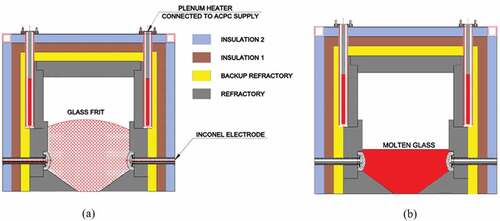
The total power required depends upon the resistivity of the glass, geometry of the melter, and heat losses above and below the plenum zone. The heaters placed in the plenum region are used for start-up heating of JHCM to remove the moisture present in the refractory and also to heat the frozen glass during regular operation [Citation1]. Resistance heaters are inserted in Kanthal© tubes and are placed in a cavity in the plenum region of the melter (hence the name plenum heaters). The space between the heaters and tubes and between the tubes and the refractory blocks is occupied by air. Power is supplied to plenum heaters and the heat generated in the plenum heaters is used to heat the refractory blocks. The refractory blocks in turn transfer heat to glass frit. Heat is transferred to glass frit by walls in the plenum region through radiation and conduction. The apportionment of energy transferred to glass frit between these modes was not possible in industrial-scale melter. In order to determine the energy apportionment by radiation and convection, a set-up was fabricated and deployed to study the phenomenon of start-up heating by replicating industrial-scale heating. The studies reported in literature provide different methods of start-up heating and optimization of the plenum heater section [Citation2–Citation8]. Majority of the studies recommended using resistance heaters [Citation1–Citation8]. Microwave heating is also deployed to simplify the plenum section size by optimizing plenum heater design [Citation2]. Till date, no literature is available on factors affecting the start-up heating. The efficiency of the start-up heating is affected by various parameters like the skin losses, the negative pressure in the melter, the air gap between the heater and Kanthal© tubes and the geometries of the heater and pre-fabricated slots. Though the effect of other parameters on the overall heat flux can be easily determined for a given system, the determination of the effect of air gap and geometry of the heaters and pre-fabricated refractory slots are not feasible, as mapping of temperature on inside walls of melter cavity at high temperature is difficult. This necessitates the modeling of start-up heating and its validation using experimental results.
The objective of this work was to determine the contribution of different modes of heat transfer in raising the temperature of glass frit. An understanding of this fundamental phenomenon will result in devising methods that can be adopted to increase the thermal efficiency of the start-up heating with optimum plenum heater temperatures. The study is focussed on a complete understanding of the heat transfer mechanism in a continuous vitrification equipment during its start-up stage and methods of improving it.
2. Experimental set-up
2.1. Experiments on industrial scale melter
In JHCM, the glass frit is contained within the cavity made of refractory bricks. The refractory blocks are followed by back up refractory, which is provided to prevent glass migration to the outer layers. The insulation layers 1 and 2 are provided to prevent heat loss. The physical properties of the materials are given in . The insulation layers are finally enveloped by a Stainless Steel (SS) sheets. The insulation of JHCM is designed to reduce skin losses. The glass frit is initially heated using resistance heaters. Once the glass reaches a conducting temperature, alternating current is passed between two submerged electrodes, placed opposite to each other.
Table 1. Physical properties of glass and insulation materials used for modelling
As the refractory is a poor thermal conductor, the rate at which the temperature is increased during start-up is crucial, as a sudden increase in temperature can lead to thermal stresses due to a high-temperature gradient across its thickness. In extreme cases, this can cause cracks in refractories, which is detrimental to the containment. The rate of increase in heater temperature was limited to 5° C/hr. To achieve the purpose of controlled heating, plenum heaters were provided with a thyristor control. Also, the glass pool, plenum heater and electrode temperatures were monitored at regular intervals with the help of thermocouples. The surface temperature of the SS enclosure of the melter was monitored to determine the surface heat losses. The external face walls of the melter were monitored with thermal imaging cameras to determine the effectiveness of the insulation layers and detect any point of abnormal heat loss.
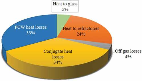
Based on the experiments, the surface heat loss from JHCM was estimated. Based on the temperature of the face walls, the surface-to-air heat transfer coefficient was estimated. The off-gas losses were determined by measuring the air leakage into the melter and its temperature. The energy apportionment is shown in .
Figure 3. Heat apportionment of start-up heating
2.2. Determination of the contribution of different modes of heat transfer to glass frit
The experimental setup used consisted of a SS enclosure, refractory blocks, and plenum heaters of 3 kW capacity each, made up of Silicon Carbide (SiC). The heaters were enclosed in Kanthal© tubes and connected to Alternating Current Power Control (ACPC) panels. The hot face temperature of the refractory blocks was measured at nine different locations using K-type thermocouples having an accuracy of ±2°C over the range of 0–1200°C to determine the vertical and horizontal distribution of temperature. The outputs of the thermocouples were connected with a Data Acquisition System, and the temperature was monitored continuously as shown in .
Figure 4. Schematic of experiment used for determination of the mode of heat transfer
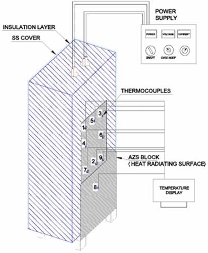
All the faces of the blocks were insulated with fibre wool except one face that was used for heating the glass frit to simulate the heat transfer mechanism in the melter. The temperature of the resistance heaters was varied by varying the power input.
2.3. Experimental procedure
The power to the plenum heaters was increased at a rate of 0.1 kW/hr at regular intervals, and the system was allowed to achieve a steady state. The temperature of the refractory blocks increased linearly with heater power. The rise in temperature of the thermocouples and their steady-state temperatures were monitored.
The intent of this experiment was to measure the temperatures at different locations of the plenum set-up, used for validating the data generated from simulation and to determine the mode of heat transfer to glass frit. Glass frit was filled in the cavity adjacent to the refractory blocks up to a height of 500 mm from the bottom. The heater temperatures were raised, and the temperatures of thermocouples were monitored. Data were generated to determine the contribution of different modes of heat transfer to the glass frit.
3. Mathematical model to determine heat transfer mechanism and contribution of different types of heat transfer to heat flux
The heat transfer mechanism in a JHCM is radiation between walls of refractory in a cubical enclosure, conduction between layers of refractory and insulation materials and convection existing on the outer surface.
3.1 Literature related to heat transfer mechanism understanding
The phenomena viz., conduction, convection, and radiation occur on the walls of the melter. The heat is predominantly transferred by radiation. The study is restricted to heat transfer in enclosures. Extensive numerical investigations and experimental work are carried out to understand mechanism of heat transfer in different geometries [Citation9–Citation18]. Most of the available literature focuses on the heating of a cylinder with annular spaces. Many numerical simulation studies were carried out by researchers, addressing the effect of temperature and pressure on the heating of coaxial cylinders. The study focuses on the influence of the air gap on the thermal efficiency of the heating.
3.2 Model development
The mathematical model developed treats the heat balance using the standard parabolic heat equation [Citation19]. The coupled differential equations were solved numerically for surface radiosity ‘J’ and Temperature ‘T’. The model provides an insight into the transient and steady-state behaviour of plenum heaters from start-up conditions to the steady-state operating conditions. The following assumptions were made for developing the model:
The Kanthal tube is considered as a heat generating source, and it is ideally transferring all the heat generated to the system.
There are no air gaps between the insulation layers, thereby making them opaque to radiation and convection.
Plenum heater module is smeared out into a volume source, though the heating element is in the shape of a U bar. This is assumed to avoid computational difficulty as the size of the heater was far lesser (1:10) compared to the size of the experimental setup.
The governing equations for the model are
where ρ is density (kg m−3), Cp is the specific heat capacity at constant pressure (J kg−1 K−1), T is the temperature (K), k is the thermal conductivity (W m−1 K−1), and Q is the heat source (J).
Heat losses by means of convection and radiation from side, top and bottom walls were independently incorporated as given by EquationEqs. (2)(2)
(2) & (Equation3
(3)
(3) ).
where h is the heat transfer coefficient (W m−2 K−1), Text is the external temperature (K), ε surface emissivity, is the unit normal vector from surface and σ is the Stephan Boltzmann constant. Surface to surface radiation for cavity was also incorporated as given by EquationEqs. (4)
(4)
(4) , (Equation5
(5)
(5) ) & (Equation6
(6)
(6) ).
where εb is emissivity of a black body, n is the refractive index of the surface, G is irradiation in W and J0 is initial radiosity (W m−2). The simulation was carried out using COMSOL software. COMSOL detects the geometry and predicts the type of mesh suitable for a given geometry, based on physics involved, dimensions and positions.
The model uses heat transfer physics with discrete ordinates method (DOM) of evaluation for the surface-to-surface radiation. As the geometry is highly occluded, it employs a hemi cube method of estimating radiation patches. The discretization scheme used for temperature estimation is quadratic, while for surface radiosity it is linear. The heat source term (volumetric) was given in the Kanthal tubes, and the heat loss term was incorporated on the respective surfaces. The losses were mainly by convective cooling and surface to ambient radiation.
3.3 Boundary conditions
A three-dimensional coordinate system is used for computation. The initial temperature on all the boundaries is 25°C. Constant heat flux from the Kanthal tubes is assumed for computation. Conjugate heat transfer is given as boundary condition for skin losses from the outer surface. Heat transfer coefficient of 1.2 W m−2 K−1, 5.5 W m−2 K−1 and 1.7 W m−2 K−1 for bottom, vertical, and top plates of melter were evaluated theoretically using EquationEq. 7(7)
(7) and incorporated into the model.
where Nu is Nusselt Number, Gr is Grashof Number, Pr is Prandtl Number, and a & n are arbitrary constants which vary according to the orientation of plates (vertical or horizontal).
3.4 Mesh dependency studies
The mesh dependency study was carried out with four meshes; coarse, normal, fine, and extra-fine mesh and by considering all the three modes of heat transfer. The temperature profiles of thermocouple 5, 2, and 8 were compared for different meshes as shown in .
Figure 5. Temperature profiles of thermocouples 5, 2 and 8 for different meshes (coarse, normal, fine, and extra-fine)
As can be seen from the graph, no significant deviation is observed in the temperature obtained by adopting the normal, fine and extra-fine mesh. For coarse mesh, the deviation is around 16% and for normal mesh, it is 7%. As fine and extra-fine mesh do not have a significant difference, the fine mesh was chosen for minimizing the time required for simulation. The mesh size distribution is given in .
Figure 6. Fine mesh view of the model
After carrying out mesh dependency test, a total number of 8718 tetrahedral elements were created in the model. The elements' sizes near the heat source region were in the range of 9.31–128 mm, for steeper gradient detection in plenum heater region, while in the other regions, it was in the range of 41.9–233 mm. An average mesh quality of 0.556 was achieved.
3.5 Validation of model
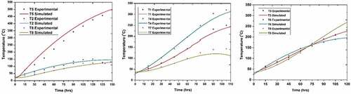
Validation of the model requires a comparison of temperature obtained through simulations with that of actual experiments. Nine thermocouples were used at different locations to record the temperature of the plenum heaters setup during experiments. The same points were located inside the model for validation of the data generated from model in addition to the temperatures of Alumina-Zirconia-Silica (AZS) blocks, inside Kanthal tubes and surface temperatures.
The model was validated by comparing the calculated temperatures with experimental data, and the results are in good agreement with the experimental findings.
shows the thermocouple temperatures obtained from experiment and simulation.
Figure 7. Validation of model with experimental data
3.6 Simulation
Boundary conditions were incorporated for the open face of the model. Tetrahedral geometry was used for meshing. The 3D geometry was meshed based on geometry, physics, dimensions, and positions. The fine mesh was selected, and all the dimensions were as per the experimental condition. The study was done by coupling the radiation of the surfaces, the convection in air and conduction between solids.
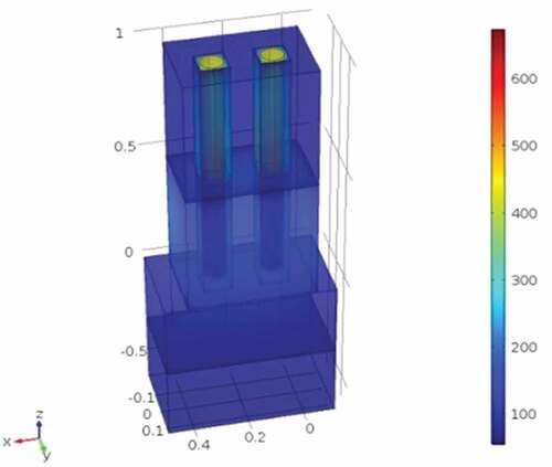
After simulating the plenum heaters as per the stipulated condition, the temperature profile shown in was obtained.
Figure 8. Simulated PH Temperature contours (Rainbow Legend – Celsius scale)
4. Results and discussions
During the start-up operation of JHCM, it was observed that only 5% of the heat supplied to the plenum heaters could be utilised for heating the glass frit. Experiments were devised to analyse the effect of different parameters like reducing the skin losses by insulating the top of the melter, reducing the heat losses from the system by optimizing the negative pressure of the melter, optimizing the gap between heaters and Kanthal tubes and to determine the dominant mode of heat transfer in the system.
4.1 Reducing the skin losses from the top of melter
The skin losses from the side, bottom, and top of the melter were determined and were found to be 8.4, 1 and 2.1 kW, respectively. Melter top face and top half section of side face contributed to higher heat losses. The losses can be minimised by providing glass fibre insulation of 50 mm thickness, during start-up. Subsequently, these insulations can be remotely removed. The additional insulation will reduce heat losses to 1.5, 0.9 and 3.4 kW from side, bottom, and top, respectively. This reduction will allow the plenum heaters to serve their purpose at lower temperatures.
4.2 Optimization of negative pressure of JHCM
In JHCM the negative pressure must be kept better than 50 mm water column below atmospheric pressure to prevent pressurisation of the equipment and subsequent release of radioactivity inside the cell. This condition also ensures that the gaseous radioactive effluents generated during the process are routed through an elaborate off-gas cleaning system before finally discharged into the atmosphere. To reduce air ingress in JHCM, it is enclosed by SS sheets as the internal layers of refractory material do not provide sufficient airtightness, due to the inherent gaps that exist between the refractory blocks and insulation layers [Citation2].
However, various penetrations into the SS casing of the JHCM like electrodes, feed nozzles, off-gas nozzles, level probes, thermowells, etc., provide a path for air ingress. The optimised negative pressure of the JHCM is a balance between preventing pressurisation and minimizing air ingress. Increased air ingress will result in heat losses from JHCM. By reducing the negative pressure in melter, the ingress of air into the furnace is reduced. This reduces the heat losses from the equipment. shows the heat losses in JHCM with respect to air ingress and negative pressure in JHCM.
Figure 9. Off-gas ingression and heat losses vs Negative pressure in the melter
The negative pressure in JHCM is an optimized value to prevent carryover of entrained particles during boiling of radioactive waste and containing the radioactivity within the equipment. In regular operations, the negative pressure is maintained between −25 and −40 mm of the water column, whereas during start-up heating, it should be to maintain about −10 mm of the water column.
4.3 Heat transfer mechanism and contribution of different modes to total heat dissipation
The plenum heaters are located in the top section of the melter. Radiation is the predominant mode of heat transfer between the heaters and Kanthal tubes. The transfer from tube to the refractory is also by radiation. The intent of the study was to determine the predominant mode of heat transfer between refractory and glass beads. The emissivity of the wall surface is 0.58. Radiation contributes 74% of overall heat transfer to glass beads at temperatures up to 500°C. Beyond this, the contribution by radiation increases to ~90%. The overall heat flux decreases drastically if only radiation is considered. If conjugate heat transfer is considered, the heat flux increases by 30%.
At plenum heater temperature of 575°C, the maximum face temperature of the refractory block was 400°C. The temperature of the AZS blocks increased linearly with heater power. The rise in temperature of the thermocouples and their steady-state temperatures were in line with the position, indicating the absence of any abnormalities.
Change in temperature with time predicted from the simulation is compared with experimental data for the thermocouple positions T1-9, as shown in . Thermocouple-8, which is farthest on the face of the AZS blocks, resembles almost similar values and pattern except for the initial gap. The initial gap is attributed to the transient heat transfer between the blocks and the heat source.
Figure 10. (a) Prefabricated square slots for placing of PH with a gap 6–26 mm. (b) Circular Slots for placing of PH
Deviation of the predicted values from the experimental values is ± 7% for T5 location. For other locations, for given power input, the deviation in the predicted values compared to experimental values is 2%. The variation observed in the rate of change in temperatures for simulated and experimental results is because of the type of heat input given to the heaters, which in actual experiments is changing gradually at a constant rate till it reaches its maximum power of 2.5 kW.
4.4 Change of the geometry of prefabricated slots from square to circular
The cylindrical Kanthal tubes are placed in prefabricated slots in the refractory. The type of geometry and dimensions of the slots play a very important role in improving or downgrading the thermal performance and hence, the efficiency of the plenum heating.
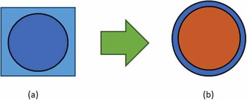
The size of the heaters and minimum clearance limits determines the dimensions of the slots. However, for any given dimension, the shape of the slots can be square or circular. The validated model was used to study the effect of change in geometry of the prefabricated slot on the overall thermal performance of the plenum heating section. The original square slots had each side of 100 mm length. The slots fabricated in the melter have to provide enough clearance for insertion and removal of Kanthal tubes remotely. Remote Handling trials were carried out, and it was realised that a minimum clearance of 1.5 mm between the tubes and slots was required for insertion and removal of these Kanthal tubes. Hence, the minimum diameter of the slot was fixed as 93 mm. Studies were carried out to examine the influence of air gap and change in slot geometry by using the validated model as shown in (,).
4.5 Variation of the air gap between kanthal tubes and AZS blocks
The validated model was used to study the effect of change of the air gap thickness between Kanthal tubes and the AZS blocks, on the efficiency of the plenum heating. The temperature profiles of the heaters and heat flux for different thicknesses of air are shown in and .
Figure 11. 3D Volume Plot depicting Temperature in K (Rainbow Legend – Celsius scale) for different air gaps
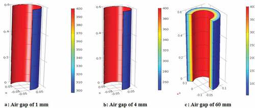
Figure 12. 3D Volume Plot depicting Heat flux in W.m-2 (Rainbow – Celsius scale) for different air gaps
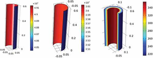
Simulations were also carried out to study the effect of thickness of the air gap between the Kanthal tubes and the refractory slots. The simulation results shown in ) indicate that as the thickness of the air gap increases, the heat flux dissipated from the inner to the outer cylinder in a concentric cylinders system decreases till a thickness of 100 mm. Thereafter, the heat flux from the Kanthal tubes to the outer cylinder is constant even if the thickness of the air gap is increased as the radiation effect decreases substantially after 100 mm gap. The optimum thickness of the air gap has been determined to be 3 mm from ) to facilitate the remote removal of Kanthal tube, as shown in .
Figure 13. (a) Total Energy Flux Vs Thickness of the air gap; (b) Change in temperature with time for different air gap thickness between refractories and Kanthal© tubes
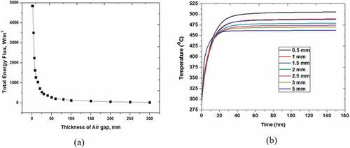
Figure 14. Prefabricated for placing of plenum heaters (a) circular slots; (b) Square slots
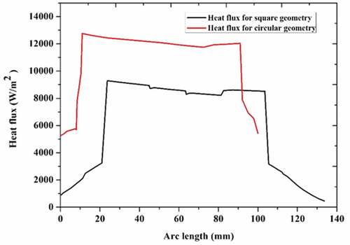
The heat flux across the diagonal section of the square slots was determined from simulation. This was then compared with the heat flux for a circular geometry. In this study, it was established that circular geometry results in increased heat flux as compared to square geometry, as shown in . The effect of geometry on the heating rate was studied using the validated model. The total heat flux of a circular geometry is 44% higher compared to square geometry. The area under the two curves will give power per unit length. The power per unit length for circular and square geometries are 1098.6 W/m and 813.6 W/m, respectively. These results reinforce the fact that circular slots provide better heat transfer rates. The results also show that by deploying circular geometry design in the prefabricated slots of the refractory, the heat flux, heating rate and thermal efficiency of the melter can be increased by 44%, 10.4%, and 35%, respectively. The average absolute relative error in the temperature estimated by the model is in the range of ± 12.5%.
Figure 15. Heat flux vs Distance in the prefabricated in the square and circular design0073
8. Conclusions
This work includes a numerical and experimental study of preheating refractories and a start-up technique for all-electric furnaces used in Nuclear Waste Management. Various parameters such as the gap between media and change in geometry of the slot were investigated. Based on the experiments carried out, energy apportionment during start-up was determined. It was observed that only 5% of the heat supplied to the system was utilized, raising the temperature of the glass frit.
A mathematical model that simulates the preheating of furnace is developed. The model incorporates all three modes of heat transfer. Numerical simulations of the validated model predicted that circular enclosures improve the heat flux by 44%. The simulations predicted the apportionment of different modes of heat transfer. Heat transfer by radiation was about 70% at an operating temperature of 700°C.
A numerical model was developed, and simulations were carried out using commercial multiphysics simulation software. Model predictions are compared with experimental results. The numerical model incorporates conjugate heat transfer effect. The model is validated with experimental results. The validated model was used for optimizing the air gap between the heating element and refractory. Different parameters that affect the efficiency of the start-up heating are identified, and the effect of these parameters on the efficiency of the start-up heating is quantified. The results obtained from these studies could be used for designing JHCMs used for vitrification of RLW.
Disclosure statement
No potential conflict of interest was reported by the authors.
References
- Suneel G, Satya Sai PM, Kaushik CP, et al. Experimental investigations and numerical modelling of Joule Heated Ceramic Melter for vitrification of radioactive waste. J Hazard Toxi Radioact Waste. 2018 Oct;23:1–14.
- Yoshioka M, Torata S, Igarashi H, et al. Glass melter and process development for PNC Tokai vitrification facility. Waste Manage. 2014;12:7–16.
- Chapman CC. Experience with a joule heated ceramic melter while converting simulated high-level waste to glass. Washington (USA): BNWL; 1976. ( (BNWL-SA-5762)).
- Weisenburger. S. Nuclear waste vitrification in a ceramic lined – lined electric glass melter. IEEE Trans Ind Appl. 1982 Jan;IA-18(1):73–82.
- Hardy BJ, Valachovic TG. CFD model for WSRC Am/Cm glass melter. South Carolina (USA): WSRC; 1998. ( (WSRC-MS-98-00106)).
- Erickson CJ, Haideri AQ. Electrical service and controls for Joule Heating of a nuclear waste experimental glass melter. IEEE Trans Ind Appl. 1985 Jul/Aug;1A-21(4):1070–1074.
- Saedodin S, Barforoush SMM. Comprehensive analytical study for convective-radiative continuously moving plates with multiple non-linearities. Energy Convers Manage. 2014;46:160–168.
- Shah JG. Characterization of matrices and vitrified waste products. Mumbai (India): Indian Nuclear Society News; 2008. (Report No. 5).
- Barforoush MSM, Saedodin S. Heat transfer reduction between two finite concentric cylinders using radiation shields: experimental and numerical studies. Int Commun Heat Mass Trans. 2015;65:94–102.
- Sharma AK, Veluswamy K, Balaji C, et al. Conjugate turbulent natural convection with surface radiation in air filled rectangular enclosures. Int J Heat Mass Trans. 2017;50:625–639.
- Teertstra P, Yovanovich MM. Comprehensive review of natural convection in horizontal circular annuli. Proceedings of 7th AIAA/ASME Joint Thermophysics and Heat Transfer Conference; 1998 Jun 15–18; Albuquerque, USA.
- Torabi M, Zhang Q. Analytical solution for evaluating the thermal performance and efficiency of convective-radiative straight fins with various profiles and considering all non-linearities. Energy Convers Manage. 2013;66:199–210.
- Malik AH, Shah A, Khushnood S. CFD analysis of heat transfer within a bottom heated vertical concentric cylindrical enclosure.Proceedings of 6th Vacuum and Surface Sciences Conference of Asia and Australia (VASSCAA-6); 2013 Oct 9–13; Islamabad, Pakistan.
- Kuznetsov VG, Sheremet AM. Conjugate natural convection in an enclosure with a heat source of constant heat transfer rate. Int J Heat Mass Trans. 2011;54:260–268.
- Malik AH, Alvi MS, Khushnood S, et al. Experimental study of conjugate heat transfer within a bottom heated vertical concentric enclosure. Int J Heat Mass Trans. 2012;55:1154–1163.
- Rahimi M, Sabernaeemi A. Experimental study of radiation and free convection in an enclosure with a radiant ceiling heating system. Energy Build. 2010;42:2077–2082.
- Narasimham GSVL, Senve V. Effective thermal conductivity of a heat generating rod bundle dissipating heat by natural convection and radiation. Nucl Eng Des. 2011;241:4331–4340.
- Roschina NA, Uvarov AV, Osipov AI. Natural convection in an annulus between coaxial horizontal cylinders with internal heat generation. Int J Heat Mass Trans. 2005;48:4518–4525.
- Pepper DW, Heinrich JC. The finite element method: basic concepts and applications. London (England): Taylor& Francis; 1992. p. 28–48.