
 ?Mathematical formulae have been encoded as MathML and are displayed in this HTML version using MathJax in order to improve their display. Uncheck the box to turn MathJax off. This feature requires Javascript. Click on a formula to zoom.
ABSTRACT
In this study, the flow and heat transfer of a double molten salt working fluid heat exchanger (DHX) in a high-temperature molten salt natural circulation experimental loop were investigated both experimentally and numerically. The experimental results demonstrated that the actual heat transfer of the DHX was superior, and the heat transfer coefficient of the DHX tube increased with the heating power. The simulation results agreed strongly with experimental data, proving that the proposed model was reasonable and feasible. The temperature and velocity distributions were obtained, and the flow flux distribution in the DHX tube was uniform. These results provide a reference for the design of a double molten salt heat exchanger in the passive decay-heat removal system of a fluoride salt-cooled high-temperature reactor.
1. Introduction
The fluoride salt-cooled high-temperature reactor (FHR) [Citation1] is a molten salt reactor design, which uses an advanced passive decay-heat removal system based on natural circulation. In a station blackout accident scenario, the passive decay-heat removal system can remove the core decay-heat to avoid excessive temperatures and ensure the reactor safety [Citation1]. However, the heat exchanger is the critical equipment in the passive decay-heat removal system for removing the decay-heat, and its heat transfer characteristics will affect the system capabilities.
International and domestic academics have carried out substantial research on the heat exchanger of the passive decay-heat removal system. The majority of existing studies on the heat exchanger have used water and other fluids for the water reactor and other reactors [Citation2–Citation11], and hardly any have used double molten fluids for the FHR [Citation12–Citation16]. For example, Ge [Citation4] performed a three-dimensional CFD simulation of the secondary side fluid flow and heat transfer of the passive residual heat removal heat exchanger (PRHR HX) in advanced passive safety pressurized water reactors (PWRs). Lu [Citation7] conducted an experimental investigation into the natural convection heat transfer characteristics of the C-shaped heating rods bundle used in the PRHR HX, which was immersed in an in-containment refueling water storage tank. Jiangbo [Citation10] constructed an experimental facility to investigate the heat removal capacity and stability characteristics of the steam generator secondary side passive heat removal system of a Chinese PWR, in which the working fluid was basically water. Wang [Citation12] studied the characteristics of the nitrate salt natural circulation loop, in which the working fluid was molten salt, but the research object was the nitrate salt natural circulation loop and not the heat exchanger.
Therefore, in this study, to gain further insight into the natural circulation characteristics of the heat exchanger with molten salt in the FHR, both an experiment and a simulation were conducted. A double molten salt working fluid heat exchanger (DHX) in a high-temperature molten nitrate salt natural circulation experimental loop (NNCL) built at the Shanghai Institute of Applied Physics, Chinese Academy of Sciences, was the research target. The velocity field and heat distribution in DHX and the tank were studied experimentally and numerically. The results may yield a good reference for the design of the DHX.
2. Experimental apparatus
2.1. Experimental system
A schematic of the NNCL is presented in , and the parameters of the main measuring instruments are displayed in . The NNCL employs HTS-1 (KNO3-NaNO2-NaNO3 (53-40-7 wt%)) as the coolants. It consists of a molten salt tank, a transport tank, an ultrasonic flow meter, a chimney, two heat exchangers (DHX and NDHX), an electric heater, several thermocouples, various pressure gauges, and a number of valves. The critical parameters are presented in . The heaters are made of wires, evenly jacketed on the outside surface of the molten salt tank to produce heat, which is the driving force of the NNCL, as with the heat from the reactor core. The maximum power of the heaters can reach 50 kW. An expansion tank is designed to be placed at the highest elevation of the natural circulation to allow for thermal expansion of the salt. The entire loop adopts superior-quality insulating cotton to provide excellent insulation effects and to reduce heat loss within the maximum limit.
Figure 1. Experimental system and apparatus for NNCL
Table 1. Parameters of main measuring instruments
Table 2. Parameters of NNCL
The salt in the molten salt tank is heated by the electric heater, and the heat is transferred from the molten salt tank to the loop by means of the DHX. As the salt in the DHX becomes hot, its density decreases, following which it rises and flows into the NDHX. After being cooled in the NDHX by the cold air flowing into the chimney, the salt density is increased, and then it flows down back to the DHX and natural circulation is formed. The mass flux and temperature in the experimental loop are precisely controlled by adjusting the electric heater power and supply air volume in the chimney.
The natural circulation is assumed to achieve a steady state when the salt temperatures in the salt tank and DHX remain nearly unchanged. A data acquisition and storage system is used to acquire and store the process operating data.
2.2. DHX
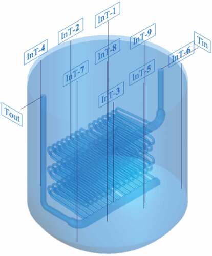
presents a diagram of the DHX and its measuring points, which has 30 Φ25 × 2.5 snake circular tubes. The length of each snake circular tube is 6 × 0.53 m, and the tubes are arranged according to a regular triangle. The material of the tubes is 316# stainless steel. The fluid temperature is measured by Φ3 mm NiCr-NiSi K-type thermocouples, which protrude into the DHX tube and salt tank. The insertion depths of thermocouples InT-1–3, InT-4–6, and InT-7–9 in the tank are 900, 1200, and 1600 mm, respectively. The thermocouple arrangements in the DHX and molten salt tank are also illustrated in .
Figure 2. DHX and measuring points
2.3 Data reduction
DHX was a tubular heat exchanger, and the heat transfer equations below used in this paper were appropriate [Citation17].
The heat transfer coefficient of the DHX inside tube is given by:
where the heat transfer flux Q is calculated as:
The qualitative temperature is
The inside-wall temperature of the DHX, Twi, can be obtained by
As the DHX is immersed in the molten salt, the outside wall temperature of the DHX can be approximately equal to that of the molten salt in the pool, that is: Two = Tt.
The average flow rate of the inlet fluid in the DHX inside-tube is:
2.4 Uncertainty analysis
presents the experimental uncertainties of the variables, which are dependent on the experimental conditions and measuring devices. The uncertainty of the wall heat flux is transferred from the uncertainties of the mass flow rate and fluid temperature. Moreover, the uncertainty of the heat transfer coefficient is transferred from the uncertainties of the heat flux, salt temperature in the DHX tube, and DHX inner wall temperature. The maximum uncertainty of the heat transfer coefficient between the tube wall and salt in the DHX was 33.8%, according to the method proposed by Moffat [Citation18].
Table 3. Uncertainties of variables
3 CFD simulation models
3.1 Meshing
In this study, the solid model was meshed using the ICEM mesher (of FLUENT Inc., USA). The geometry was meshed using unstructured tetrahedral elements, and the total number of computational cells was 1.26 × 10 [Citation6]. One important indicator of mesh quality that ANSYS ICEM allows to check is a quantity referred to as the orthogonal quality [Citation19]. In this paper, when the orthogonal quality was higher than 0.3, the simulation has a good convergence character. The typical computational domain and view of the computational grids are illustrated in .
Figure 3. Sectional view of computational grids

3.2 General setup
ANSYS Fluent version 14.5 was used to study the CFD simulation of the DHX. All of the cases were modeled as steady states. The Re numbers in this experiment were between 1300 and 3000 which is where a transition (from laminar to turbulent flow) regime typically occurs. And considering the k-ε model has better convergence character, it has been chosen in this paper.
The boundary conditions near the tank wall were calculated by the standard wall function. To solve the equations for the flow simulation, the SIMPLE algorithm was used for pressure and velocity coupling. The standard scheme was used for the pressure discretization, while the second-order upwind scheme was used for the momentum, turbulent kinetic energy, and dissipation rate discretization. Calculation convergence was assumed to be achieved when two conditions were attained: (1) when the residuals for the transport and energy equations decreased below 10−[Citation3] and 10−[Citation6], respectively, and (2) when the statistical average temperature at the DHX outlet remained constant.
The inlet boundary condition of the DHX was defined as the ‘“mass flow inlet”’, and the temperature and mass flow rate values of the salt at the DHX tube inlet were given. The turbulence intensity and hydraulic diameter were used for the turbulent simulations. The outlet boundary condition of the DHX was defined as the ‘“outflow”’. The wall thickness of the DHX was specified as 2.5 mm, and shell conduction was applied. And an energy source in the tank was defined.
4 Results and discussion
4.1 Experimental results
illustrates the experimental heat transfer coefficients in the DHX tube. The heat transfer coefficient of the DHX interior tube increased moderately with a heating power below 23 kW, and then increased rapidly when the heating power was over 23 kW. The heating power is the primary heat transfer source of the natural circulation loop. With an increase in the heating power, the DHX will gain additional heat from the salt tank, so the flow rate of the natural circulation and heat transfer coefficient will also increase.
There was a very strong increase in heat transfer at about 23 kW, the reason was the decrease in ambient temperature. Then, NDHX took more heat away from the loop, and the heat transfer capacity of the whole loop was stronger than the other condition, so the DHX took more heat away from the salt tank. And the temperature difference between the tank and the loop became smaller, then according to Equationequation (1)(1)
(1) , and the heat transfer coefficient of the DHX increased strongly too.
Figure 4. Experimental results of heat transfer coefficient
4.2 Numerical and experimental validation
illustrates the outlet temperatures of the DHX from the simulation and experiment. It is found that the orderliness of the simulation results is uniform with that of the experimental results.
The maximum error between the simulation and experimental results is approximately 3%, which is acceptable. This means the simulation result in this paper is reliable.
Figure 5. Comparison of experimental and numerical simulation results
The experimental and numerical simulation results of the thermocouples in the tank were shown in . The results showed that the thermocouple temperature at different height had little difference, which indicated there was a natural convection in the molten salt tank. The numerical simulation temperatures were higher than the experimental temperatures, for there was a heat dissipation loss of molten salt tank to the air.
Table 4. The experimental and numerical simulation results of the thermocouples in the tank
4.3 Numerical results
The simulation calculation mainly focused on the velocity and temperature distribution in the DHX tube. The following simulation results were obtained by using the experimental data as input, which were close to the design conditions.
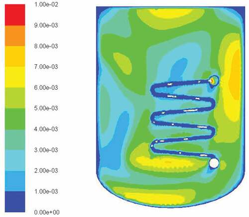
presents the velocity contour of the tank. It could seem the molten salt in the tank has a velocity, which showed that there was a natural convection in the tank.
Figure 6. Velocity contour of the tank
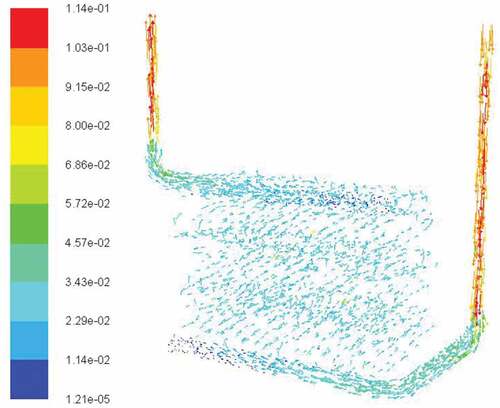
presents the velocity vectors of DHX. It can be noted that the velocity distribution of the little heat exchange tubes was uniform, which mean that DHX tubes were heated evenly. However, the velocity distribution of the mixing tube was not uniform, and the velocities at the ends of the mixing tubes were lower than in the other parts, which needed to be improved. The temperatures of inlet and outlet tubes were higher than the mixing tubes, as the inlet and outlet tube diameters were smaller than that of the mixing tube.
Figure 7. Velocity vectors of DHX
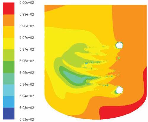
depicts the temperature distribution of the DHX. The inlet temperatures of the fluid in the DHX were lowest, and increased with the fluid flow as the fluid was heated. The coupling wall surface of the DHX heat exchanger was adopted for simulation, and the heat exchanger wall temperature increased gradually along with the fluid flow, which was consistent with the actual situation. The salt temperature in the DHX reached the outlet temperature early, demonstrating that the actual heat transfer between the fluid in the DHX and the wall was superior. The performance of the heat exchanger was better than required. depicts temperature distribution in the tank. It can be seen that the temperature in the tank had little difference, which indicated there was a natural convection.
Figure 8. Temperature distribution of DHX
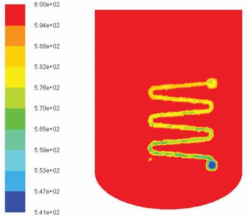
Figure 9. Temperature distribution in the tank
5 Conclusions
In the presented research, the performance of a DHX with double molten salt working fluid was investigated both experimentally and numerically. The numerical simulation was conducted using ANSYS Fluent 14.0, and the orderliness of the simulation results was uniform with that of the experimental results, that mean the simulation result in this paper was reliable. The experimental and simulation results provided the following conclusions:
The experimental results demonstrated that heat transfer coefficient of the DHX tube increases with the heating power.
According to the numerical simulation results, the temperature and velocity distributions were revealed, and the heat transfer and flow characteristics were studied. The Velocity magnitude distribution in the DHX tube was uniform. Velocity vector distribution showed that there was a natural convection in the tank. The temperature distribution also illustrated the fact performance of the heat exchanger was better than required.
Nomenclature
| A | = | The internal surface area of DHX, m2 |
| Ai | = | Cross-sectional area of the inlet port in DHX, m2 |
| cpm | = | Fluid-specific heat capacity in DHX, kJ/(kg·K) |
| d | = | Diameter of inlet port in DHX, m |
| qm | = | Average mass of fluid in DHX, kg/h |
| qv | = | Volume flow rate of fluid in DHX, m3/h |
| T1 | = | Inlet temperature of fluid in DHX, K |
| T2 | = | Outlet temperature of fluid in DHX, K |
| Two | = | Outside wall temperature of DHX, K |
| Twi | = | Inside wall temperature of DHX, K |
| Tt | = | Temperature of molten salt in tank, K |
| ρm | = | Fluid density in DHX, kg/m3 |
| λm | = | Fluid thermal conductivity in DHX, W/(m K) |
| λw | = | Thermal conductivity of DHX wall, W/(m K) |
| δ | = | Wall thickness of DHX, m |
| µm | = | Fluid dynamic viscosity in DHX, kgs/(m2) |
| Non-dimensional numbers | = | |
| Nu | = | Nusselt number |
| Pr | = | Prandtl number |
| Re | = | Reynolds number |
Disclosure statement
No potential conflict of interest was reported by the authors.
Additional information
Funding
References
- Forsberg C, Hu L, Peterson PF, et al. Fluoride salt- cooled High-temperature reactors (FHRs) for base-load and peak electricity, grid stabilization, and process heat. America: Massachusetts Institute of Technology, University of California at Berkeley, and University of Wisconsin; 2013.
- Chen BD, Xiao ZJ, Zhou RM. Test facility and research program of AC600 secondary-side passive emergency core residual heat removal system. Nucl Power Eng. 1988;19:97–101. in Chinese
- Chen BD, Xiao ZJ, Zhuo WB. The heat removal study of AC600 passive system. J Eng Thermophys. 1999;20:17–21. in Chinese
- Jian G, Tian W, Qiu S, et al. CFD simulation of secondary side fluid flow and heat transfer of the passive residual heat removal heat exchanger. Nucl Eng Des. 2018;337:27–37.
- Tao J, Gu H, Xiong Z, et al. Parametric analysis of heat transfer rate of passive residual heat removal heat exchanger submerged in water tank. Exp Therm Fluid Sci. 2018;98:317–327.
- Yonomoto T, Kukita Y, Schultz RR. Heat transfer analysis of the passive residual heat removal system in ROSA/AP600 experiments. Nucl Technol. 1998;124:18–30.
- Lu DG, Zhang YH, Fu XL, et al. Experimental investigation on natural convection heat transfer characteristics of C-shape heating rods bundle used in PRHR HX. Ann Nucl Energy. 2016;98:226–238.
- Chun MH, Kang MG. Effects of heat exchanger tube geometries on nucleate pool boiling heat transfer in a scaled in-containment refueling water storage tank. Int Commun Heat Mass. 1996;23:23–34.
- Wright RF, Schwall JR, Karim NU, et al., AP1000 passive residual heat removal heat exchanger confirmatory analysis. Proceedings of the 14nd International Conference on Nuclear Engineering. 2006:567–557
- Wu JB, Bi QC, Zhou CS. Experimental study on circulation characteristics of secondary passive heat removal system for Chinese pressurized water reactor. Appl Therm Eng. 2015;77:106–112.
- Xiao ZJ, Qiu SZ, Zhuo WB. The development and verification of thermalhydraulic code on passive residual heat removal system of Chinese advanced PWR. Nucl Sci Tech. 2006;17:301–307.
- WANG K, Chuangxiong CAI, Zhaozhong HE, et al. Characteristics analysis of the nitrate salt natural circulation loop. Nucl Tech. 2015;38:040602.
- Chuangxiong CAI, Zhaozhong HE, Kun CHEN Preliminary model validation for integral stability behavior in molten salt natural circulation. Proceedings of ICAPP 2017 Fukui and Kyoto (Japan). 2017
- Lv Q, Lin HC, Kim IH, et al. DRACS thermal performance evaluation for FHR. Ann Nucl Energy. 2015;77:115–128.
- Hughes JT, Edward D. Blandford, experimental investigation of a directionally enhanced DHX concept for high temperature direct reactor auxiliary cooling systems. Nucl Eng Des. 2016;303:132–152.
- Kudariyawar JY, Srivatsav AK, Vaidya AM, et al. Computational and experimental investigation of steady state and transient characteristics of molten salt natural circulation loop. Appl Therm Eng. 2016;99:560–571.
- Incropera FP, David P, Witt D, et al. Fundamentals of heat and mass transfer 2007 J[B]. Hoboken (NJ): Wiley & Sons. 2011;212–213.
- Moffat RJ. Describing the uncertainties in experimental results. Exp Thermal Fluid Sci. 1988;1:3–17.
- ANSYS ICEM CFD 11.0 Tutorial Manal.