
 ?Mathematical formulae have been encoded as MathML and are displayed in this HTML version using MathJax in order to improve their display. Uncheck the box to turn MathJax off. This feature requires Javascript. Click on a formula to zoom.
ABSTRACT
In this paper, to clarify the conditions for the occurrence of macroscopic hydrogen-induced ductile-to-brittle transitions (DBT) at operational temperatures, the effect of hydride precipitation on the mechanical properties of fuel cladding at 300°C was investigated. Tube burst tests were performed on the high-burnup Zr-lined Zircaloy-2 fuel cladding samples that were subjected to a hydrogen charging and hydride reorientation treatment. The precipitated hydrides had no significant effect on the cladding strength until the cladding lost its plasticity. Circumferential permanent strains at failure tended to decrease as the hydrides became longer, more densely precipitated, and more aligned to the radial direction. These results confirm that cladding ductility can be reduced significantly by hydrogen absorption even at 300°C if an extent of radial hydride formation is sufficiently high. Further, observations suggest that approximately 1% of the circumferential strain serves as a threshold for identifying the macroscopic hydrogen-induced DBT of the Zircaloy-2 cladding.
1. Introduction
Zirconium alloys are used extensively as the material for nuclear fuel cladding in light water reactors, mainly due to their good corrosion resistance and low thermal neutron-absorption cross section. Since the fuel cladding acts as a physical barrier to prevent a release of radioactive materials, it is important to ensure the cladding integrity over an entire life. An over-power transient during a reactor service can cause fuel pellets to expand, inducing a tensile load on the cladding. To avoid failure due to over-strain, the cladding must retain a certain degree of ductility even in the face of any degradation of mechanical properties that could occur during the reactor operation.
Zirconium alloys are known to pick up hydrogen that is generated mainly by corrosion of the cladding surface during operation [Citation1]. If the hydrogen content reaches the terminal solid solubility of hydrogen (TSS) in Zr alloys, hydrogen precipitates as brittle zirconium hydrides. Significant precipitation of these hydrides is likely to degrade the mechanical properties of the Zr alloy cladding. Since this phenomenon is related closely to the integrity of the fuel cladding, hydrogen-induced embrittlement of Zr alloy materials has been studied extensively. Many researchers [Citation2–Citation12] reported that the strain of the specimens at failure tends to decrease as the hydrogen content increases and can be reduced to zero at room temperature if the hydrogen content reaches a critical value. However, at elevated temperatures, such as 300°C, which is close to the fuel cladding temperature during reactor operation for a boiling water reactor (BWR), hydrogen-induced embrittlement turns to be insignificant, and specimens recovered ductility despite a high hydrogen content [Citation2–Citation5,Citation7–Citation11]. Kim et al. [Citation11] performed ring compression tests on cold-worked, stress-relieved Zircaloy-4 cladding specimens in the temperature range of 25°C-300°C. They found that the specimens with the hydrogen content of approximately 830 ppm (mg/kg) recovered ductility at temperatures higher than 150°C. While the macroscopic fracture behavior of hydrided specimens is recognized as ductile in these studies, Hsu et al. [Citation10] found a brittle feature, namely the quasi-cleavage of Zr hydrides, on the fracture surface of a recrystallized Zircaloy-4 cladding sample that was subjected to mechanical testing at 300°C. Arsene et al. [Citation6] conducted ring tensile tests at 300°C on hydrided Zircaloy cladding and reported that the reduction of area of the recrystallized Zircaloy sample containing 3000 ppm of H was nearly zero.
Along with its hydrogen content, the hydride morphology has a critical effect on the ductility of Zr alloy cladding [Citation5,Citation9,Citation11,Citation13–Citation15] and ductility can be reduced significantly if the hydride platelets’ normal is parallel to the axis of the tensile stress. Moreover, assuming that hydrides could be crack paths, longer hydride platelets are considered to be more detrimental to the tensile properties. Kim et al. [Citation11] showed that ductility of the cladding specimens with radial hydrides significantly reduced at 150°C despite the hydrogen content being as low as 150 ppm. Further, Arsene et al. [Citation6] claimed that the fracture surface of the sample was completely of a brittle nature and the observed DBT seemed to be due to an increase in the number of radial hydrides following an increase in hydrogen content. These findings indicate that Zr hydride is brittle even at higher temperatures, though it shows some plasticity in a strict sense [Citation16], and that the cladding’s macroscopic ductility can be reduced significantly if the extent of radial hydride formation is sufficiently high.
This study aims to clarify the condition for the occurrence of macroscopic hydrogen-induced DBT at operational temperatures because it is important to evaluate the safety margin in an over-power transient. Thus, the effect of hydride precipitation on the fuel cladding mechanical properties at 300°C has been further investigated by performing tube burst tests and post-test analyses on the high-burnup Zr-lined Zircaloy-2 fuel cladding samples.
2. Methods
2.1. Sample preparation
High-burnup spent fuel rods were defueled and cut into 45-mm-long Zr-lined Zircaloy-2 cladding tube samples for the tube burst tests. The mother rods were taken from two BWR fuel assemblies irradiated in a commercial reactor for five cycles. The Bundle average burnups of the assemblies were 47.9 GWd/t and 53.0 GWd/t. The local burnups and fast neutron fluences of the tube samples were in the ranges of 52.5–68.8 GWd/t and 8.1–13.2 × 1025 m−2 (E > 1MeV), respectively. lists the properties of these tube samples.
Table 1. Test samples
The samples were charged further with hydrogen by heating them to 290°C for up to 21 days in an aqueous solution of 1 mol/L lithium hydroxide. During this hydrogen-charging process, hoop stress of 150 MPa was applied to the tubes with internal gas pressure to increase hydrides precipitation in radial direction; this process is referred to as hydrogen charging and hydride reorientation treatment (HCRT) below. We considered 150 MPa to be sufficient hoop stress for the hydride reorientation based on previous studies. Stehle et al. [Citation17] and Aomi et al. [Citation12] reported that the reorientation of hydrides into a radial direction became clear when the applied hoop stress exceeded approximately 110 MPa.
Irradiation-induced defects that are known to lead to material hardening [Citation18,Citation19] can be recovered by thermal annealing at elevated temperature [Citation18,Citation20,Citation21]. Nevertheless, according to data reported by Hirose et al. [Citation22], either annealing at 270°C for 5000 h or 300°C for 1000 h had a negligible effect on the hardness of the irradiated cladding samples with burnups of approximately 60 GWd/t. Therefore, in this study, changes in the mechanical properties of the samples due to the recovery of irradiation damage during HCRT can be ignored.
shows the typical transverse micrographs of the HCRT-subjected samples. The orientations of the hydrides in the as-irradiated samples are relatively random. The length and number of radial hydrides appear to increase as the period of HCRT increases. The hydrogen content of each sample was measured by the inert-gas fusion thermal-conductivity detection method. For these measurements, small rings were taken from each sample after the tube burst tests described below. Because a large amount of hydrogen was accumulated in the Zr liner region (), particularly in the HCRT-subjected samples, we also conducted hydrogen content measurements on the rings from which the Zr liner was removed by mechanical grinding. summarizes the results of these measurements. The hydrogen contents of the bulk rings (referred to as CH bulk) and the rings after removal of the Zr liner (referred to as CH liner removed) were in the ranges of 120–1515 and 67–343 ppm, respectively. The latter corresponds to the hydrogen content in the Zircaloy-2 region of the cladding.
Table 2. Hydrogen contents and values of Flθ/A for the samples along with the UTS and circumferential permanent strains to failure obtained from the tube burst tests described in Section 2.3
Figure 1. Transverse metallographs of (a) KY87 (as irradiated), (b) KY90 (HCRT-3 days), (c) KY94 (HCRT-9 days), and (d) KY92 (HCRT-21 days). The cross sections of each sample were etched with a solution of HF, HNO3 and H2O2 in a volume ratio of 0.8:3.0:40.0
During HCRT, the outer surface of the sample corroded; consequently, the oxide layer became thicker. Accordingly, the thickness of the metal portion of the cladding sample decreased, increasing the hoop stress applied to the sample during the tube burst test described in 2.3. In comparison with the sample subjected to HCRT for 21 days and the as-irradiated sample, the thickness of the oxide layer increased by approximately 20 μm. Assuming that the Pilling Bedworth ratio of zirconium (1.56) applies to Zircaloy-2, the increase of the hoop stress is calculated to be approximately 2%; therefore, surface corrosion due to HCRT has little effect on an evaluation of circumferential strength in this study.
2.2. A quantitative parameter to characterize hydride morphology
As previously described, hydride morphology has a critical effect on the ductility of zirconium alloy cladding [Citation5,Citation9,Citation11,Citation13–Citation15] and ductility can be affected by the extent of radial hydride formation. Moreover, assuming that hydrides could be crack paths, longer hydride platelets are considered to be more detrimental to the tensile properties. Since the hydrogen content alone gives no information related to the orientations or lengths of the hydrides, different parameters have been proposed in previous studies [Citation13,Citation23–Citation25] and defined in standards [Citation26,Citation27] to characterize the hydride morphology and its impact on the cladding ductility. Considering that the radial component of hydrides is essential for the ductility of the cladding under the pellet-cladding mechanical interaction conditions, the authors propose the following parameter expressed as EquationEquation (1)(1)
(1) . The variables in this equation are extracted from image analysis of transverse micrographs of the samples.
where li is the length of the hydride, θi is the angle between the hydrides and radial axis, and A is the area of a rectangular domain in the Zircaloy-2 region subjected to the image analysis (). First, a transverse micrograph was turned into a binary image for discriminating the metal and hydrides; then, each hydride was vectorized to obtain its length and angle. In this study, hydrides less than 16-μm-long were ignored, and connected hydrides with an angle of greater than 13 degrees were treated as separate hydrides in accordance with ASTM B811-02 [Citation26], JIS H4751:2016(E) [Citation27] and previous studies [Citation13,Citation25]. The image analysis was performed in intervals of 90 degrees on each sample. The shown values of Flθ/A are the average of the four calculations. The numerator in EquationEquation (1)(1)
(1) corresponds to the sum of the lengths of the projections of hydrides in the radial direction. Therefore, the orientations, lengths, and frequencies of the appearance of the hydrides precipitated in a sample are taken into account in Flθ/A. The values of Flθ/A increase as the period of HCRT increases, as summarized in . Preexisting and absorbed hydrogen in a solid solution precipitated in the radial direction due to the circumferential tensile stress applied during HCRT.
Figure 2. Schematic of the image analysis for obtaining length and radial orientation of each hydride. The rectangular target domain does not include the Zr liner region nor the interface between the Zr liner and Zircaloy-2 region
2.3. Tube burst test
Open-end tube burst test was performed to investigate the circumferential tensile properties of the samples, and illustrates the test device. A uniaxial tensile load was applied to the samples at 300°C via internal pressure generated from silicone oil. The circumferential stress was increased at the rate of 3 MPa/s. The outer diameter of the sample at its longitudinal center was measured on-line during the test using a laser device. We terminated pressurization when a rapid pressure drop occurred, as this pressure drop indicates a failure of the sample. Then, the sample was cooled down to room temperature at approximately 1°C/s and the maximum outer diameter and width of the burst opening were measured to calculate the permanent strain to failure. Optical microscope (OM) observations of cross sections at the middle of the burst opening were performed on each sample, and several samples were subjected to scanning electron microscope (SEM) fractography.
Figure 3. Schematic of the tube-burst test device
3. Results and discussion
3.1. Hydrides’ effect on cladding strength
shows the circumferential stress-strain curves that were obtained from the tube burst tests. The stress values were calculated based on the internal pressure measured during each test, and the circumferential strain values were calculated as the proportion between a diameter increment at longitudinal center measured during the test and an initial diameter of a sample. The as-irradiated samples and samples subjected to HCRT for shorter periods generally exhibited higher strain. However, the samples subjected to HCRT for longer periods and contained more radial hydrides exhibited very low strain. and summarize the ultimate tensile strength (UTS) and Flθ/A for each sample.
Figure 4. Circumferential stress-strain curves obtained from the tube burst tests. The circumferential strains displayed were calculated as diameter increments at the longitudinal center of the samples during the test, and this calculation differs from that of the circumferential permanent strains to failure displayed in
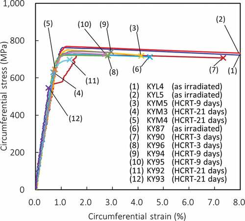
Figure 5. Circumferential UTS against Flθ/A
Hydrogen in a solid solution may affect the strength of zirconium alloys, as reported previously. For example, Kim et al. found that hydrogen has a strengthening effect [Citation28]. They claimed that hydrogen dissolved into the zirconium matrix leads to solute hardening. On the contrary, Yamanaka et al. showed a softening effect due to a decrease of the Zr-Zr bond by interstitial hydrogen solution [Citation29]. The TSS of hydrogen for Zircaloy-2 at 300°C is reported to be approximately 60 ppm [Citation30,Citation31]. Since the CH liner removed of the samples used in this study are higher than or approximately equal to TSS at 300°C, the amount of hydrogen dissolved into the Zr matrix are saturated in all the samples. Therefore, the influence of hydrogen in the solid solution is negligible for the samples used in this study.
In , regarding the samples subjected to HCRT for less than or equal to 9 days which contained fewer radial hydrides and showed higher strain, no obvious difference in UTS are seen among the samples, namely, the corresponding variations in the hydrogen content (CH liner removed = 67–222 ppm) and hydride morphology (Flθ/A < 25 mm/mm2) have no significant effect on the circumferential strength. This result coincides with the information mentioned above.
The UTS values of the samples KYM3, KYM4, KY92, and KY93 which were subjected to HCRT for 21 days (CH liner removed = 315–343 ppm, Flθ/A = 29.4–52.1) are relatively low. Such a reduction in the strength at elevated temperatures has not been reported for cladding samples that have similar hydrogen contents but do not have remarkable extents of precipitation of the radial hydrides [Citation2,Citation5–Citation7,Citation11]. shows that these four samples failed before yield or just after yield, resulting in low UTS values. These results suggest that an increase in the amount of radial hydrides affects the cladding ductility rather than strength, and agrees with previous results [Citation6,Citation11]. The details of the changes in fracture behavior in terms of ductility are discussed in the next section.
Consequently, precipitated hydrides were confirmed to have no significant effect on the cladding strength at operational temperatures until the cladding loses its plasticity regardless of the presence of radial hydrides.
3.2. Fracture behavior and the effect of HCRT on ductility
and summarize the circumferential permanent strains to failure and Flθ/A for each sample. Circumferential permanent strains to failure tend to decrease with increasing Flθ/A. Ductility of the cladding is generally decreased by neutron irradiation and hydrogen absorption [Citation2–Citation4,Citation25,Citation32,Citation33]. The decrease due to neutron irradiation is significant during the shorter period (< ~1 × 1025 m−2), and the decrease rate gradually reduces at higher fluences [Citation25,Citation32]. Since the variation of the neutron fluence is small among the examined cladding samples, the trend in the figure is caused by hydrogen absorption or the combined effects of irradiation and hydrogen absorption.
Figure 6. Permanent circumferential strain to failure against Flθ/A
The ductility of the irradiated cladding has been reported to scatter to some extent in the measurement using the burst test with similar lengths of the cladding [Citation12,Citation25,Citation32,Citation34]. Thus, the lower bound of the data is focused in the present study from the reactor safety viewpoint. The minimum value of circumferential permanent strain to failure of the as-irradiated samples is 7.5%, which decreases with increasing Flθ/A. The samples subjected to HCRT for 21 days exhibit less than 1% of the circumferential permanent strain to failure.
shows the appearances of some of the samples after testing. The stripes that correspond to the formation of shear bands are observed on the surfaces of both the as-irradiated samples and the samples subjected to HCRT for less than or equal to 9 days. The cracks in these samples are observed in the shear bands tilted at 45° in the axial circumferential plain. Such localized deformation was previously observed in irradiated Zircaloy cladding tested between approximately 600 and 700 K, and the deformation is caused by dislocation channeling [Citation4,Citation35,Citation36]. Axial cracks also appeared in the samples that were subjected to HCRT for 9 days. No stripes are observed on the surface of the samples subjected to HCRT for 21 days and those samples have axial cracks which have propagated over the entire length.
Figure 7. Post-test photographs of (a) KY87 (as irradiated), (b) KY90 (HCRT-3 days), (c) KY94 (HCRT-9 days), and (d) KY92 (HCRT-21 days). Percentages in the lower right of each image indicate the circumferential permanent strain to failure
Post-test transverse micrographs and SEM fractographs of the samples subjected to HCRT for 9 days or less are shown in and , respectively. In samples KY87 and KY90, large decreases in thickness (,) and dimples on the fracture surfaces (,) appeared, confirming that these samples remained ductile. On the other hand, the decrease in the thickness of sample KY94 is not remarkable (). However, ) shows that the sample was shear-fractured with cracking along the 45° direction to the tensile stress, which is often observed in a fracture of a ductile metal. Furthermore, dimples were observed in the Zircaloy-2 region on the fracture surface (). Therefore, it is considered that some ductility remained in the sample KY94.
Figure 8. Post-test transverse metallographs of (a) KY87 (as irradiated), (b) KY90 (HCRT-3 days), and (c) KY94 (HCRT-9 days). Percentages in the lower right of each image indicate the circumferential permanent strain to failure
Figure 9. SEM fractographs of (a) KY87 (as irradiated), (b) KY90 (HCRT-3 days), and (c) KY94 (HCRT-9 days). Percentages in the lower right of each image indicate the circumferential permanent strain to failure
A brittle feature, e.g., the quasi-cleavage of the hydrides, is observed on the fracture surface of the Zr liner region of KY94 (c2)) indicating that its plastic deformation (equivalent to 4.5% of the circumferential permanent strain to failure) depends only on the remaining ductility of the Zircaloy-2 region, and not the Zr liner region.
and show the post-test transverse micrographs and SEM fractographs of the samples subjected to HCRT for 21 days. ,) show that the cracks in samples KY93 and KYM3 propagated along the radial hydrides over almost the entire sample thickness. This behavior is consistent with the quasi-cleavages of the hydrides observed over the entire region of the fracture surfaces of these two samples (). Although we did not perform SEM fractography on samples KY92 and KYM4, from a comparison of the post-test transverse micrographs (), the cracks in these samples appear to propagate in the same manner as those of KY93 and KYM3. From these results, we conclude that all the samples subjected HCRT for 21 days failed in a brittle manner at 300°C because of the increased extent of the radial hydride formation.
Figure 10. Post-test transverse metallographs of the samples subjected to HCRT for 21 days; (a) KY92, (b) KY93, (c) KYM3, and (d) KYM4. Percentages in the lower right of each image indicate circumferential permanent strain to failure
Figure 11. SEM fractographs of the samples subjected to HCRT for 21 days; (a) KY93 and (b) KYM3. Percentages in the lower right of each image indicate the circumferential permanent strain to failure
The circumferential stress-strain curve for KY92 () shows that the sample yielded before failure. In other words, the sample deformed plastically. However, this plastic deformation was quite limited, and the sample failed in a brittle manner as seen in ). These observations suggest that KY92 can be treated as a boundary case for macroscopic DBT of the cladding. Since the circumferential permanent strain to failure of KY92 is 0.9%, approximately 1% of circumferential strain likely serves as a threshold for identifying the macroscopic DBT at 300°C. The Flθ/A value corresponding to 1% of the circumferential permanent strain to failure is approximately 29 mm/mm2 for this study.
3.3. Effect of hydride morphology on cladding ductility
In this section, we discuss KY94 and KY92 to study the effects of the morphology of the hydrides on ductility because these two samples contain the same level of hydrogen but were subjected to HCRT for different periods.
The values of CH liner removed for KY94 and KY92 were 204 ppm and 213 ppm, respectively. CH liner removed is used as an indicator of hydrogen content here because, as mentioned above, the plastic deformation of the samples should depend on the remaining ductility of the Zircaloy-2 region though a much larger amount of hydrogen that tends to accumulate at the Zr liner region. Hydrogen measurements were performed at room temperature after tube burst testing at 300°C. The temperature distribution along the sample thickness is considered to be homogeneous during the test, so the diffusion of hydrogen from the liner to the Zircaloy-2 regions is negligible. Hence, it is reasonable that no difference exists between CH liner removed at room and testing temperatures.
The circumferential permanent strains to failure of KY94 and KY92 were 4.5% and 0.9%, respectively. This remarkable difference, despite the same level of CH liner removed, is explained by the difference in the morphology of the hydrides. The values of Flθ/A indicate that longer and a greater number of hydrides are oriented toward the radial direction in KY92 (Flθ/A = 29.4 mm/mm2) compared with KY94 (Flθ/A = 20.2 mm/mm2).
These findings confirm that the cladding ductility can be reduced significantly by hydrogen absorption, even at 300°C, if an extent of precipitation of radial hydrides is sufficiently high. In this study, the critical value for macroscopic DBT on the extent of radial hydride precipitation was successfully identified by using one parameter that quantitatively characterizes the hydride morphology.
4. Conclusion
To clarify the condition for the occurrence of macroscopic hydrogen-induced DBT at operational temperatures for nuclear power reactors, the effect of hydride precipitation on the fuel cladding mechanical properties at 300°C was investigated. Tube-burst tests and post-test analyses were performed on the high-burnup Zr-lined Zircaloy-2 fuel cladding samples subjected to hydrogen charging and hydride reorientation treatment. The main conclusions include:
The precipitated hydrides have no significant effect on cladding strength at reactor operating temperatures until the cladding loses its plasticity. Circumferential permanent strains to failure showed a trend to decrease with increasing Flθ/A, as this parameter quantitatively characterizes the morphology of hydrides in terms of length, orientation, and density. Accordingly, an increase of hydrides having the radial components decreases the ductility of the zirconium alloy cladding even at high temperatures.
Post-test OM observations and SEM fractography revealed that all the samples with high Flθ/A (high hydrogen content and increased radial hydrides) failed in a brittle manner at 300°C. The circumferential permanent strains to failure of these samples were below 1%. Accordingly, approximately 1% of the circumferential strain likely serves as a threshold for identifying the macroscopic ductile–brittle transition in cladding failure behavior at operational temperatures. For the sample tested in this study, the value of Flθ/A corresponding to 1% of the circumferential permanent strain to failure is approximately 29 mm/mm2.
Acknowledgments
The authors gratefully acknowledge M. Aomi at Global Nuclear Fuel-Japan and Y. Etoh at Nippon Nuclear Fuel Development for performing the tests necessary for our research.
Disclosure statement
No potential conflict of interest was reported by the authors.
References
- Corrosion of zirconium alloys in nuclear power plants. Austria: IAEA; 1993. IAEA-TECDOC-684.
- Hermann A, Martin M, Poerschke P, et al. Ductility degradation of irradiated fuel cladding. Vol. IV. Switzerland: Paul Scherrer Institute; 2001, Paul Scherrer Institute Scientific Report; 2000.
- Uchida M, Ichikawa M. Effect of pre-hydriding on post-irradiation ping-tensile properties of Zirclaoy-2 cladding tube. J Nucl Sci Technol. 1976;13:585–590.
- Garde AM Effects of irradiation and hydriding on the mechanical properties of Zircaloy-4 at high fluences. Proc. Zirconium in the nuclear industry: Eith International Symposium, ASTM STP 1023; 1988 Jun; San Diego (United States).
- Bai JB, Prioul C, François D. Hydride embrittlement in Zircaloy-4 plate: part I. Influence of microstructure on the hydride embrittlement in Zircaloy-4 at 20 °C and 350 °C. Metall Mater Trans A. 1994;25:1185–1197.
- Arsene S, Bai JB, Bompard P. Hydride embrittlement and irradiation effects on the hoop mechanical properties of PWR and BWR Zircaloy cladding tubes part 1. Metall Mater Trans A. 2003;34A:553–566.
- Yagnik SK, Kuo R-C, Rashid YR, et al. Effect of hydrides on the mechanical properties of Zircaloy-4. Proc.: 2004 International Meeting on LWR Fuel Performance; 2004 Sep 19–22; Orlando (United States).
- Daum RS, Majumdar S, Liu Y, et al. Radial-hydride embrittlement of high-burnup Zircaloy-4 fuel cladding. J Nucl Sci Technol. 2006;43:1054–1067.
- Billone MC, Burtseva TA, Einziger R. Ductile-to-brittle transition temperature for high-burnup cladding alloys exposed to simulated drying-storage conditions. J Nucl Mater. 2013;433:431–448.
- Hsu H-H, Chiang M-F, Chen Y-C. The influence of hydride on fracture toughness of recrystallized Zircaloy-4 cladding. J Nucl Mater. 2014;447:56–62.
- Kim J-S, Kim T-H, Kook D-H, et al. Effects of hydride morphology on the embrittlement of Zircaloy-4 cladding. J Nucl Mater. 2015;456:235–245.
- Ogata K, Baba T, Kamimura K, et al. Effect of increased hydrogen content on the mechanical performance of irradiated cladding tubes. Proc. Top Fuel 2012; 2012 Sep 2–6; Manchester (United Kingdom).
- Aomi M, Baba T, Miyashita T, et al. Evaluation of hydride reorientation behavior and mechanical properties for high-burnup fuel-cladding tubes in interim dry storage. Proc. 15th International Symposium on Zirconium in the Nuclear Industry, ASTM STP 1505; 2007 Jun 24–28; Sunriver (United States).
- Louthan MR, Marshall RP. Control of hydride orientation in Zircaloy. J Nucl Mater. 1963;9:170–184.
- Marshall RP. Influence of fabrication history on stress-oriented hydrides in Zircaloy tubing. J Nucl Mater. 1967;24:34–48.
- Barraclough KG, Beevers CJ. Some observations on the deformation characteristics of bulk polycrystalline zirconium hydride part 1. The deformation and fracture of hydrides based on the delta-phase. J Mater Sci. 1969;4:518–525.
- Stehle H, Kaden W, Manzel R. External corrosion of cladding in PWRs. Nucl Eng Des. 1975;33:155–169.
- Howe LM, Thomas WR. The effect of neutron irradiation on the tensile properties of zircaloy-2. J Nucl Mater. 1960;2:248–260.
- Higgy HR, Hammad FH. Effect of neutron irradiation on the tensile properties of Zircaloy-2 and Zircaloy-4. J Nucl Mater. 1972;44:215–227.
- Torimaru T, Yasuda T, Nakatsuka M. Changes in mechanical properties of irradiated Zircaloy-2 fuel cladding due to short term annealing. J Nucl Mater. 1996;238:169–174.
- Ito K, Kamimura K, Tsukuda Y. Evaluation of irradiation effect on spent fuel cladding creep properties. Proc. 2004 International Meeting on LWR Fuel Performance; 2004 Sep 19–22; Orlando; United States.
- Hirose T, Ozawa M, Miura H, et al. 2013: Research on integrity of high burnup spent fuel under long term dry storage and transport. France: OECD/NEA/CSNI, NEA: CSNI/R; 2013. 10.
- Raynaud PA, Koss DA, Motta AT. Crack growth in the through-thickness direction of hydrided thin-wall zircaloy sheet. J Nucl Mater. 2012 Jan;420:69–82.
- Wallace AC, Shek GK, Lepik OE. Effects of hydride morphology on Zr-2.5Nb fracture toughness. Proc.: Zirconium in the nuclear industry: Eith International Symposium, ASTM STP 1023; 1988 Jun; San Diego (United States).
- Ogata K, Aomi M, Baba T, et al. Progress in the research programs to elucidate axial cracking fuel failure at high burnup. Proc.: 2007 International LWR Fuel Performance Meeting; 2007 Sep; San Francisco (United States).
- ASTM B811-02. Standard Specification for Wrought Zirconium Alloy Seamless Tubes for Nuclear Reactor Fuel Cladding, American Society for Testing and Materials International; 2007.
- JIS H 4751:2016(E). Zirconium alloy tubes. Japanese Standards Association.
- Kim JH, Lee MH, Choi BK, et al. Effect of the hydrogen contents on the circumferential mechanical properties of zirconium alloy claddings. J Alloys Compd. 2007;431:155–161.
- Yamanaka S, Setoyama D, Muta H, et al. Characteristics of zirconium hydrogen solid solution. J Alloy Compd. 2004 Jun;372:129–135.
- Une K, Ishimoto S. Dissolution and precipitation behavior of hydrides in Zircaloy-2 and high Fe Zircaloy. J Nucl Mater. 2003;322:66–72.
- Une K, Ishimoto S, Etoh Y, et al. The terminal solid solubility of hydrogen in irradiated Zircaloy-2 and microscopic modeling of hydride behavior. J Nucl Mater. 2009;389:127–136.
- Mishima Y, Okubo T, Ohishi M, et al. Proving test on reliability for BWR fuel assembies. J Atom Energ Soc Jpn. 1987 Feb;29:90–115.
- Miyashita T, Nakae N, Ogata K, et al. Verification program of BWR 9 × 9 fuel. Trans Atomic Energy Soc Jpn. 2008 Dec;7:380–395.
- Mishima Y. Cooperative study for standardization of testing procedures for Zircaloy cladding tubes for BWR, using domestically manufactured ones. J Atom Energ Soc Jpn. 1974 Jun;16:306–311.
- Lee D, Adamson RB Modeling of localized deformation in neutron irradiated zircaloy-2. Proc.: 3rd International Conference on Zirconium in the Nuclear Industry, ASTM STP 633; 1976 Aug 10–12; Quebec (Canada).
- Yasuda T, Nakatsuka M, Yamahsita K Deformation and fracture properties of neutron-irradiated recrystallized zircaloy-2 cladding under uniaxial tension. Proc.: 7th International Symposium on Zirconium in the Nuclear Industry, ASTM STP 939; 1985 Jun 24–27; Strasbourg (France).