
 ?Mathematical formulae have been encoded as MathML and are displayed in this HTML version using MathJax in order to improve their display. Uncheck the box to turn MathJax off. This feature requires Javascript. Click on a formula to zoom.
ABSTRACT
Key phenomena in the cooling states of underwater debris beds were classified based on the premise that a target debris bed has a complicated geometry, nonhomogeneous porosity, and volumetric heat. These configurations may change due to the molten jet breakup, droplet agglomeration, anisotropic melt spreading, two-phase flow in a debris bed, particle self-leveling and penetration of molten metals into a particle bed. Based on these classifications, the modular code system THERMOS was designed for evaluating the cooling states of underwater debris beds. Three tests, DEFOR-A, PULiMS, and REMCOD were carried in six phases to extend the existing database for validating implemented models. Up to Phase-5, the main part of these tests has been completed and the test plan has been modified from the original one due to occurrences of unforeseeable phenomena and changes in test procedures. This paper summarizes the entire test plan and representative data trends prior to starting individual data analyses and validations of specific models that are planned to be performed in the later phases. Also, it tries to timely report research questions to be answered in future works, such as various scales of melt-coolant interactions observed in the shallow pool PULiMS tests.
1. Introduction
In the present research, an evaluation method for the heterogeneous debris bed-cooling state is developed to address effects of the jet breakup, particle quenching in water, formation of a debris bed submerged under water, solidification and possible remelting with the formation of a molten pool postulated in various scenarios under wet cavity conditions. When classifying relevant phenomena, it is learned that there are many phenomena that were commonly studied specifically in FCI (Fuel-Coolant Interaction) [Citation1,Citation2], and MCCI (Molten Corium-Concrete Interaction) [Citation3,Citation4] and more systematically in terms of the IVMR (In-Vessel Melt Retention) strategy [Citation5,Citation6] where uncertainties in elucidation of phenomena and scaling up reduced size tests to actual plants remain significant mainly due to thermal non-equilibrium and non-uniformity that are not adequately modeled in the present severe accident codes.
The development of a new code, THERMOS, has been started with this background [Citation7,Citation8]. Three additional tests, DEFOR-A (Debris FORmation and Agglomeration), PULiMS (Pouring and Underwater Liquid Melt Spreading) and REMCOD (Remelting of Multi-COmponent Debris and debris – structure interactions) were carried out at KTH (the Royal Institute of Technology) in six phases to extend the existing database for validating models of the jet fragmentation, droplet agglomeration, debris bed formation, underwater anisotropic melt spreading and debris remelting. The main part of these tests has been completed thus far at the end of Phase-5 and the test reports are being released separately for each phase [Citation9–Citation13]. Due to occurrences of unforeseeable phenomena such as the melt-coolant interaction (MCI) in PULiMS and frequent design changes of the PULiMS and REMCOD facilities, the test plan has been modified significantly from the original one during this period. It was decided to publish this paper to summarize the entire test plan and representative data trends prior to starting individual data analyses and validation of specific models to be performed in the later phases. Also, it tries to timely report research questions to be answered in future works, such as various scales of MCIs observed in the shallow pool in PULiMS tests.
2. Important phenomena and analytical codes
When a high-temperature molten jet is dropped into a water pool accumulated in a cavity, as illustrated in of [Citation8], the jet undergoes break up into small droplets by the interfacial friction with the surrounding water. When a pool is sufficiently deep, these droplets solidify, sediment, and form a particulate debris bed. However, when a pool is shallow, a part of the molten jet reaches a floor and spreads on it. Some droplets being solidified only in the vicinity of surfaces and settling closely on a floor may bond together to form so-called agglomerated debris (lumped debris, or cake) with low open porosity. If such a sequence of debris bed formation is caused by off-center melt release repeatedly, the configuration of the debris bed becomes further complicated. In-vessel and ex-vessel metal structures may be entrapped in the debris bed. If sumps and drain paths are connected to the cavity floor, there is a possibility that a part of molten debris flows into them.
Figure 1. A chain of detailed individual phenomena related to the formation and cooling of debris.
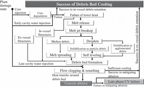
In , a chain of individual phenomena is broken up by the event tree-like approach. In designing an analysis code to realize the authors’ goal, phenomena to be implemented as numerical models can be classified into the following six phenomenological groups:
Molten jet breakup, droplet agglomeration, and debris bed formation
Melt spread on a cavity floor submerged under water
Water-vapor two-phase thermal hydraulics in a heterogeneous debris bed piled on a cavity floor
Debris bed morphological changes (Self-leveling of particle layers)
Debris bed morphological changes (Penetration of molten metals and/or molten oxides into solidified oxide particle beds, remelting and solidification)
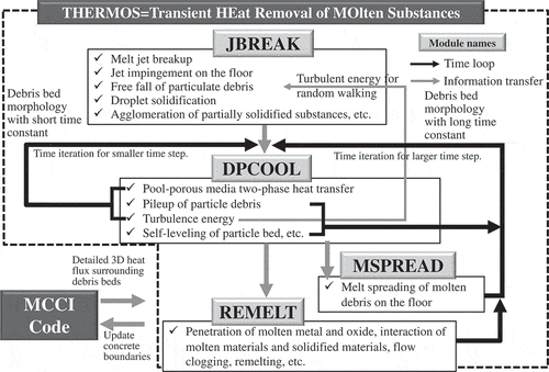
THERMOS (Transient HEat Removal of MOlten Substances) was designed to answer this subject by dealing with these five groups. As summarized in , a basic philosophy is a modularized system where four modules, JBREAK, DPCOOL, MSPREAD, and REMELT, can be applied as standalone codes for a specific range of phenomena groups or they can be coupled according to a range of accident scenarios. A more comprehensive description of the code system can be found in Refs [Citation7].
3. Development of validation matrix
As listed in , the five target groups introduced in Chapter 2 are further subdivided into elemental phenomena. In this table, these elemental phenomena are linked with available test data found from open literatures from the viewpoint of suitability for validation of THERMOS modules, i.e. test conditions (jet diameter, melt superheat, dry or wet floor/multidimensionality, etc.), data items and spatial and temporal data resolutions. A part of validations based on the existing tests had been performed and published or are planned as indicated as ‘C’ and ‘P’, respectively, in . Three new tests, DEFOR-A, PULiMS, and REMCOD have been launched for those phenomena for them it was judged enhancement of the database is desirable. In the following sections, the existing test data for the relevant phenomenon groups were reviewed within the scope of interests in the code development.
Table 1. Important phenomena relevant to the formation and cooling of debris beds, test data and validation plan of THERMOS.
3.1 Molten jet breakup and droplet agglomeration
When partially solidified droplets reaching a floor or a debris bed are closely distributed, they bond together to form agglomerates which are difficult to be cooled due to their low open porosity. If a melt jet with the large diameter enters into a shallow pool, a part of the molten jet reaches a floor and may entrap neighboring solidified droplets, which promotes agglomeration. While there are sufficient test data for the jet breakup length and droplet size distribution, only limited test data are available for the fraction of agglomerated debris.
Moriyama et al. [Citation14] conducted a series of JAEA-ALPHA jet breakup tests using ZrO2-Al2O3 and stainless steel (hereinafter referred to as SS) as simulant materials. They developed the database that consists of their own data and the existing corium test data such as FARO [Citation15], CCM [Citation16], and COTELS [Citation17] and derived correlations of the generation rate and size distribution of droplets. In recent premixing droplet size data obtained in the OECD/CSNI/SERENA2 project, it was confirmed that the TROI-VISU data [Citation18] are located at the lower boundary and the KROTOS-3 data [Citation19] are located in the center of Moriyama’s database [Citation20].
Contrary to the droplet size distribution, the droplet agglomeration had been reported in limited corium tests [Citation15,Citation16] and simulant tests [Citation21,Citation22]. In the pre-mixing cases using corium materials, L14 and L28, conducted in FARO, the data of 16% and 44% were reported as the mass fraction of droplet agglomeration found at the bottom of a test section with jet diameters of 92 and 44 mm and pool depths of 2.05 and 1.44 m, respectively [Citation15]. The first systematic test focusing on the droplet agglomeration was carried out by Kudinov et al. using the DEFOR-A facility with Bi2O3-WO3 as a simulant material [Citation23]. They conducted nine cases, from A1 to A9, in a jet diameter range of 10 to 25 mm and a pool depth range of 1.42 to 1.52 m. Particles and agglomerated debris were captured by four net catchers that were vertically arranged at a 0.3 m pitch. Each catcher roughly covered one-quarter of the planar cross section. The droplet agglomeration was observed at a high mass fraction range of 25 – 90% at the top catcher placed between 0.5 and 0.6 m below a water surface where the jet breakup was estimated to be completed [Citation23]. In the present research, we extended the existing agglomeration database of DEFOR-A into a wider parameter range for developing and validating the droplet agglomeration model to be implemented in JBREAK. In particular, an attention will be paid to mechanisms through which the melt superheat gives significant impacts on the high agglomeration rate observed in a shallow range as will be discussed in Section 4.1. As the corium test, FARO is regarded as a validation candidate.
3.2 Underwater melt spread on a cavity floor
Several preceding cases of melt spread tests on a dry floor had been conducted, such as CORINE [Citation24], KATS [Citation25] and ECOKATS [Citation26] using simulant materials, VULCANO [Citation27] and FARO [Citation28] using corium. While one-dimensional spreading behaviors were mainly focused on long rectangular channels [Citation25] or small angle sector sections [Citation24,Citation27,Citation28], local flow stops and branches into rivulet like tributaries were also observed at leading edges of melt in some of these tests [Citation25]. Mechanisms of these anisotropic spreading behaviors differ between a low-viscosity flow with a small melt thickness and a medium or high-viscosity flow with a large melt thickness (i.e. the high driving head). As a latter example, conspicuous anisotropic spreading could be observed in the ECOKATS-1 test soon after melt flew out of the inclined channel and entered into the 4 m 3 m rectangular floor [Citation26]. From the VTR footages, it can be interpreted that fragments of thin solidified crusts floating on an upper melt surface were carried forward by an underlying melt flow. They built up at some parts of leading edges and formed weirs that blocked melt spreading locally. Then, tributaries would be caused by several mechanisms [Citation29].
MSPREAD had already been validated based on KATS-12 and VULCANO-VE-U7 for one-dimensional spreading behaviors [Citation30]. The model for local stop and reflow was developed and was validated based on the ECOKATS-1 test [Citation29]. The two-phase friction model considering the influences of the concrete gas bubbling was implemented according to the works done by Veteau et al. based on the CORINE test [Citation31].
Compared to dry floor tests, there are a limited number of wet floor tests using high-temperature simulants or corium. The heat removal is more efficient but is complicated at an upper melt surface that is in contact with pool water. While the spreading distance decreases, which is disadvantageous in terms of the heat transfer area, there are large uncertainties in the heat removal process on an upper surface that experiences the boiling transition. When local quenches occur at some locations, crusts grow more non-uniformly. In addition, the violent boiling and melt eruption would promote surface unevenness, which will enhance the heat removal [Citation10–Citation13].
Prior to this research, the FARO corium test was conducted on a substrate covered with a shallow water layer. It was reported that no water effect was observed [Citation28]. In KATS-4 and KATS-10, a molten mixture of Al2O3 and Iron was dropped into a shallow pool. While the small-scale steam explosions were observed, it was reported that the spreading distance was shorter than those observed in dry floor tests [Citation32]. Although low melting point alloys were used, the jet breakup and formation of a porous layer during initial melt-water interactions were observed in the S3E test conducted by KTH [Citation33]. The PULiMS test conducted by KTH was the only preceding systematic spreading test. This test was started by releasing simulant melt from the nozzle located just above a pool surface in order to include the molten jet breakup, impingement on a floor and other effects occurring in a short distance in a pool. In four cases (PULiMS-E1, E3 – E5), molten simulants of Bi2O3-WO3 and ZrO2-WO3 were dropped into a 0.2 m depth water pool. Test conditions included the water subcooling of 21 to 28 K, jet free fall height of 400 mm, jet diameter of 20 mm and melt superheat of 70 to 300 K. MCI occurred in two out of the four cases [Citation34]. In this research, the term, MCI, is defined as a group of violent interactions that occur when high-temperature molten materials are poured into a water pool, i.e. pre-mixing, various scales of boiling that result in pressure spikes, energetic steam explosion., etc. In the case where the material is corium, the term FCI is used. In the present research, the PULiMS database has been extended for validating MSPREAD on underwater anisotropic spreading with a sufficient level of the driving head under test conditions leading to lower probabilities of MCI.
3.3 Water-vapor two-phase flow heat transfer in a heterogeneous debris bed
Isothermal tests were conducted by Tutu et al. [Citation35] and Chu et al. [Citation36] using non-heating particle layers with air injection. Based on these data, the fluid-particle and interfacial friction forces under the water-vapor two-phase flow were modeled. In these models, the relative permeability and passability were expressed as rational functions of the water fraction that was regarded as the saturation of the pore volume. Influences of the two-phase flow interface structure (bubbly, slug and annular) were taken into account via the two-dimensional map where the particle diameter and void fraction were regarded as independent variables [Citation37,Citation38].
As directly heated particle layer tests, a series of the COOLOCE test was conducted using a mixture of oxide spheres (ZrO2 + SiO2) and irregularly shaped alumina gravel packed in several three-dimensional geometries, a cylinder, cone and truncated cone () at the porosity about 0.35 to 0.4. Temperature distributions of layers preceding dryout were measured [Citation39]. In the POMECO test, a tall prism test section (
) was employed and was filled with different sizes of sand particles with homogenous and stratified porosity distributions. The dryout heat flux was measured with or without a downcomer [Citation40].
As induction-heated particle layer tests, the SILFIDE test employed a flat rectangular section () filled with SS spheres of diameters of 2 to 7 mm at the porosity of about 0.4. Temperature distributions in a particle layer were measured until the occurrence of dryout [Citation41]. The IKE (Institute for Nuclear Technology and Energy Systems) has conducted a long series of the DEBRIS test. In this test series, a cylindrical test section (
) was filled with steel spheres, mixtures of steel spheres and irregularly shaped alumina particles and arbitrarily shaped materials such as SS screws. Here, several boundary conditions postulated in a degraded core were simulated, such as top-flooding, bottom-flooding and a central downcomer tube with and without wall leak holes [Citation42–Citation44]. As a more recent test, the PEARL test employed a large cylindrical test section (
) that was filled with 4 mm steel spheres and the quench front progression during reflooding was observed under practically homogeneous heating conditions [Citation45].
In validating DPCOOL, models of fluid-particle and interfacial frictions, which are key elements in the momentum conservation equation, have been validated based on results of Chu’s air injection test and three IKE’s DEBRIS cases, top flooding, bottom flooding and center downcomer [Citation7,Citation8]. Prediction of dryout caused by CCFL (Counter-current flow limitation) was demonstrated based on the COOLOCE-13 test [Citation7]. Since a debris bed is composed of many components, such as particulate debris and heat structures, further tests are necessary to develop the closure equations of heat transfer coefficients between these components, i.e. a combined heat transfer of particle-structure contact and fluid convection at the interface of particle debris and heat structures [Citation46] as summarized in .
3.4 Morphological change in debris bed (self-leveling of particle layers)
The downward impact force due to the particle sedimentation on a floor is important as the initial driving force for the self-leveling. However, in order to facilitate understanding of the phenomenon, the past tests on the self-leveling had been conducted from the stationary particle layers. The self-leveling of particle layers is induced by the balance of gravity, buoyancy, inter-particle friction and fluid-particle friction. This subject was investigated by Hesson et al. [Citation47] and Gabor et al. [Citation48] in the 1970s. In recent years, tests aimed for application to the fast breeder reactors were carried out by Cheng et al. [Citation49] and Morita et al. [Citation50]. They employed a cylindrical test section filled with particle layers submerged under water. Nitrogen was injected from below the test section. Al2O3 (spherical, irregular), ZrO2 (spherical), Zn (irregular), SS (spherical, irregular) and copper (irregular) were used as particle materials. The particle diameters ranged from 1 to 6 mm. They reported that the leveling of irregularly shaped particles progressed slower than that of spherical particles of the same material, which differed from observations reported by Gabor et al. [Citation48]. Based on these more recent observations, Morita et al. proposed a model including the time constant of the leveling progression in a range of sphericity = [0.39:1.0] [Citation50]. In the field of light water reactors, Basso et al. performed the PDS-C test with an upright rectangular section. Spherical SS particles (diameters = 1.5, 3.0, 6.0 mm), cylindrical SS particles (equivalent diameter = 3.4, 4.3 mm) and mixtures of spherical and cylindrical particles were submerged under water. The sphericity ranged from 0.8 to 1.0 and boiling was simulated by injecting air from below the test section [Citation51–Citation53].
In this research, the multi-dimensional spreading model that was developed based on the Basso’s one-dimensional theory was implemented in DPCOOL and was validated based on the PDS-C test [Citation7]. It is important to note that Basso’s test does not sufficiently validate how parameters, such as irregular surface geometries, influence actual leveling progressions of particle layers. Hence, further validations based on Cheng and Morita’s tests are planned. Regarding influences of the particle sedimentation, Sheikh et al. conducted systematic tests employing particle materials, particle diameters and discharge nozzle diameters as parameters and they proposed the empirical model for predicting the initial bed shape based on the dimensionless analysis [Citation54]. Their test data and models are useful for developing the interface model connecting the molten jet breakup with the self-leveling.
3.5 Penetration of molten metals and/or molten oxides into solidified oxide particle beds
REMELT deals with cavity debris beds in which the fuel lattice is largely collapsed and most of the core components are molten or granulated. This code focuses on molten materials of metal origin and how they penetrate into high-temperature layers built by refractory ceramic particles, which is accompanied by material interactions such as phase changes and eutectic reactions. From this point of view, Buck reviewed the existing test database useful for validating the late-phase core degradation models [Citation55].
As separate effect tests, the fluid dynamics of penetration into a particle layer should be validated under conditions where contributions of the gravity head, fluid-particle friction, capillary force and phase changes caused by the temperature gradient are not obscured by influences of material interactions. Considering large density ratios between molten metal and other fluids (coolant and gaseous materials), it can be assumed that a penetration flow field is dominated by the momentum of molten metals. As a part of pioneering works by Reed, the momentum equation was developed where the relative permeability and passability were expressed as rational functions of the effective fluid saturation in the porous media and the capillary pressure was expressed as a function of the contact angle, surface tension, porosity, permeability and effective saturation via the Leverette S–shape curve. The formulation of the effective saturation includes the residual saturation under which the melt is unconnected in pore volumes due to the strong capillary force. He also conducted several non-condensable gas-liquid two-phase flow tests using small diameters particles made of glass and iron while static characteristics such as the channeling length and the steep axial gradient of saturation were mainly focused [Citation56].
In the OECD-MASCA Phase 2 project, several parametric studies on the penetration of molten metals in corium particle layers were carried out. Here, it was found that the penetration distance depends not only on the particle size but also on the wettability, which in turn is strongly dependent on material interactions such as the oxidation degree and formation of high melting point metal carbides produced by reactions with carbon contained in iron and a heater [Citation57]. In the present research, it was judged to obtain the visualized penetration data using the newly installed REMCOD facilities under conditions where the complexity of penetration behaviors is not enhanced by using inert combinations of low melting point fusible metals and particle materials [Citation9].
As integrated effect tests including material interactions, PHEBUS FPT4 focused on the late-phase core degradation, release of low-volatility radioactive materials and formation of a molten pool. This test employed a debris bed of enriched UO2 + ZrO2 particles in the upper 2/3 and depleted UO2 particles in the lower 1/3 [Citation58]. Two MP (Melt Progression) tests, MP-1 and MP-2, were carried out under fission heating driven by ACRR (Annular Core Research Reactor) to investigate the formation of ceramic fuel melt and its relocation through intact fuel bundles postulated in the late phase of core degradation. The test section was composed of a rubblized bed consisting of UO2 and ZrO2 fragments overlying a mockup lattice composed of 32 intact fuel rods, a metallic blockage composed of Zircaloy, PWR control materials, SS and some dissolved UO2. In the MP-2 test where temperature recorded higher, the fuel melt progressed into the fuel stub array about halfway through the metallic crust. Based on post examinations, it was inferred that metal with a low melting point could penetrate through high melting point solid oxide [Citation59]. These typical fission heating tests employed specific core configurations such as UO2 mixed with fully oxidized zirconium and PWR control materials (Ag-In-Cd). In ongoing material researches on fuel debris for decommissioning Fukushima Daiichi NPS, the presence of high hardness and refractory phases (e.g. borides) is recognized in addition to the immiscible oxide and metal phases [Citation60]. In order to estimate the effects of this third phase, it is necessary to refine models implemented in REMELT based on the REMCOD test database.
Figure 2. A structure of THERMOS composed of four modules.
4. Present status of tests
According to discussions in Sections 3.1, 3.2 and 3.5, the DEFOR-A and PULiMS tests were upgraded for extending the databases for droplet agglomeration and underwater melt spreading. The REMCOD-1, 2 and 3 tests have been newly started for obtaining the systematic and parametric database for penetration behaviors of molten metals in a solid particle layer. shows a schematic view of three test facilities. shows the progress of each test, code development and V&V (verification & validation). In the following chapters, we summarize the status of each test and introduce representative data trends [Citation9–Citation13].
Figure 3. Schematic view of three facilities in the KTH test series.
DEFORA [Citation9]
PULiMS [Citation9]
REMCOD-1 and 2 [Citation11–Citation13]
![Figure 3. Schematic view of three facilities in the KTH test series. DEFORA [Citation9]PULiMS [Citation9]REMCOD-1 and 2 [Citation11–Citation13]](/cms/asset/c6def120-69e0-43d6-8e9a-7ea111ef3975/tnst_a_1691078_f0003_oc.jpg)
Table 2. Schedule of experimental and analytical investigation of the formation and cooling phenomena of high-temperature debris bed [Citation9–Citation13].
4.1 DEFOR-A test
The DEFOR-A test was carried out in an approximately 2 m tall rectangular tank with a cross section 0.5 m × 0.5 m as displayed in ). Side windows are made of Plexiglas for direct view observation. A binary oxidic composition, Bi2O3:WO3 = 43:57 (mass %), was charged in a furnace for melt preparation. The composition is eutectic with the estimated melting point of 1143 K according to the phase diagram. The density, viscosity and surface tension of melt are close enough to those of oxidic corium. As is common to ceramic materials, a time constant of the heat conduction is long enough compared to that of the heat transfer. Therefore, solidification starts from surfaces of droplets and gradually propagates inward, which is also expected in corium droplets. The temperature was monitored by thermocouples located at crucible, funnel and other multiple locations in a pool. Jet breakup behaviors were captured from the high-speed video. Four catchers made of SS plates were placed at equal vertical intervals of 300 mm. Each catcher roughly covered one-quarter of the planar test section. In all cases, Catcher-1 was located at the highest elevation where jet breakup was estimated to be complete. A metallic net was attached at the periphery of each catcher to capture droplets and solidified particles. The distribution of particle size was obtained by sieving. The mass fraction of agglomerated debris was measured by removing particle portions from solidified beds collected at the bottom. Geometries (height) of captured particle beds were digitized with the laser scanner as exemplified for A27 in ). The beds’ volume and porosity were evaluated with few percent errors.
Figure 4. Representative data of the DEFOR-A test.
Agglomerated debris data [Citation11–Citation13], [Citation23], [Citation61]
Laser scanning image of captured debris (A27) [Citation13]
![Figure 4. Representative data of the DEFOR-A test. Agglomerated debris data [Citation11–Citation13], [Citation23], [Citation61]Laser scanning image of captured debris (A27) [Citation13]](/cms/asset/a69b04fa-adfe-418c-bcb3-2f8f86dcbeb2/tnst_a_1691078_f0004_c.jpg)
Test parameters are listed in . Case IDs in and are the serial numbers of all cases carried out thus far in KTH using the DEFOR-A and PULiMS setups. Five cases, A23 to A27, were carried out in this research. As exhibited in ), the mass fraction of agglomerated debris sharply decreased as the distance from a pool surface increased. In A7 and A9, which were conducted at the high melt superheat, the agglomeration fraction did not change monotonically with the distance. For these cases, it was reported that only a small portion of melt was captured in Catcher-1 presumably due to inward distortion of the net, which caused many droplets to rebound outside of the catcher. In A27, by changing the catcher design, the agglomeration fraction exhibited a trend similar to those of other cases, but still maintained at a high level in a wider range of the distance, which can be attributed to the high melt superheat. In A25, with the low melt superheat and larger jet diameter of 34 mm, the agglomeration fraction did not change monotonically with distance and remained low as a whole. A22_S1, conducted under the auspice of SAFEST (Severe Accident Facilities for European Safety Targets), was run at the melt superheat equivalent to that of A25, but with a smaller jet diameter 24 mm. In this case, a monotonically decreasing trend was observed [Citation61].
Table 3. Test matrix of DEFOR-A [Citation11–Citation13].
Table 4. Test matrix of PULiMS [Citation10–Citation13].
Systematic reproducibility tests were not planned in this study. Significant differences can be observed between the results of different cases conducted under similar conditions. While the impression that the tests are not fully reproducible may be given, these results can reflect a stochastic nature of melt interactions with water. Factors contributing to experimental uncertainties include not only usual measurement errors, e.g. of melt temperature and flow rate, but also technical difficulties to set and keep specific experimental conditions influencing jet fragmentation and melt quenching, such as melt composition and jet dynamics, particle catcher position and geometry evolution during the test, complex hydrodynamics in the water pool during melt pour, etc. It is possible to conclude that the droplet agglomeration is strongly affected by some of these factors. Principal factors/effects, which are not reproduced/studied in DEFOR tests, but can have a strong influence on agglomeration, are (i) decay heat in the melt (ii) oxidation heat at the melt interface with water (steam), and (iii) effect of metal melt. The listed circumstances create strong perspectives for DEFOR experimental research continuation.
Based on A1 to A9, Kudinov et al. noted that agglomeration occurs when low solidification droplets (for example, less than 10% of outer surfaces are solidified) bond together, and, as the first-order approximation, proposed a surrogate model where the agglomerated mass, , is assumed to be proportional to the total mass of liquid droplets,
, at each catcher level which can be estimated by simulations. In an attempt to apply this theory to high melt superheat cases, including A7, A9, and A27, we need to accept significant uncertainties in the proportional relation with respect to
[Citation23]. From closer observations of the VTR footage, it is likely that large molten fragments, which were stripped from molten jet tips were captured by the catchers at the higher elevation and they could entrap neighboring solidified droplets, which promotes droplet agglomeration. These detailed aspects will be taken into account in developing the agglomeration model in JBREAK.
4.2 PULiMS test
The PULiMS facility is a shallow depth container with four 20 mm thick acrylic side windows and an SS bottom floor as illustrated in ). The typical water pool depth is 0.2 m. An eutectic mixture, Bi2O3:WO3 = 43:57 (mass %), was charged in the furnace for melt preparation and released into a container from a nozzle positioned close to a pool surface. As spreading geometries, the omnidirectional system, 360 ° and the two-sector systems, 180 ° and 90 °, partitioned by quartz glass plates were employed. In the sector cases, quartz glass plates were slightly biased from the jet centerline to allow visual observation of jet arrival to a floor and subsequent melt spreading cut by the plates. Four force sensors were installed at the bottom of legs supporting a container to monitor the mass settled on a floor and the dynamic load caused by MCI.
The parameters, including the final melt compositions prior to delivery into the water pool determined by the SEM/EDX (Energy Dispersive X-ray) analysis for E16-E18 are listed in . The final melt compositions of other cases are planned to be determined in Phase-6. While the estimated melt superheat based on the phase diagram was maintained within 15–92 K to suppress MCI, E15 was performed at the relatively high melt superheat of 150 K. Single and bundled triple thermocouples were installed radially with regard to the jet center on a SS floor. Single TCs monitored the melt arrival near a floor surface while bundled triple TCs monitored local changes of the melt thickness at three elevations. The end-state three-dimensional geometry of solidified beds was digitized via the laser scanning. The debris bed volume and average porosity were then estimated within a few percent error.
So far, 12 cases, from E7 to E18, had been carried out, which has significantly extended the underwater melt spreading database. Histories of spreading front progression measured by the video analysis are plotted in ). For E10, the end-state spreading shape captured by the camera and laser scanning is presented in ). During the early spreading period, the film boiling persisted and the melt surface looked smooth. Visual observation became difficult in the latter spreading period due to the generation of dense black clouds masking a wide range of a pool. As shown in ), large unevenness grew during the growth of an upper crust surface. Post examinations of the debris cross section, as illustrated in ), indicated that unevenness was produced by the growth of internal cavities and melt eruptions that were likely to be driven by violent boiling of water being entrapped during jet impinging or recirculating inside debris in the process of solidification. This observation of the upper surface unevenness needs to be taken into account when modeling the heat removal during spreading.
Figure 5. Representative data of the PULiMS test.
Comparison of spreading front positions measured by video analysis [Citation12,Citation13]
End state of E10 [Citation12]
Post examination of E10 [Citation12]
Post examination of E13 [Citation12]
![Figure 5. Representative data of the PULiMS test. Comparison of spreading front positions measured by video analysis [Citation12,Citation13]End state of E10 [Citation12]Post examination of E10 [Citation12]Post examination of E13 [Citation12]](/cms/asset/755b5ac1-fa90-4dab-8475-a5eaf51dc159/tnst_a_1691078_f0005_c.jpg)
In some cases such as E7, E13, E14, E15 and E16, presence of metallic Bismuth (yellow-white) at the bottom crust could be seen as shown in ). For E16, a melt sample was taken from the crucible prior to pouring. The solidified sample was sent for the SEM/EDX analysis. Along with metallic Bismuth formation, it was inferred that the melt does not belong to the WO3-Bi2O3 system but to the WO3-Bi2O3-Bi system possibly due to chemical interactions between simulant materials and crucible materials. By assuming solubility of Bi in Bi2O3, an uncertainty range of oxidic composition and the liquidus was estimated for E16, E17 and E18 [Citation13].
As depicted in , MCIs were observed in three cases for which the melt superheat was relatively high. In E7, the maximum load, 109 kN, and impulse, 0.605 kN-sec, were recorded after a significant amount of melt arrived and spread on a floor. The melt superheat was somewhat high, 92.2 K, and the melt mass contributing to MCI was large, which led to the relatively energetic stratified MCI. In E15, a part of melt, 7.4 kg, dropped into a pool directly from a furnace without passing through a funnel, and it is likely that dispersed melt fragments collided against a water surface and small-scale MCIs occurred. The recorded maximum load was 7.4 kN with negligible impulse. In E17, the large heat loss inside a funnel caused solidified melt to clog a release path and as a result, melt dripped off slowly to deposit on a floor. Microscale MCIs were frequently observed. The maximum load was as small as 0.87 kN, while the impulse was also negligible.
When paying attention to those mechanisms that have not been sufficiently elucidated in the past such as tributary branching and top surface crust unevenness, it is desirable to develop models describing their impacts on heat removal during spreading and to quantify uncertainties through simulation of PULiMS cases. As for the final composition of solidified simulants, further analyses of the debris of already conducted cases are planned to correct the liquidus-solidus gap and uncertainties can be reduced at this point. It was also found that interactions between melt materials and a crucible made of SiC/C generated black clouds. In E17 and E18, a dual crucible was introduced where a smaller Al2O3 crucible was nested in a larger SiC/C crucible and the gap was filled with ZrO2. This new design dramatically suppressed the generation of black clouds as shown in ). This improvement in test procedures will contribute to the understanding of the phenomena described above and model development.
Figure 6. Melt-coolant interactions observed in PULiMS.
E7 [Citation10]
E15 [Citation12]
E17 [Citation13]
![Figure 6. Melt-coolant interactions observed in PULiMS. E7 [Citation10]E15 [Citation12]E17 [Citation13]](/cms/asset/996fc298-1a83-44b3-a744-675ee25390d1/tnst_a_1691078_f0006_c.jpg)
4.3 REMCOD test
Major validation targets in REMCOD are models included in the momentum equation of REMELT. In particular, those models for the effective and residual saturations [Citation56] that govern the fluid-particle friction and the capillary pressure are important. It is essential to know the contact angle data for different combinations of molten metals and particle materials as reported in the test reports [Citation9–Citation13]. Single component and eutectic composition metallic materials are used so that the phase change occurs in a narrow temperature range.
These tests were started from the exploratory tests aiming to establish basic test procedures and instrumentation techniques to be applied to REMCOD-1, 2 and 3. In REMCOD-1 and 2, a thin rectangular test section was made of an aluminum frame fitted with quartz glass windows on the front and back sides. As depicted in ), this section was divided into two or four compartments via SS separators. Each compartment was filled with layers of spherical or cylindrical particles made of alumina, SS, glass, zirconium silicate and copper of various sizes. Tin (melting point 505.2 K) was used in the exploratory test and Tin-Bismuth eutectic alloy (atomic ratio Sn:Bi = 61:39, melting point 412.2 K) [Citation62] was used for REMCOD-1 and 2. In each setup, a horizontally movable funnel was placed above each compartment to pour the melt from the top of the particle layers. The melt pouring rate was monitored by three force sensors installed at the bottom of the frame. Thermocouples were installed at the funnel, upper, middle, and lower parts of each particle layer.
In the exploratory tests (E01 to E07), particle layers were maintained at room temperature without heating. In E08 and later cases, a fixed heater plate was attached to the backside while a removable heater plate was attached to the front side. Penetration flow was visually observed at the timing when the front heater plate was removed. The REMCOD-3 facility was designed to resolve some technical issues found in REMCOD-1 and 2 such as difficulties of fixing the temperature profile, inter-compartment leak flow and heat loss due to a large surface area to volume ratio of the test frame. A cylindrical quartz test section was placed in a tubular furnace that accommodates the higher temperature, 1473 K max, and reduces the heat loss from sidewalls. A vertical temperature profile is provided by three independent heating zones and a control system that enables us to give both the stationary and transient temperature profiles.
Parameters in the REMCOD exploratory test and REMCOD-1 and 2 test series are listed in . Melt superheat, particle materials, particle shape, porosity and (initial) temperature distributions of particle layers were varied. Al2O3 and SS used in REMCOD-1 have the contact angle with the melt >90 deg., while glass has the contact angle of approximately 90 deg. In these cases, the particle size ranged from 3 to 6 mm and the capillary pressure did not play a major role in the penetration. In REMCOD-2 (E12 and later), influences of capillary pressure were more pronounced by using 1.5 mm diameter particles made of copper which has the higher thermal conductivity and larger wettability.
Table 5. Test matrix of REMCOD-1 and 2 [Citation11–Citation13].
(a) shows the end state of metal penetration in E11 where the four compartments, from C1 to C4, were filled with Al2O3 cylinders (6 mm × 6 mm), SS spheres (3 mm), SS spheres (
1.5 mm) and zirconium silicate particles (
0.8 mm), respectively. (b) exhibits the progression of the melt front location obtained by the video footage. It was also observed that more molten metal accumulated on top of layers as the particle size decreases. Consequently, the gravity head of accumulated metal became dominant; then, as the metal was absorbed into the layers, a constant velocity state was realized due to the balance of the gravity and liquid metal-particle friction [Citation13]. In ), the penetration distance was plotted against the net excess enthalpy of a whole liquid metal and particle layer at the initial state,
, in E08 where Al2O3 cylinders (6 mm × 6 mm) was filled in each column. Here
is the heat needed for the particle layer to heat-up from its initial temperature to the melting point of the metal phase. The term
is the initial sensible heat of the metal phase. It was found that the penetration distance until crust formation showed a clear correlation with the excess enthalpy. ) shows the final state retention of solidified metal per the unit surface area against the porosity for E09 and E11 where the data of four particles materials, Al2O3, SS, glass and zirconium silicate, two-particle shapes, spherical and cylindrical, and a size range from 1 mm to 6 mm are included. Although this is the data of two cases, it was suggested that the final retention of the solidified metal in a particle layer can be correlated by the porosity regardless of materials and particle sizes.
Figure 7. Representative data of the REMCOD test.
End state of E11 [Citation12]
Penetration histories in E11 [Citation12]
Penetration vs bed temperature in E08 [Citation12]
Melt retention vs porosity in E09/E11 [Citation12]
![Figure 7. Representative data of the REMCOD test. End state of E11 [Citation12]Penetration histories in E11 [Citation12]Penetration vs bed temperature in E08 [Citation12]Melt retention vs porosity in E09/E11 [Citation12]](/cms/asset/901c7e81-dc84-4962-b90f-1d1aa59c6d0d/tnst_a_1691078_f0007_c.jpg)
5. Conclusions
Three tests, DEFOR-A, PULiMS, and REMCOD, have been performed within the five completed phases of the project. These tests have been conducted in parallel with modeling and coding of THERMOS that was designed for evaluating the cooling states of underwater debris beds. Technically challenging transient experiments with high temperature melts interacting with water and/or vapor were conducted as a systematic study by varying the influential parameters to supply data for code validations.
These tests have enabled the considerable extension of the knowledge base for model development in this area. The database has been reinforced, particularly, for DEFOR-A and PULiMS, by running confirmatory cases for potential outliers in past tests. In REMCOD, it is expected to provide an important database on the penetration of low melting point metals into solid particle layers without conspicuous influences of material interactions. New effects observed in the tests, such as various scales of MCIs in PULiMS, can be important for the ex-vessel core melt stabilization under the wet cavity strategy. The 6th phase of the project targets debris remelting tests with the new REMCOD-3 facility, as well as additional posttest analyses and qualifications of completed DEFOR-A and PULiMS tests.
Lastly, the planning, performance, data collection and data analyses of the three tests are being published as separate reports for each phase. In conjunction with this paper and these test reports, it is planned that data sharing will be promoted under open academic discussions. It is expected that further data analyses not only by the authors bust also by researchers of relevant fields will deepen phenomenological understanding and model development that will eventually contribute to the safety enhancement of nuclear power plants.
Acknowledgments
The authors would like to thank the former members of the Nuclear Power Safety Division at KTH Dr. D. Grishchenko, Assoc. Prof. P. Kudinov and Dr. A. Karbojian for their valuable contribution to this project.
Disclosure statement
No potential conflict of interest was reported by the authors.
References
- Corradini ML, Kim BJ, Oh MD. Vapor explosions in light water reactors: a review of theory and modeling. Prog Nucl Energy Technol. 1988;22(1):1–117.
- Piluso P, Adorni M, Basu S et al. Status report on ex-vessel steam explosion. OECD/NEA/CSNI; 2018 Mar. (NEA/CSNI/R(2017)15). Available from: https://www.oecd-nea.org/nsd/docs/2017/csni-r2017-15.pdf
- Alsmeyer H. Proc. Second OECD (NEA) CSNI specialist meeting on molten core debris-concrete interactions; 1992 Apr 1–3; Karlsruhe, Germany. NEA/CSNI/R(92)10.
- Farmer M, Basu S, Cranga M, et al. State-of-the-art report on molten corium concrete interaction and ex-vessel molten core coolability. 2017. (NEA/CSNI/R(2016)15). Available from: https://www.oecd-ilibrary.org/nuclear-energy/state-of-the-art-report-on-molten-corium-concrete-interaction-and-ex-vessel-molten-core-coolability_c44872b1-en .
- Sehgal BR, Helle M, Dinh TN et al. Final report for the ‘melt-vessel interactions’ project. Sweden: Royal Institute of Technology: European Union R&TD Program 4th Framework; 1999 Apr.
- Fichot F, Bonnet J-M, Chaumont B. IRSN views and perspectives on in-vessel melt retention strategy for severe accident mitigation. Proceeding EUROSAFE FORUM; 2015 Nov 2–3; Brussels, Belgium.
- Hotta A, Akiba M, Morita A, et al. Research on development of simulation codes for physicochemical phenomena including large uncertainties under severe accident of LWR. 2019 Oct. Japan: Regulatory Standard and Research Department, Secretariat of Nuclear Regulation Authority (S/NRA/R). Available from: https://www.nsr.go.jp/data/000286981.pdf
- Hotta A, Akiba M, Doi Y, et al. Development of debris bed cooling evaluation code, DPCOOL, based on heating porous media submerged in two-phase pool. J Nucl Sci Technol. 2019;56(1):55–69.
- Division of Nuclear Power Safety. Investigation of cooling phenomena of high temperature molten core Phase-I: establishment of experimental plan and experimental facility. Japan: Royal Institute of Technology; 2019 Feb.
- Ditto. Phase-II: melt-coolant interaction experiments on melt spreading under water. Japan: Royal Institute of Technology; 2019 Sep.
- Ditto. Phase-III: commissioning and exploratory test series of REMCOD-1 facility. Second series of experiments on debris bed formation and liquid melt spreading. Japan: Royal Institute of Technology; (to be published)
- Ditto. Phase-IV: remelting of multi-component debris (REMCOD), debris bed formation (DEFOR), pouring and underwater liquid melt spreading (PULiMS). Japan: Royal Institute of Technology; (to be published)
- Ditto. Phase-V: modification of the facilities and third test series of separate effect studies. Japan: Royal Institute of Technology; 2019 Mar.
- Moriyama K, Maruyama Y, Usami T, et al. Coarse break-up of a stream of oxide and steel melt in a water pool (contract research). Japan; JAEA; 2005 Aug; (JAERI-Research 2005-017).
- Magallon D. Huhtiniemi I and Hohmann H. Lessons learnt from FARO/TERMOS corium melt quenching experiments. Nucl Eng Des. 1999;189(1):223–238.
- Spencer B, Wang K, Blomquist C et al. Fragmentation and quench behavior of corium melt stream in water, USA: Argonne National Laboratory; 1994. (NUREG/CR-6133).
- Kato M, Nagasaka H, Vasiliev Y, et al. COTELS project (2): fuel coolant interaction tests under ex-vessel conditions. Proceeding OECD Workshop on ex-vessel debris coolability; 1999 Nov. 15–18; Karlsruhe, Germany. FZKA6475: 293-300.
- Hong S, Kim J, Min B, et al.TROI TS-VISU Test data report. Korea: KAERI; 2010. (OECD/SERENA-2010-TR06 (TS-VISU)).
- Grishchenko D, Piluso P, Fouquart P et al. KROTOS KS-3 Test data report. France: CEA; 2011. (OECD/SERENA-2011-TR07).
- Hotta A, Morita A, Kajimoto M, et al. Simulation of fuel-coolant interaction SERENA2 test based on JASMINE version 3. Trans Atomic Energy Soc Jpn. 2017;16(3):139–152. in Japanese.
- Karbojian A, Ma W, Kudinov P, et al. A scoping study of debris bed formation in the DEFOR test facility. Nucl Eng Des. 2009;239(9):1653–1659.
- Kudinov P, Karbojian A, Ma W, et al. The DEFOR-S experimental study of debris formation with corium simulant materials. Nucl Tech. 2010;170(1):219–230.
- Kudinov P, Karbojian A. Tran CT, et al. Agglomeration and size distribution of debris in DEFOR-A experiments with Bi2O3–WO3 corium simulant melt. Nucl Eng Des. 2013;263:284–295.
- Veteau JM, Wittmaak R. CORINE experiments and theoretical modeling. Proceeding FISA-95, EUR 16896 EN; 1996 271–285; Luxemburg.
- Eppinger B, Fieg G, Massier H et al. Simulationsexperimente zum Ausbreitungsverhalten von Kernschmelzen: KATS-8 bis KATS-17. Germany: Forschungszentrum Karlsruhe GmbH Technik und Umwelt; 2001 März. (FZKA 6589).
- Alsmeyer H, Cron T, Foit JJ et al. Test report of the melt spreading tests ECOKATS-V1 and ECOKATS-1. Germany: Forschungszentrum Karlsruhe GmbH Technik und Umwelt; 2004 Nov. (FZKA 7064 SAM-ECOSTAR-D15).
- Journeau C, Haquet JF, Spindler B, et al. The VULCANO VE-U7 Corium spreading benchmark. Prog Nucl Energy. 2006;48(3):215–234.
- Tromm W, Foit J, Magallon D Dry and wet spreading experiments with prototypic materials at the FARO facility and theoretical analysis. Wiss. Ber. 2000. (FZKA 6475,178-188).
- Hotta A, Akiba M, Morita A. Modeling of anisotropic molten debris spreading and simulation of ECOKATS test. Proceeding AESJ Fall Mtg. 1F10; 2019 Sep 11–13; Toyama, Japan.
- Hotta A, Akiba M, Doi Y. Development of multi-dimensional melt spreading behavior analysis code MSPREAD - Code structure and validation based on simulant test data -. Proc. AESJ Spring Mtg. 3J12; 2018 Mar 26–28; Osaka, Japan.
- Veteau JM, Spindler B, Daum G Modelling of two-phase friction from isothermal spreading experiments with gas fed from the bottom and application to spreading accompanied by solidification. Proc. NURETH-10; 2003 Oct 5–11; Seoul, Korea.
- Fieg G, Huber F, Werle H, et al. Simulation experiments on the spreading behavior of molten core debris. Proc. Natial Heat Transfer Conference; HTC-Vol.9: 121–129, 1996 Aug 3–6; Houston, USA.
- Sehgal BR, Dinh VA, Green JA et al., Experimental investigation of melt spreading in one-dimensional channel. Sweden: RIT/NPS Research Report for European Union; 1997. (EU-CSC-1D1-97).
- Konovalenko A, Karbojian A, Kudinov P Experimental results on pouring and underwater liquid melt spreading and energetic melt-coolant interaction. Proc. NUTHOS9; 2012 Sep 9–13; Kaohsiung, Taiwan. N9P0303.
- Tutu NK, Ginsberg T, Chen JC. Interfacial drag for two-phase flow through high permeability porous beds. J Heat Transfer. 1984;106(4):865–870.
- Chu W, Dhir VK, Marshall J. Study of pressure drop, void fraction and relative permeabilities of two phase flow through porous media. In Heat Transfer Seattle, AIChE Symposium series, vol. 79, series no. 225. American Institute of Chemical Engineers; 1983. p. 224–235. Available from: https://ci.nii.ac.jp/ncid/BA25366662 .
- Tung VX, Dhir VK. A hydrodynamic model for two-phase flow through porous media. Int J Multiph Flow. 1988;14(1):47–65.
- Schmidt W Influence of multidimensionality and interfacial friction on the coolability of fragmented corium [Doctoral Thesis]. Germany: Institut für Kernenergetik und Energiesysteme; 2004; IKE 2-149, ISSN-0173-6892.
- Takasuo E, Taivassalo V, Kinnunen T, et al. Coolability analyses of heap-shaped debris bed. Finland: VTT Technical Research Centre of Finland; 2015 Jan. (NKS-343).
- Konovalikhin MJ, Yang ZL, Amjad M, et al. On dry-out heat flux of particle debris bed with a downcomer. Proceeding ICONE8-8590; 2000 Apr 2–6; Baltimore, USA.
- Atkhen K, Berthoud G. SILFIDE experiment: coolability in a volumetrically heated debris bed. Nucl Eng Des. 2006;236:2126–2134.
- Kulkarni PP, Rashid M, Kulenovic R, et al. Experimental investigation of coolability behaviour of irregularly shaped particulate debris bed. Nucl Eng Des. 2010;240(10):3067–3077.
- Rashid M, Kulenovic R, Laurien E, et al. Experimental results on the coolability of a debris bed with multidimensional cooling effects. Nucl Eng Des. 2011;241(11):4357–4543.
- Rashid M, Kulenovic R, Laurien E. Experimental results on the coolability of a debris bed with down comer configurations. Nucl Eng Des. 2012;249:104–110.
- Chikhi N, Garcin T, Foubert F, et al. First experimental results of large scale debris bed reflood tests in the PEARL facility. Proceeding NURETH-16 2016; N13824, Chicago (USA).
- Fukuoka T, Nomura M, Yamada H. Evaluation of thermal contact resistance at the interface composed of dissimilar materials. Trans JSME (A). 2010;76(763):344–350.
- Hesson JC, Sevy RH, Marciniak TJ Post-accident heat removal in LMFBRs: in-vessel considerations. USA: Argonne National Laboratory; 1971 Sep. (ANL-7859).
- Gabor JD, Sowa ES, Baker L Jr, et al. Studies and experiments on heat removal from fuel debris in sodium. Proc. ANS Fast Reactor Safety Mtg; 1974 Apr 2–4; 823–844; Beverly Hills (USA).
- Cheng S, Yamano H, Suzuki T, et al. Characteristics of self-leveling behavior of debris beds in a series of experiments. Nucl Eng Technol. 2013;45(3):323–334.
- Morita K, Matsumoto T, Nishi S, et al. A new empirical model for self-leveling behavior of cylindrical particle beds. J Nucl Sci Technol. 2016;53(5):713–725.
- Basso S, Konovalenko A and Kudinov P. Effectiveness of the debris bed self-leveling under severe accident conditions. Ann Nucl Energy. 2016;95:75–85.
- Basso S, Konovalenko A and Kudinov P. Empirical closures for particulate debris bed spreading induced by gas-liquid flow. Nucl Eng Des. 2016;297:19–25.
- Basso S, Konovalenko A, Yakush SE and Kudinov P. The effect of self-leveling on debris bed coolability under severe accident conditions. Nucl Eng Des. 2016;305:246–259.
- Sheikh MAR, Son E, Kamiyama M, et al. Sedimentation behavior of mixed solid particles. J Nucl Sci Technol. 2018;55(6):623–633.
- Buck M Modelling of the late phase of core degradation in light water reactors [Doctoral Thesis]. Germany; Institut für Kernenergetik und Energiesysteme; 2007 Nov. IKE 2-172.
- Reed A The effect of channeling on the dryout of heated particulate beds immersed in a liquid pool [Doctoral Thesis]. USA: Massachusetts institute of Technology, Cambridge; 1982 Feb.
- Tsuikov DF, Strizhov VF, Bechta SV, et al. Main results of the MASCA1 and 2 projects. Integrated application Report. 2007. ( NEA/CSNI/R(2007)15).
- Serre F, Crestia JC, Bieder U et al. Phebus FPT4: test description and pretest calculations. Proceeding SARJ-97: 274-278; 1998 Oct. 6–8; Yokohama Japan.
- Gasser RD, Gauntt RO, Bourcier SC et al. Late-phase melt progression experiment: MP-2. Results and analysis. USA: Sandia National Laboratory; 1997 May. ( NUREG/CR-6167).
- Journeau C, Roulet D, Porcheron E, et al. Fukushima Daiichi fuel debris simulant materials for the development of cutting and collection technologies. J Nucl Sci Technol. 2018;55(9):985–995.
- Albrecht G, Miassoedov A, Bechta S, et al., DEFOR-ROD1 Experiment: quick-look Report. Severe Accident Facilities for European Safety Targets (SAFEST) EU Project, 2016 Jul ( SAFEST-DRI-D3.2.3).
- Bi-Sn OH. (Bismuth-Tin). J Phase Equilib Diffus. 2010;31(2):205.